Downloaded 72 times


![Composite reduction
53
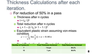
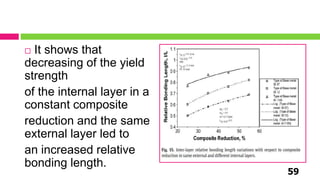
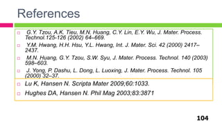
Relative bond length and average
peel strength increases with increase
in composite reduction.
Increase in total composite
reduction moves the created inter-
layer bonding point towards the roll
entrance . This shift can be
interpreted in terms of the critical
deformation required for a cold bond
establishment.
Therefore, it can be stated that the
creation of inter-layer bonding point
originates from existence of the
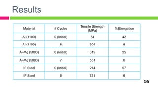
critical strain [39]](https://image.slidesharecdn.com/arbfullppt3rdedit-180521071517/85/Introduction-to-Accumulative-Roll-Bonding-53-320.jpg)
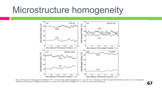


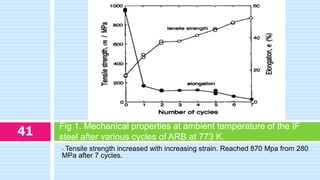
The document provides an in-depth exploration of the accumulative roll bonding (ARB) process for creating ultra-fine grain structures in aluminum and steel, highlighting its advantages over traditional methods. It details experiments conducted to assess grain refinement, tensile strength, and the effects of process parameters, with significant findings such as increased strength and improved ductility in UFG materials. The overall conclusions emphasize the industrial applicability of ARB in various sectors, including construction and aerospace, due to its enhanced mechanical properties.


