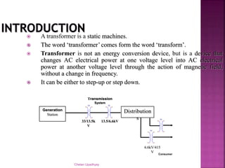
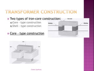
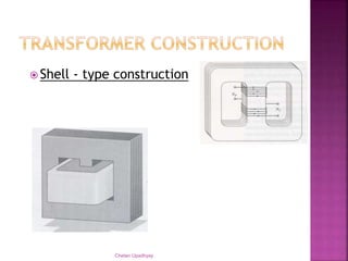
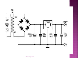
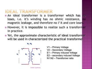
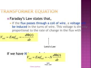
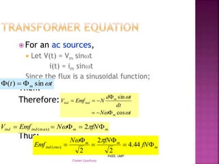
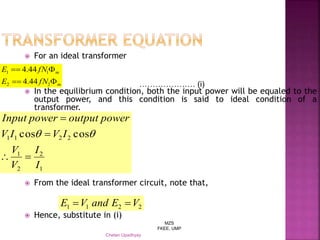
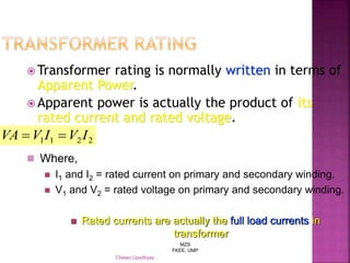
STEPDOWN TRANSFORMER FOR RUNNING A DC MOTOR
SUBMITTED TO-
 HOD . Ravindara meena
SUBMITTED BY-
NAGMANI CHAUHAN(K13075)
NEHA NAGAR(K122366)
Chetan Upadhyay
Chetan Upadhyay
 A transformer is a static machines.
 The word ‘transformer’ comes form the word ‘transform’.
 Transformer is not an energy conversion device, but is a device that
changes AC electrical power at one voltage level into AC electrical
power at another voltage level through the action of magnetic field,
without a change in frequency.
 It can be either to step-up or step down.
Generation
Station
TX1 TX1
Distribution
s TX1
TX1
Transmission
System
33/13.5k
V
13.5/6.6kV
6.6kV/415
V
Consumer
 Two types of iron-core construction:
a) Core - type construction
b) Shell - type construction
 Core - type construction
Chetan Upadhyay
 Shell - type construction
Chetan Upadhyay
Chetan Upadhyay
 An ideal transformer is a transformer which has no
loses, i.e. it’s winding has no ohmic resistance, no
magnetic leakage, and therefore no I2 R and core loses.
 However, it is impossible to realize such a transformer
in practice.
 Yet, the approximate characteristic of ideal transformer
will be used in characterized the practical transformer.
Chetan Upadhyay
V1 V2
N1 : N2
E1 E2
I1 I2
V1 – Primary Voltage
V2 – Secondary Voltage
E1 – Primary induced Voltage
E2 – secondary induced Voltage
N1:N2 – Transformer ratio
MZS
FKEE, UMP
Chetan Upadhyay
 Faraday’s Law states that,
 If the flux passes through a coil of wire, a voltage will
be induced in the turns of wire. This voltage is directly
proportional to the rate of change in the flux with
respect of time.
If we have N turns of wire,
dt
td
EmfV indind
)(

dt
td
NEmfV indind
)(

Lenz’s Law
MZS
FKEE, UMP
Chetan Upadhyay
 For an ac sources,
 Let V(t) = Vm sint
i(t) = im sint
Since the flux is a sinusoidal function;
Then:
Therefore:
Thus:
tt m sin)( 
mmindind fNNEmfV   2(max)
tN
dt
td
NEmfV
m
m
indind


cos
sin



m
mm
rmsind fN
fNN
Emf 



 44.4
2
2
2
)(

MZS
FKEE, UMP
Chetan Upadhyay
 For an ideal transformer
 In the equilibrium condition, both the input power will be equaled to the
output power, and this condition is said to ideal condition of a
transformer.
 From the ideal transformer circuit, note that,
 Hence, substitute in (i)
m
m
fNE
fNE


22
11
44.4
44.4
1
2
2
1
2211 coscos
I
I
V
V
IVIV
poweroutputpowerInput




………………… (i)
2211 VEandVE 
MZS
FKEE, UMP
Chetan Upadhyay
 Transformer rating is normally written in terms of
Apparent Power.
 Apparent power is actually the product of its
rated current and rated voltage.
2211 IVIVVA 
 Where,
 I1 and I2 = rated current on primary and secondary winding.
 V1 and V2 = rated voltage on primary and secondary winding.
 Rated currents are actually the full load currents in
transformer
Chetan Upadhyay
Chetan Upadhyay

Stepdown Transformer By Nagmani

  • 1.
    STEPDOWN TRANSFORMER FORRUNNING A DC MOTOR SUBMITTED TO-  HOD . Ravindara meena SUBMITTED BY- NAGMANI CHAUHAN(K13075) NEHA NAGAR(K122366)
  • 2.
  • 3.
    Chetan Upadhyay  Atransformer is a static machines.  The word ‘transformer’ comes form the word ‘transform’.  Transformer is not an energy conversion device, but is a device that changes AC electrical power at one voltage level into AC electrical power at another voltage level through the action of magnetic field, without a change in frequency.  It can be either to step-up or step down. Generation Station TX1 TX1 Distribution s TX1 TX1 Transmission System 33/13.5k V 13.5/6.6kV 6.6kV/415 V Consumer
  • 4.
     Two typesof iron-core construction: a) Core - type construction b) Shell - type construction  Core - type construction Chetan Upadhyay
  • 5.
     Shell -type construction Chetan Upadhyay
  • 6.
  • 7.
     An idealtransformer is a transformer which has no loses, i.e. it’s winding has no ohmic resistance, no magnetic leakage, and therefore no I2 R and core loses.  However, it is impossible to realize such a transformer in practice.  Yet, the approximate characteristic of ideal transformer will be used in characterized the practical transformer. Chetan Upadhyay V1 V2 N1 : N2 E1 E2 I1 I2 V1 – Primary Voltage V2 – Secondary Voltage E1 – Primary induced Voltage E2 – secondary induced Voltage N1:N2 – Transformer ratio
  • 8.
    MZS FKEE, UMP Chetan Upadhyay Faraday’s Law states that,  If the flux passes through a coil of wire, a voltage will be induced in the turns of wire. This voltage is directly proportional to the rate of change in the flux with respect of time. If we have N turns of wire, dt td EmfV indind )(  dt td NEmfV indind )(  Lenz’s Law
  • 9.
    MZS FKEE, UMP Chetan Upadhyay For an ac sources,  Let V(t) = Vm sint i(t) = im sint Since the flux is a sinusoidal function; Then: Therefore: Thus: tt m sin)(  mmindind fNNEmfV   2(max) tN dt td NEmfV m m indind   cos sin    m mm rmsind fN fNN Emf      44.4 2 2 2 )( 
  • 10.
    MZS FKEE, UMP Chetan Upadhyay For an ideal transformer  In the equilibrium condition, both the input power will be equaled to the output power, and this condition is said to ideal condition of a transformer.  From the ideal transformer circuit, note that,  Hence, substitute in (i) m m fNE fNE   22 11 44.4 44.4 1 2 2 1 2211 coscos I I V V IVIV poweroutputpowerInput     ………………… (i) 2211 VEandVE 
  • 11.
    MZS FKEE, UMP Chetan Upadhyay Transformer rating is normally written in terms of Apparent Power.  Apparent power is actually the product of its rated current and rated voltage. 2211 IVIVVA   Where,  I1 and I2 = rated current on primary and secondary winding.  V1 and V2 = rated voltage on primary and secondary winding.  Rated currents are actually the full load currents in transformer
  • 12.
  • 13.

Editor's Notes