Download to read offline
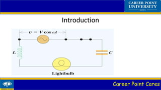
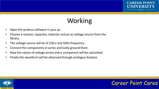
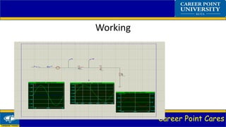


This document summarizes a simulation of an RLC circuit using Proteus software. It introduces RLC circuits and describes how to build one in Proteus using a resistor, capacitor, inductor, and AC voltage source connected in series. The voltages across each component are then calculated and waveforms observed through analog analysis. RLC circuits are commonly used in AM/FM radios, oscillators, and pulse discharge circuits.