This document discusses initial conditions in circuits when switches change position. It states that:
1) At t=0-, just before a switch changes, indicates the circuit conditions.
2) At t=0, the instant the switch changes position.
3) At t=0+, just after the switch changes, indicates the new circuit conditions.
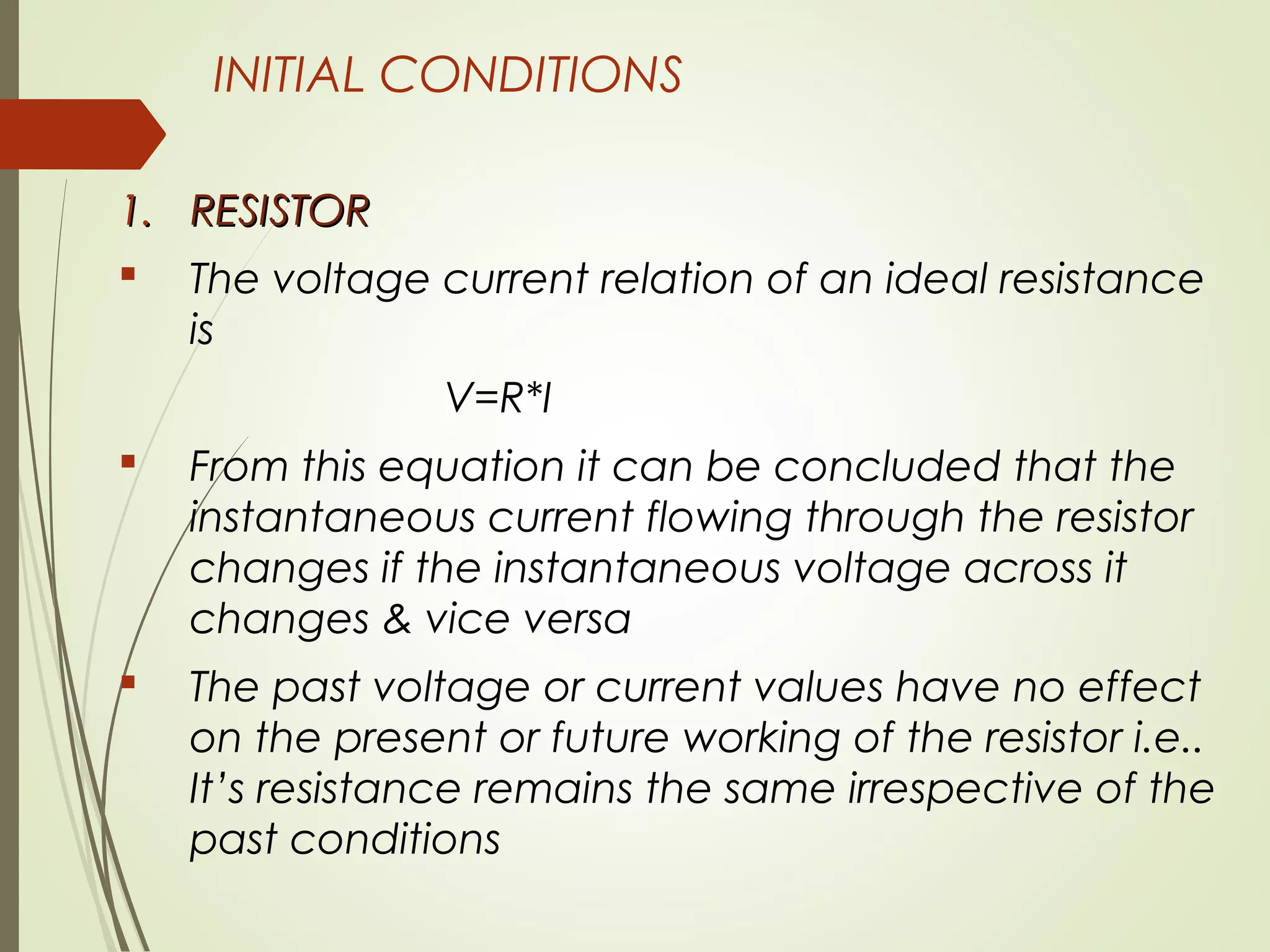
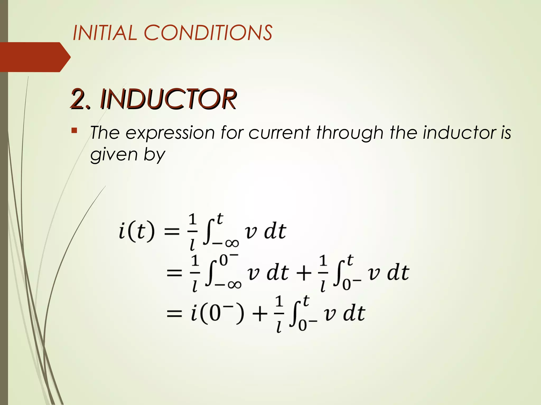
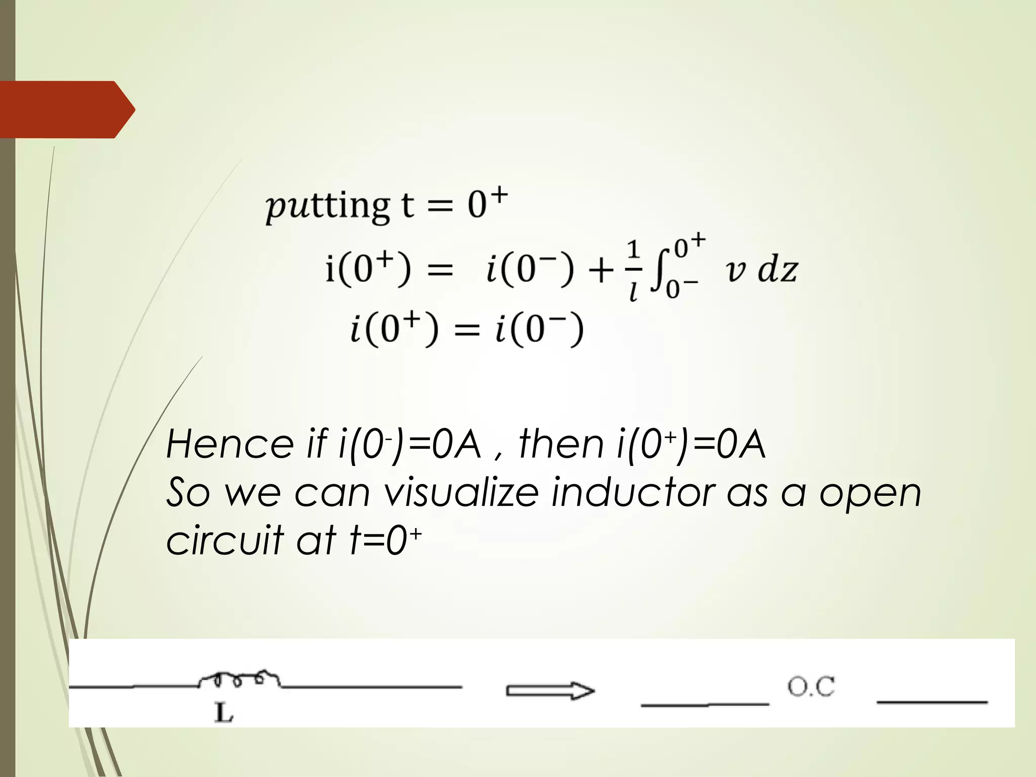
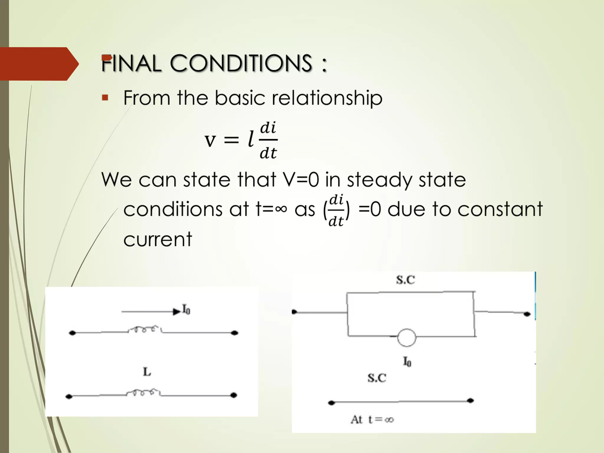
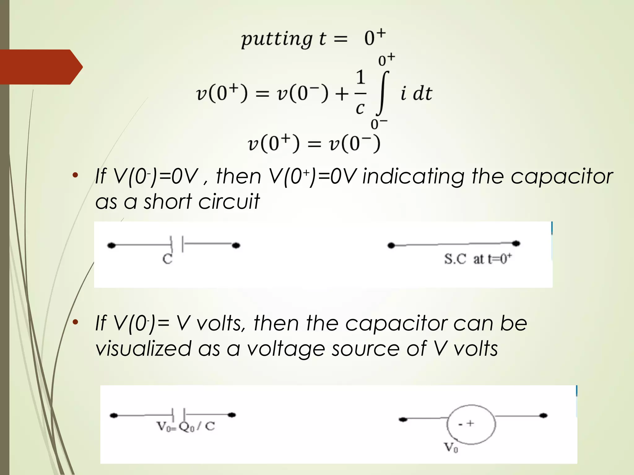
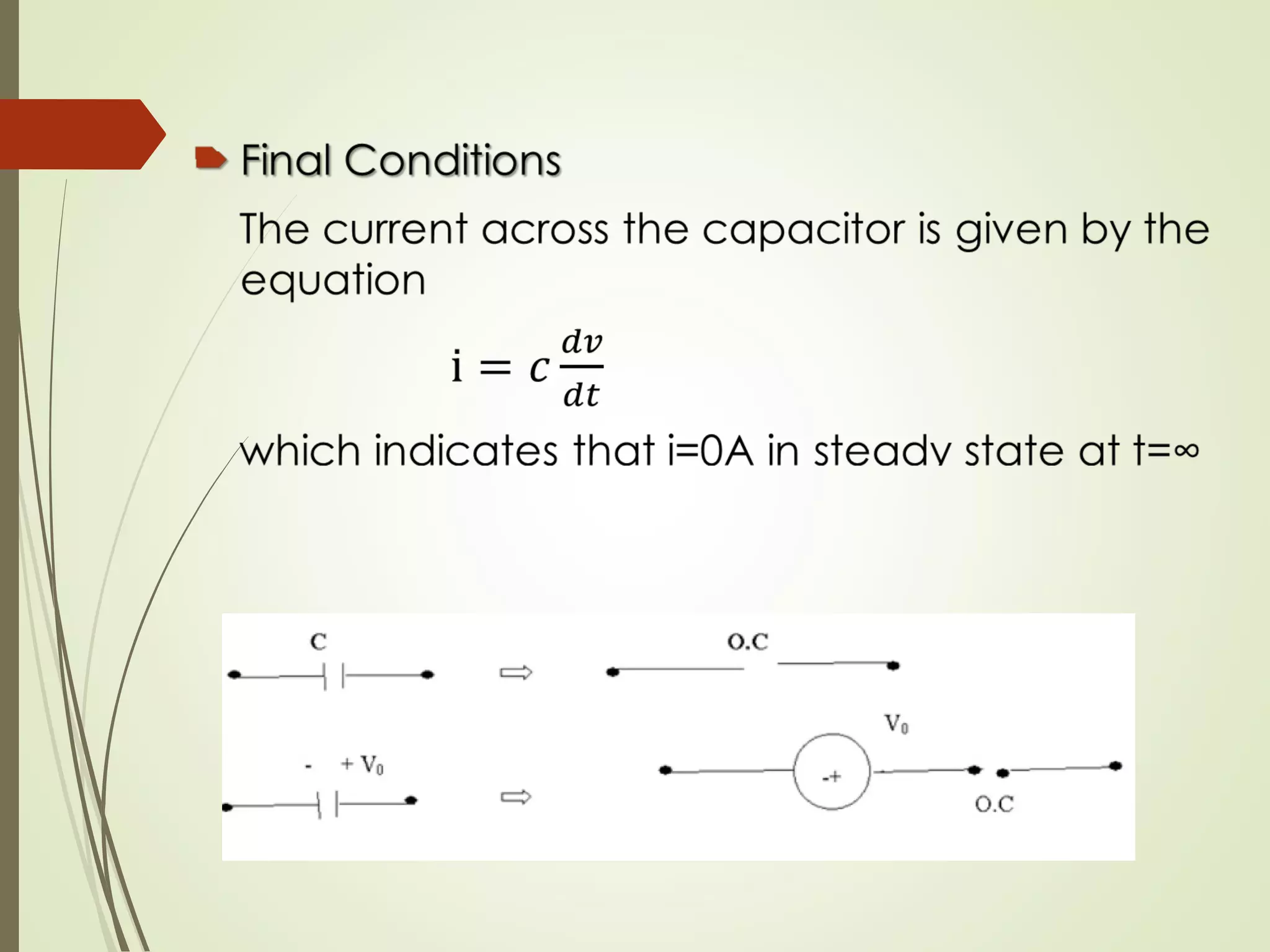
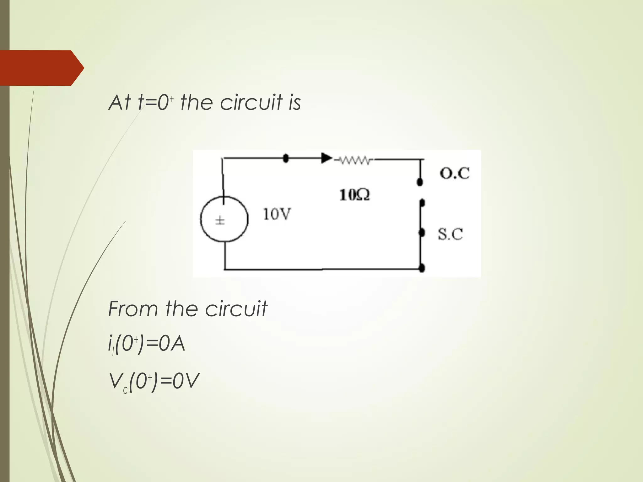
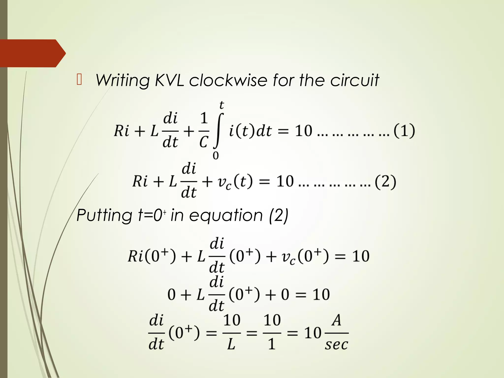
It then discusses the initial conditions for resistors, inductors, and capacitors when switches change, such as inductors behaving as open circuits or current sources, and capacitors behaving as short circuits or voltage sources. An example problem is included to demonstrate calculating initial conditions.
OPEN CIRCUIT AND SHORT CIRCUIT TEST OF SINGLE PHASE TRANSFORMER|DAY7| BASIC E...Prasant Kumar
#Open_circuit_short_circuit_test of single phase transformer
#OC_SC_TEST OF TRANSFORMER
#Core loss and copper loss test of single phase transformer.
After going through this session you will be able to answer the following questions.
• Which parameters are obtained from O.C test?
• Which parameters are obtained from S.C test?
• What percentage of rated voltage is needed to be applied to carry out O.C test?
• What percentage of rated voltage is needed to be applied to carry out S.C test?
• From which side of a large transformer, would you like to carry out O.C test?
• From which side of a large transformer, would you like to carry out S.C test?
Aim of conduction transformer Open Circuit & Short Circuit test
To predict its performance without actual loading.
Determination of equivalent circuit parameters
To determine parameters of a transformer like voltage regulation and efficiency
Open circuit test is carried out to determine core loss and shunt parameters.
Open circuit test is carried out at rated voltage and rated frequency . During this test, rated flux is produced in the core .
To carry out open circuit test rated voltage at rated frequency is applied to LV side of the transformer and HV side is left opened as shown in the circuit diagram.
HV side is left opened because it is easier to arrange rated voltage supply on LV side because no load current which is quite small about 2 to 5% of the rated current.
Metering instrument connected at LV side are economical & always safer to work.
The voltmeter, ammeter and the wattmeter readings are taken and suppose they are Voc , Io and Poc respectively.
Strictly speaking the wattmeter will record the core loss as well as the LV winding copper loss. But the winding copper loss is very small compared to the core loss as the flux in the core is rated.
Current sensing circuit based on an op-amp connected as a differential amplifier. This circuit is useful in designing power supplies or similar projects that needs current sensing function.
My instructables account: https://www.instructables.com/member/VEGEteK/
MY YOUTUBE CHANNEL: https://www.youtube.com/channel/UCXodUSRG2__hTpW4ZgOgtcw/
Electrical Engineering is the Branch of Engineering. Electrical Engineering field requires an understanding of core areas including Thermal and Hydraulics Prime Movers, Analog Electronic Circuits, Network Analysis and Synthesis, DC Machines and Transformers, Digital Electronic Circuits, Fundamentals of Power Electronics, Control System Engineering, Engineering Electromagnetics, Microprocessor and Microcontroller. Ekeeda offers Online Mechanical Engineering Courses for all the Subjects as per the Syllabus Visit : https://ekeeda.com/streamdetails/stream/Electrical-Engineering
Transients
Voltage surge or Transient Voltage
Types of Power System Transients
Causes of System transients
Overvoltage due to external causes
Overvoltage due to internal causes
Transients in Simple Circuit
D. C. Source & А.С. Source
Travelling Waves on Transmission Line
Wave equation
Travelling wave with open end line & Short Circuited Line
Reflection and Refraction Coefficient
Line Connected to a Cable
Line terminated Through Capacitance
Capacitor Connection at a T.L.
Attenuation of Travelling Waves
Electrical Engineering is the Branch of Engineering. Electrical Engineering field requires an understanding of core areas including Thermal and Hydraulics Prime Movers, Analog Electronic Circuits, Network Analysis and Synthesis, DC Machines and Transformers, Digital Electronic Circuits, Fundamentals of Power Electronics, Control System Engineering, Engineering Electromagnetics, Microprocessor and Microcontroller. Ekeeda offers Online Mechanical Engineering Courses for all the Subjects as per the Syllabus. Visit : https://ekeeda.com/streamdetails/stream/Electrical-and-Electronics-Engineering
An A.C. device used to change high voltage low current A.C. into low voltage high current A.C. and vice-versa without changing the frequency
In brief,
1. Transfers electric power from one circuit to another
2. It does so without a change of frequency
3. It accomplishes this by electromagnetic induction
4. Where the two electric circuits are in mutual inductive influence of each other.
Saudi Arabia stands as a titan in the global energy landscape, renowned for its abundant oil and gas resources. It's the largest exporter of petroleum and holds some of the world's most significant reserves. Let's delve into the top 10 oil and gas projects shaping Saudi Arabia's energy future in 2024.
Water scarcity is the lack of fresh water resources to meet the standard water demand. There are two type of water scarcity. One is physical. The other is economic water scarcity.
Sachpazis:Terzaghi Bearing Capacity Estimation in simple terms with Calculati...Dr.Costas Sachpazis
Terzaghi's soil bearing capacity theory, developed by Karl Terzaghi, is a fundamental principle in geotechnical engineering used to determine the bearing capacity of shallow foundations. This theory provides a method to calculate the ultimate bearing capacity of soil, which is the maximum load per unit area that the soil can support without undergoing shear failure. The Calculation HTML Code included.
Hybrid optimization of pumped hydro system and solar- Engr. Abdul-Azeez.pdffxintegritypublishin
Advancements in technology unveil a myriad of electrical and electronic breakthroughs geared towards efficiently harnessing limited resources to meet human energy demands. The optimization of hybrid solar PV panels and pumped hydro energy supply systems plays a pivotal role in utilizing natural resources effectively. This initiative not only benefits humanity but also fosters environmental sustainability. The study investigated the design optimization of these hybrid systems, focusing on understanding solar radiation patterns, identifying geographical influences on solar radiation, formulating a mathematical model for system optimization, and determining the optimal configuration of PV panels and pumped hydro storage. Through a comparative analysis approach and eight weeks of data collection, the study addressed key research questions related to solar radiation patterns and optimal system design. The findings highlighted regions with heightened solar radiation levels, showcasing substantial potential for power generation and emphasizing the system's efficiency. Optimizing system design significantly boosted power generation, promoted renewable energy utilization, and enhanced energy storage capacity. The study underscored the benefits of optimizing hybrid solar PV panels and pumped hydro energy supply systems for sustainable energy usage. Optimizing the design of solar PV panels and pumped hydro energy supply systems as examined across diverse climatic conditions in a developing country, not only enhances power generation but also improves the integration of renewable energy sources and boosts energy storage capacities, particularly beneficial for less economically prosperous regions. Additionally, the study provides valuable insights for advancing energy research in economically viable areas. Recommendations included conducting site-specific assessments, utilizing advanced modeling tools, implementing regular maintenance protocols, and enhancing communication among system components.
Cosmetic shop management system project report.pdfKamal Acharya
Buying new cosmetic products is difficult. It can even be scary for those who have sensitive skin and are prone to skin trouble. The information needed to alleviate this problem is on the back of each product, but it's thought to interpret those ingredient lists unless you have a background in chemistry.
Instead of buying and hoping for the best, we can use data science to help us predict which products may be good fits for us. It includes various function programs to do the above mentioned tasks.
Data file handling has been effectively used in the program.
The automated cosmetic shop management system should deal with the automation of general workflow and administration process of the shop. The main processes of the system focus on customer's request where the system is able to search the most appropriate products and deliver it to the customers. It should help the employees to quickly identify the list of cosmetic product that have reached the minimum quantity and also keep a track of expired date for each cosmetic product. It should help the employees to find the rack number in which the product is placed.It is also Faster and more efficient way.
Student information management system project report ii.pdfKamal Acharya
Our project explains about the student management. This project mainly explains the various actions related to student details. This project shows some ease in adding, editing and deleting the student details. It also provides a less time consuming process for viewing, adding, editing and deleting the marks of the students.
Industrial Training at Shahjalal Fertilizer Company Limited (SFCL)MdTanvirMahtab2
This presentation is about the working procedure of Shahjalal Fertilizer Company Limited (SFCL). A Govt. owned Company of Bangladesh Chemical Industries Corporation under Ministry of Industries.
2. INITIAL CONDITIONSINITIAL CONDITIONS
In Initial conditions, we find the change in
selected variables in a circuit when one or
more switches are moved from open to
closed positions or vice versa.
t=0-
indicates the time just before changing
the position of the switch
t=0 indicates the time when the position of
switch is changed
t=0+
indicates the time immediately after
changing the position of switch
3. INITIAL CONDITIONS
1.1. RESISTORRESISTOR
The voltage current relation of an ideal resistance
is
V=R*I
From this equation it can be concluded that the
instantaneous current flowing through the resistor
changes if the instantaneous voltage across it
changes & vice versa
The past voltage or current values have no effect
on the present or future working of the resistor i.e..
It’s resistance remains the same irrespective of the
past conditions
9. • If V(0-
)=0V , then V(0+
)=0V indicating the capacitor
as a short circuit
• If V(0-
)= V volts, then the capacitor can be
visualized as a voltage source of V volts
10.
11. EXAMPLE-1 :EXAMPLE-1 : In the network shown in the figure
the switch is closed at t=0. Determine i, (di/dt)
and (d2
i/dt2
) at t=0+
.
At t=0-
, the switch is Closed. Due to which
il(0-
)=0A
Vc(0-
)=0V