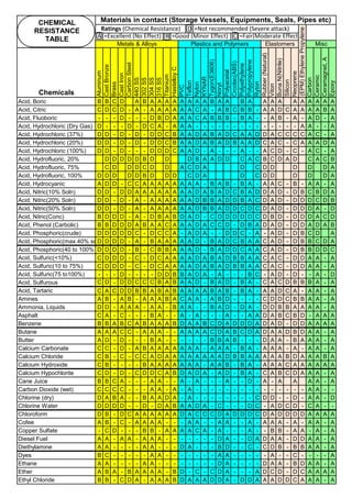
Downloaded 30 times


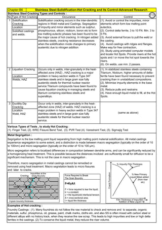
![Chapter-B3 Sensitization, Intergranular Attach, Weld Decay, Knifeline Attack Cures / Remedies
By JGC Annamalai
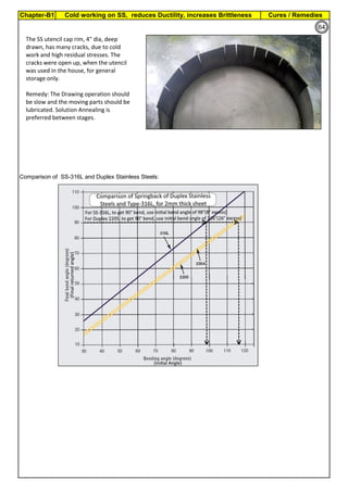
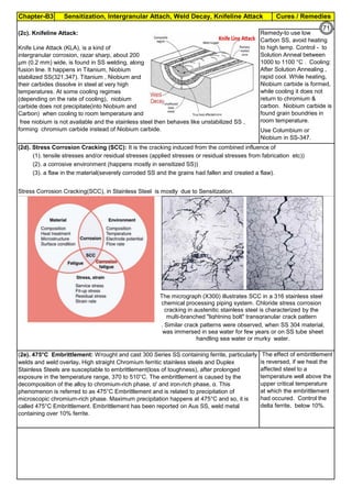
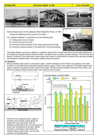
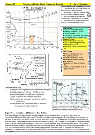
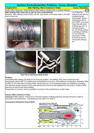
Sensitization and its Control:
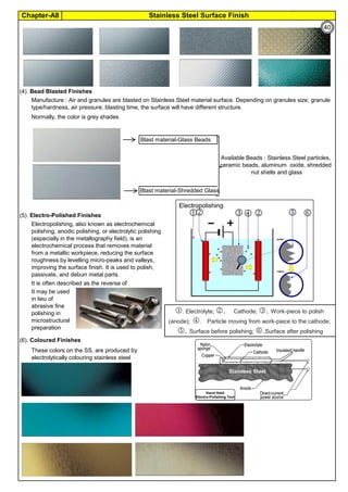
Derived Formula :
Controls & Revert Back to normal Stainless Steel :
Way
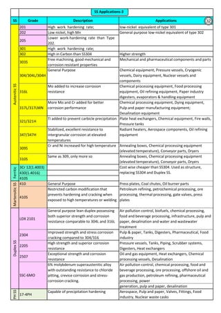
All ASTM material require Solution Annealing, after the forming operation. Sensitization may happen in : At (1).
Fabrication Shop, (2). at Heat Treatment Shop, (3). at Service, (4). earlier incomplete Solution annealing operation
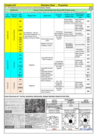
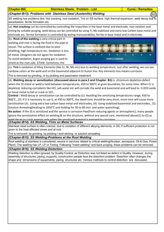
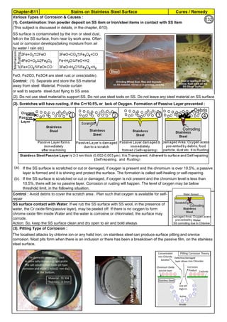
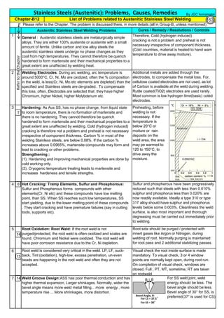
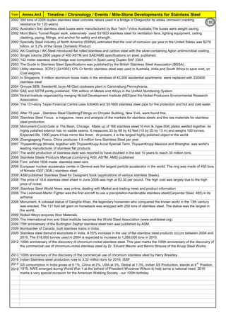
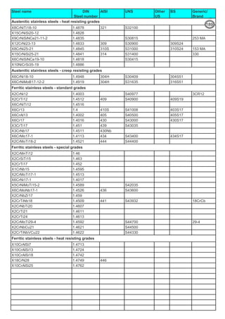
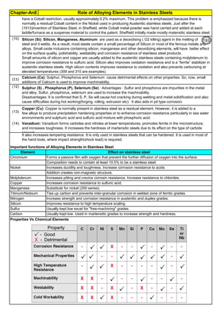
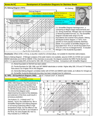
C, % Carbon in Stainless Steel. For SS304,
carbon is 0.08%
Measure of Sensitization: Susceptibility Test of SS to intergranular attack are described in ASTM A262
Temperature
Control
Practice A—Oxalic Acid Etch Test for Classification of Etch Structures of Austenitic Stainless Steels. The Oxalic
Acid Etch Test is used for acceptance of wrought or cast austenitic stainless steel material but not for rejection of
material. Use of A262 Practice A as a stand-alone test may reject material that the applicable hot acid test would
find acceptable;
Practice B—Ferric Sulfate-Sulfuric Acid Test for Detecting Susceptibility to Intergranular Attack in Austenitic
Stainless Steels. This practice describes the procedure for conducting the boiling 120-h ferric sulfate–50 % sulfuric
acid test which measures the susceptibility of austenitic stainless steels to intergranular attack.
Practice C—Nitric Acid Test for Detecting Susceptibility to Intergranular Attack in Austenitic Stainless Steels. This
practice describes the procedure for conducting the boiling nitric acid test as employed to measure the relative
susceptibility of austenitic stainless steels to intergranular attack.
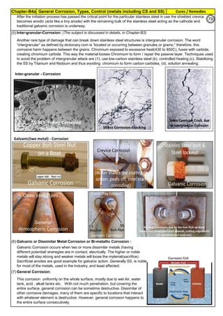
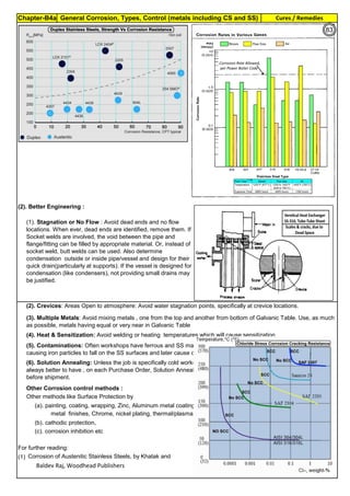
(1). All stainless steels, including Duplex SS, PH SS etc have chromium as their corrosion
resisting element. But, when the material is heated and / or kept at 425 to 950°C, they are
sensitized. In the corrosion environment, the stainless steel will corrode. (2). During cold
working, the grains are piled up and elangated. This results in high tensile stress, high
hardness and low elangation and low ductility. (3). During prolonged heating at 850 to 950°C,
the material changes to Sigma phase and during shut down or turn around, cooling below
250°C, the SS material start cracking. (4). As cast material surface has high hardness and
high strength at the surface, due to uneven temperature and asymmetical structure.
Sensitization, low ductility, Sigma formation etc are reversed or restored to normal annealed
condition, by heating to around 1050°C and rapid cooling. This is called full Solution
Annealing. Details on Solution Annealing, are found in Annexture-An2.
Sensitization, Cold Working,
Sigma formation etc are fully
reversed or restored to the
original grain, by full solution
annealing (say for SS304, at
1050°C). Solution Annealing
also makes SS soft, removes
magnetism and surface is
bright.
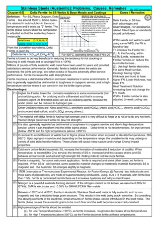
Sensitization is proprotional to
Temperature (normally SS-304
has low sensitization around
450°C and high sensitization
around 850°C)
Findings
FullSolutionAnnealingto
recoverChromium
0.02% is min. threshold limit for Carbon in Fe-C steel solid solution
(1). Extra Low Carbon SS: Use base metal and weld metal containing, as min. carbon as
possible like SS304L, SS316L(ASTM specify 0.03%C, but some Vendors offer 0.02% also)
(2). Stabilized SS: Use Titanium stabilized, SS321 or Niobium(Columbium or Tantalum)
stabilized SS347 as they have more affinity towards Carbon and they immediately form their
carbides, leaving Chromium free in the solid solution to form passive layer. Chromium Oxide
passive layer on the surface make the SS as corrosion resistance.
Control
CarbonControl
Stabilization
DwellTimeControl
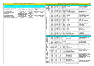
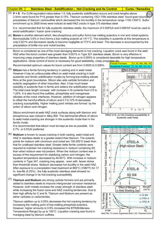
T, Sensitization Incubation Time (material
starting sensitization , in minute)
Time: For SS-304, Sensitization starts, just after 40 sec, when the material temperature is 800°C. Faster Cooling:
Cooling from 900 to 400°C, within 2 Minutes will produce negligible sensitization.
Solution Annealing Temperatures: For all SS grades, stainless steel must be cooled rapidly enough to avoid the
formation of secondary phases like Chromium Carbide(Cr23C6) which forms below about 900C(1650F). For High alloys,
the secondary phases will form at high temperatures. Chi phase is forming at 1095C(2000F). So the high alloys, must be
the Solution Annealed at high temperatures, say about 1095(2000F).
So, for process like Solution Annealing, the SS material,
should be fast cooled (for SS304,1.34 min) ie before
incubation start temperature, to 400°C.
Sensitization is proportional to
Carbon (SS-304 has 0.08%C.
It has high sensitization & SS-
304L has 0.03%C; has low
sensitization)
Keep the SS material, for a minimum time in the sensitizing temperature zone, during welding,
heating for rolling, forging, tube bending etc. Or take the temperature above sensitizing
temperature (say above 950°C). Often, after rolling, forging, hot bending etc operations are
done, heat the material to solution annealing temperature above 950°C. do rapid water
quench to reach black hot 400°C or below. Normal thick SS welding: Use heat sink, close to
weld. Welding Heat is = I
2
Rt Joules. Have intermittant welding. Often, allow weld to cool or
skip welding or back step welding or stagger welding.
Spot welds of SS thin sheets, current flows in milli seconds. No sensitization or corrosion is
noticed for several years. Incubation time is inversely proportional to Carbon %
Sensitization is proportional to
Dwelling Time (normally spot
welding of thin sheet, in 0.001
sec, has no sensitization;
Multilayer, High Energy
Welding, Heat Treatment etc.
has high sensitization)
Stainless steel is sensitized at temperature , 425 to 950°C. So, plan to avoid this temperature
range, during fabrication, construction and in plant operation. For forging, rolling, hot bending
etc operations, heat the piece, above 900°C and work. Do not stress relieve, in the sensitizing
range. For SS, Stress relieving is not preferred, but may be done, below 400°C (relieves
residual stresses 30 to 40%)
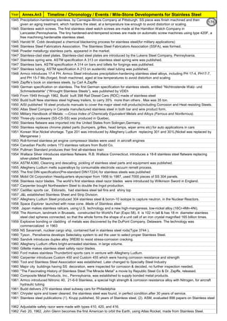
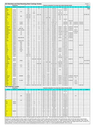
T=10((3.96-(47.92*C))
T=10^[3.96-(47.92*C)]
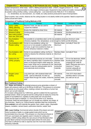
67](https://image.slidesharecdn.com/stainlesssteelsproblems-causes-remedies-200918150654/85/Stainless-Steels-Problems-Causes-Remedies-67-320.jpg)
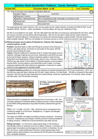
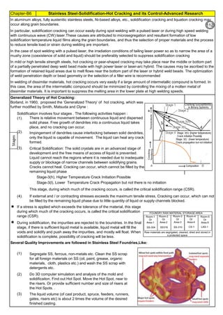
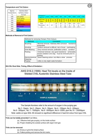
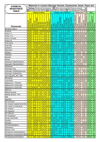
![Chapter-B3 Sensitization, Intergranular Attach, Weld Decay, Knifeline Attack Cures / Remedies
By JGC Annamalai
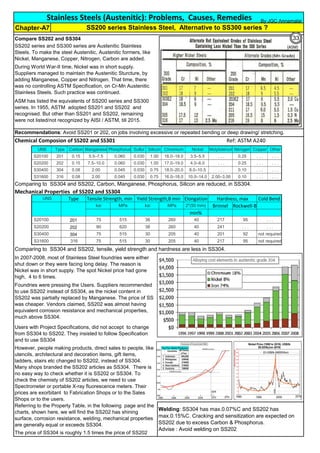
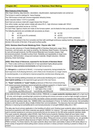
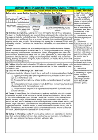
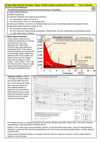
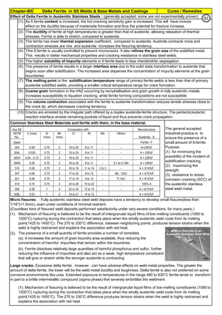
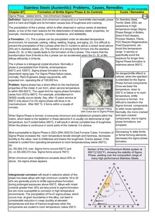
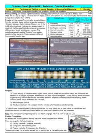
Definition: Weld Decay is Sensitization of Stainless Steel, during welding.
Recovery: Solution Annealing : Sensitization is removed or chromium is brought back to its original condition by Solution
Annealing heat treatment, carried out mostly at 1040°C or above. But this annealing should be done, before corrosion
start or before the grain starts separation / micro cracking. (Details on Solution Annealing is discribed in Annex. An2)
Practice F—Copper–Copper Sulfate–50 % Sulfuric Acid Test for Detecting Susceptibility to Intergranular Attack in
Molybdenum-Bearing Austenitic Stainless Steels. This practice describes the procedure for conducting the boiling
copper–copper sulfate–50 sulfuric acid test, which measures the susceptibility of stainless steels to inter- granular
attack.
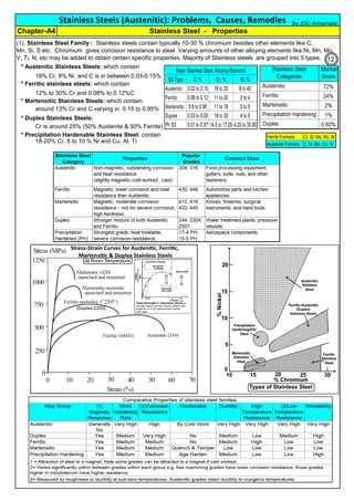
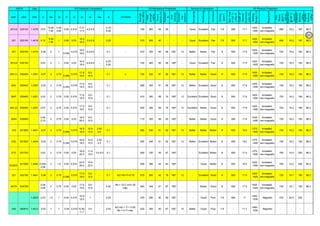
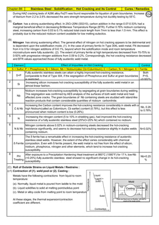
(2b). Weld Decay on SS Welds :
When unstabilized SS(304, SS316) are heated or cooled or in continuous service in
Sensitizing Zone (425°C to 870°C ), carbon at the grain boundaries combines with
chromium and forms chromium rich carbide (M23C6). Chromium depleted band(<10.5%Cr),
next to grain boundry, exhibits little corrosion resistance. Under certain corrosive conditions
intergranular corrosion attack takes place. This is called weld decay.
Practice E—Copper–Copper Sulfate–Sulfuric Acid Test for Detecting Susceptibility to Intergranular Attack in
Austenitic Stainless Steels. This practice describes the procedure by which the copper–copper sulfate–16 %
sulfuric acid test is conducted to determine the susceptibility of austenitic stainless steels to intergranular attack.
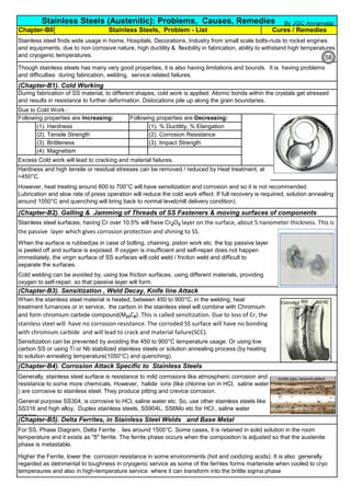
Corrosion: On sensitized stainless steels, the inside grains are protected by passive film [1
to 5 x 10
-6
mm(1 to 5 nm) thick] whereas the grain boundries are not protected. Corrosive
media may enter and corrode the grain boundry area, where Cr is depleted. Further the
grains and grain boundries have potional difference and this will set up a corrosive galvanic
cell and accelerate the corrosion.
Cooling:
(1). Keep copper bands/
plates, on the sides of the
weld so that the plate will
act as heat sink
(2). Without affecting the
weld/ weld groove, Cool
the area adjacent to weld
by other means like
keeping water soaked
sponge. (3). Use Dry Ice
(solid Carbon dioxide),
adjacent to the weld metal,
to cool the basemetal.
(4). Hot Rolling & Hot
Forging are done around
1100°C : After hot rolling or
hot forging , do Solution
annealing at 1050 to
1260°C ), immediately. (5).
Slow down the welding. Use
skip welding, back-step
welding or staggered
welding technique to avoid
heating (425°C to 870°C )
the basemetal.
68](https://image.slidesharecdn.com/stainlesssteelsproblems-causes-remedies-200918150654/85/Stainless-Steels-Problems-Causes-Remedies-68-320.jpg)
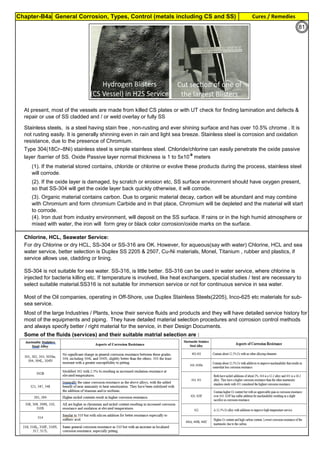
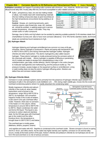
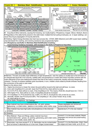
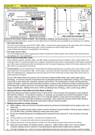

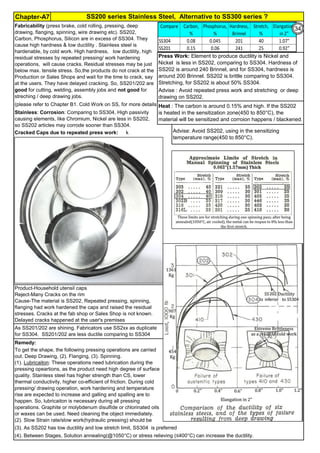
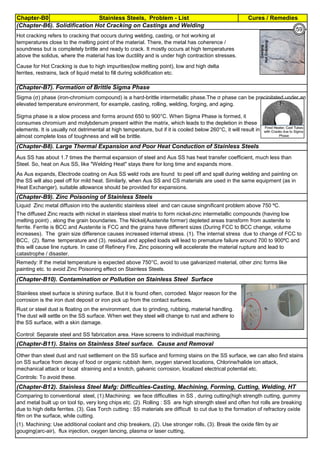
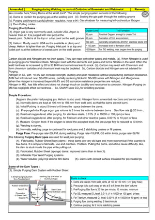
![Manufacturing of SS Products (by m/c, Forging, Forming, Cutting, Welding etc.)Chapter-B12
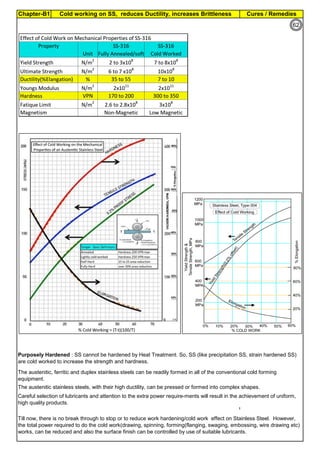
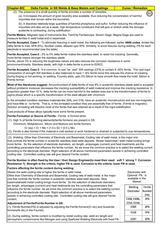
Type 304 is forged between 2300 ºF and 1700 ºF
(1260ºC and 930 ºC) and air cooled
Some Forging Type
Forging Temperature,
ºF(ºC)
Severe reductions (ingot breakdown, roll forging,
drawing, blocking, and backward extrusion)
2300 (1260)
Moderate reductions (finish forging and upsetting) 2200 (1200)
Slight reductions (coining, restriking and end
upsetting)
2050 (1120)
By JGC Annamalai
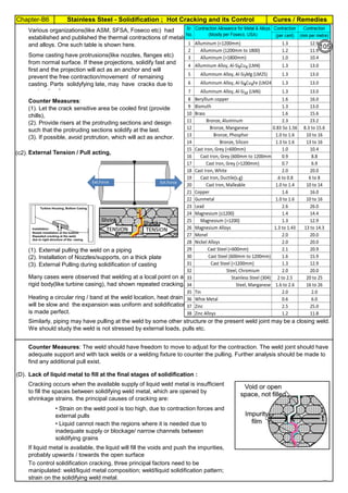
Chipis not breaking and
havevery long helicalCoil.
Gummy
Tip
SS material, has poor heat conduction.Heat is
buildingupat the tip. Tool Tip is blunted
Duringcutting, metal flows and cold work is
happening.Materialgets hardened and
strength increased. Tool finds difficult to cut
SS
Material
( D) . SS Metal Cutting / Parting
Traditional Cutting:
(A2). Abrasive grinding wheels are used to cut, from 20 - 100mm thick). Aluminium Oxide (Alumina) disc is recommed.
(A5). Oxy-Acetylene flame can be used to cut mild steel in the 3–1000 mm thickness range, cutting speeds are 5–15
cm/min.. The equipment is light and easy to set up.
Heavy cutting(300 mm to 1525mm) on Steel, is possible using Heavy Duty Oxy-Acetylene cutting torches. Always, do
experiment and do trial runs before starting "First time works".
Oxy-Acetylene flame cannot cut Stainless Steel , Aluminum etc refractory oxide producing materials, as the refractory
does not melt by Oxy-Acetylene flame temperature.
(4). Nickel price in October 2001 – was under $5,000/ton and it peaked in May 2007 at US$50,000/ton. In 2011, the
Nickel price was around $20,000/ton.
Around 2007, the Nickel was having shortage and Foundries were buying Nickel / ferro-nickel at exorbitant price, for
their use. Almost all Stainless Steel foundries did not have AOD or VOD Furnace to refine. Though Nitrogen and
manganese were established as an alternative to Nickel to maintain Austenitic structure, Users specifications were
rigid and the users did not agree to replace nickel by nitrogen or manganese, when there was Nickel shortage.
(A3). Sawing of Austenitic grades (300 Series) is made more difficult due to their tendency to work harden. In cutting
these grades the cut must be initiated without any riding of the saw on the work, a positive feed pressure must be
maintained, and no pressure, drag or slip should occur on the return stroke.
(A4). Shear or Press Brake: SS plates of thickness below 6 mm are shear cut. The die and punch tools should
produce minimum gap so that due to bending, not much work hardening takes place.
The following cutting processes are used to cut Aus SS: (1). Traditional Cutting, (2). Non Traditional Cutting.
(5). Steel mills or stainless steel mills normally have continuous casting unit and the cast product is immediately rolled
into different sections or plates/strips. But stainless steel foundries have different shapes, different thicknesses and
often the product is hollow. Each product needs study (better methoding) before pouring. Normally 50 to 100% extra
liquid stainless steel metal is poured to account for raisers, feeders, runners, pads etc(which are cut & scrapped).
(6). Further if sections of the casting are restrained, the shrinkage stresses can cause hot tears, particularly at changes
of section size and profile. So, to avoid hot tears, foundries often go for (a). a gradual change of cross section, (b).
Large radii at change of profile , (c). Inducing directional cooling, by providing chillers.
(7). To compensate the loss of some elements by oxidation (melting, pouring etc operations are slow and surface area
at the furnace, at the ladle and at the mould are large and open to atmosphere, the critical elements tend to oxidize)
during the casting process, modification of the furnace mix or addition of additional quantities of chromium, nickel are
necessary.
[1]. Traditional(Old): Machine Cutting: (a). Shear and Press Brake cutting, Abrasive Grinding Wheel cutting, Band
Saw & Power Saw cutting, Cutting by m/c tools(like lathe, milling & planning m/c), (b). Thermal Cutting: Carbon Arc-
Air Gouging, Oxygen Lance Cutting, O2 Oxy Acetylene flame with Iron Powder or Iron Powder + Aluminum Powder
Injection Cutting & Flux Injection Cutting.
[2]. Non-Traditional(Recent) : Water Jet Cutting, Laser Cutting, Plasma cutting, EDM
(A1). Shop Entry cutting : At the entry of the Shop process, most of the workshop, have Band Sawing or Power
Hacksawing or Abrasive wheel Cutting machines, to cut stocks to be used in the Shop. These machines can cut Aus
SS.
Cost in US$ per Ton
Pg.B10.1
94
142](https://image.slidesharecdn.com/stainlesssteelsproblems-causes-remedies-200918150654/85/Stainless-Steels-Problems-Causes-Remedies-142-320.jpg)
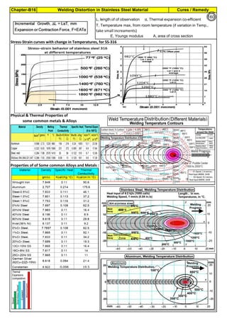
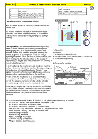
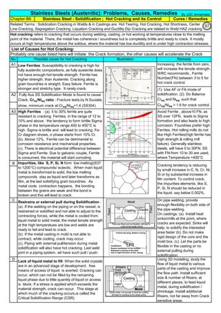
![Solution Annealing of Austenitic Stainless SteelsAnnex-An2
By JGC Annamalai
3
4
Time Management :
ASTM specifies the Temperature. But the duration of annealing is not specified. The Vendor has to establish
the following timings: (from earlier works, from other's work, or from a sample study)
Austenitic SS: Solution Annealing : The austenitic alloys achieve maximum resistance to intergranular corrosion by
the high temperature heating and quenching procedure known as solution annealing. As-cast structures, or castings
exposed to temperatures in the range from 425 to 870°C (800 to 1600°F), may contain complex chromium carbides
precipitated preferentially along grain boundaries in wholly austenitic alloys. This microstructure is susceptible to
intergranular corrosion, especially in oxidizing solutions. (In partially ferritic alloys, carbides tend to precipitate in the
discontinuous ferrite pools; thus, these alloys are less susceptible to intergranular attack.) The purpose of solution
annealing is to ensure complete solution of carbides in the matrix and to retain these carbides in solid solution.
Solution-annealing procedures for all austenitic alloys are similar, and consist of heating to a temperature of about
1095°C (2000°F), holding for a time sufficient to accomplish complete solution of carbides, and quenching at a rate
fast enough to prevent reprecipitation of the carbides--particularly while cooling through the range from 870 to 540°C
(1600 to 1000°F). Temperatures to which castings should be heated prior to quenching vary somewhat, depending on
the alloy.Niobium statbilized SS: Stabilizing Treatment. As shown in Table 16, a two-step heat-treating procedure may be
applied to the niobium containing CF-8C (UNS J92710) alloy. The first treatment consists of solution annealing. This is
followed by a stabilizing treatment at 870 to 925°C (1600 to 1700°F), which precipitates niobium carbides, prevents
formation of the damaging chromium carbides, and provides maximum resistance to intergranular attack.
As cast stainless steel, is hard to grind or to machine, as complex phases exist. Inside the mold,
the temperature is not controlled. Possibilities are that chromium carbides should have already
formed. This situation requires, solution annealing on the castings to soften the castings and to
remove chromium carbides.
Alloy segregation and dendritic structures may occur in castings and may be particularly pronounced as
the metal pass through the sensitization range. Most of the pressure vessel casting specification
require solution anealing on the castings. Alloy segregation and dendritic structures may occur in
castings and may particularly pronounced in heavy sections. It is frequently necessary in the Castings,
to homogenize alloy castings at temperatures above 1095°C (2000°F) to promote uniformity of chemical
composition and microstructure
Vendor /Sub-Vendor should consult and prepare the Solutional Annealing Procedure shall be made, to meet the ASTM
or applicable Specification Requirements.
ASTM says, the heat-treatment procedure, shall consist of solution annealing the components at a minimum temperature
of 1900°F [1040°C] until the chromium carbides go into solution, and then cooling at a sufficient rate to prevent carbide
re-precipitation. The dwell time at the solution annealing furnace is about 30 minutes. It varies depending up on the
thickness.
(1). The duration of solution annealing treatment, inside the furnace
(2). time taken from furnace to water tank
(3). how fast the black temperature (400°C) is reached
As the manufactured objects are often unique and the Vendor has to establish and to incorporate the timings, into their
Procedure. ASTM A262 test shall be conducted on test samples to find any sensitization left/the carbides have gone fully
to Solid Solution. The production Procedure should include, such timings(heat treatment time, transfer time to tank,
cooling rate time etc).To do the trial run, Expected or Tentative Time may be taken from other references, like AMS
2759/4B, Heat Treatment of Austenitic Corrosion-Resistant Steel Parts, in addition to Vendor experience.
Normally the time taken from oven to reach the the 400°C, in the quench tank, is 2 minutes.
Because of their low carbon contents, CF-3 and CF-3M (UNS J92700 and J92800) as-cast do not contain enough
chromium carbides to cause selective intergranular attack, and hence they may be used in some corrodents in this
condition; for maximum corrosion resistance, however, these grades require solution annealing.
Solution Annealing Procedure (as per ASM) : Vendor to Prepare Detailed Procedure (with stage Timing) :
ASTM Requirements: All most all cast, formed, extruded, spinned, drawn shapes require solution
annealing per ASTM. Majoritity of the material is supplied as "Annealed".
119
167](https://image.slidesharecdn.com/stainlesssteelsproblems-causes-remedies-200918150654/85/Stainless-Steels-Problems-Causes-Remedies-167-320.jpg)
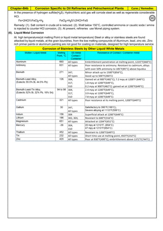
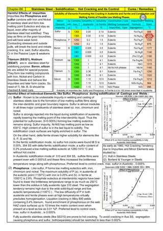
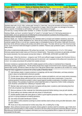
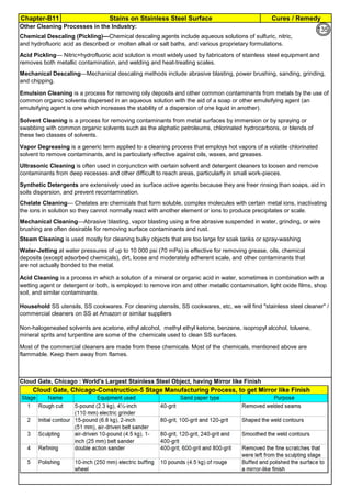
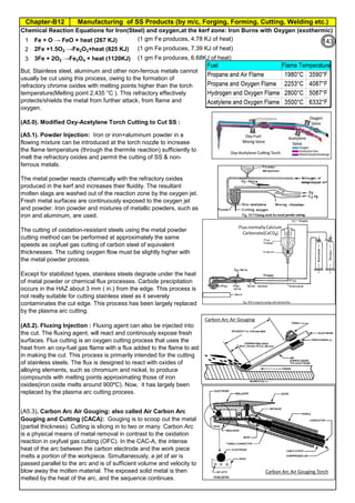
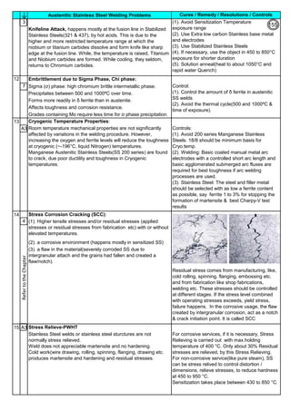
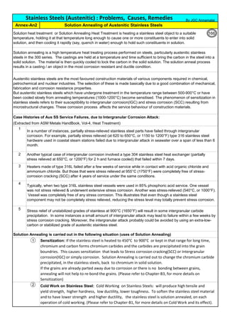
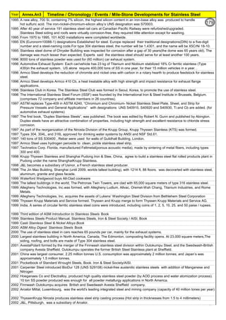
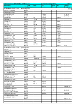
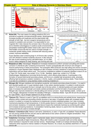
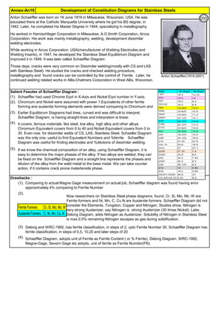
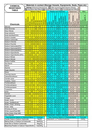
![Solution Annealing of Austenitic Stainless SteelsAnnex-An2
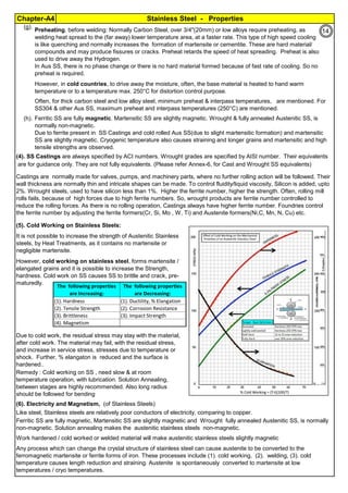
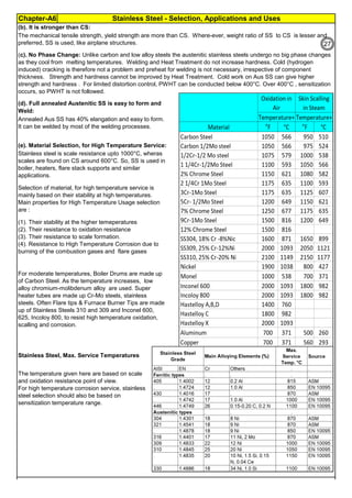
By JGC Annamalai
Seamless&WeldedPipe
General,ASM
Forgings
Solution
Annealing
Temperatures
Grade Heat Treat Type
Austenitizing/
solutioning
Temperature,
min °F (°C)
Cooling
Media
Quenching
Cool, Below,
°F (°C)
Tempering
Temperature,
min °F (°C)
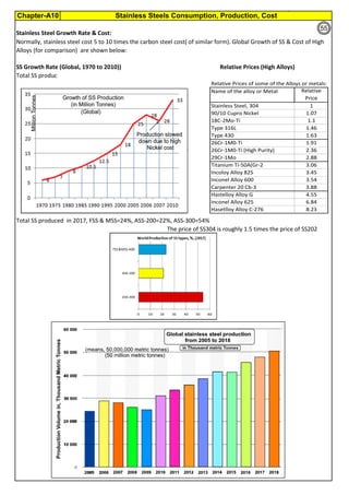
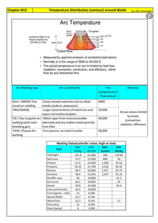
F 304 solution treat and quench 1900 [1040] liquid 500 [260] B
F 304H solution treat and quench 1900 [1040] liquid 500 [260] B
F 304L solution treat and quench 1900 [1040] liquid 500 [260] B
F 304N solution treat and quench 1900 [1040] liquid 500 [260] B
F 304LN solution treat and quench 1900 [1040] liquid 500 [260] B
F 309H solution treat and quench 1900 [1040] liquid 500 [260] B
F 310 solution treat and quench 1900 [1040] liquid 500 [260] B
F 310H solution treat and quench 1900 [1040] liquid 500 [260] B
F 310MoLn solution treat and quench
1900–2010
[1050–1100]
liquid 500 [260] B
F 316 solution treat and quench 1900 [1040] liquid 500 [260] B
F 316H solution treat and quench 1900 [1040] liquid 500 [260] B
F 316L solution treat and quench 1900 [1040] liquid 500 [260] B
F 316N solution treat and quench 1900 [1040] liquid 500 [260] B
F 316LN solution treat and quench 1900 [1040] liquid 500 [260] B
F 317 solution treat and quench 1900 [1040] liquid 500 [260] B
F 317L solution treat and quench 1900 [1040] liquid 500 [260] B
F 347 solution treat and quench 1900 [1040] liquid 500 [260] B
F 347H solution treat and quench 2000 [1095] liquid 500 [260] B
F 348 solution treat and quench 1900 [1040] liquid 500 [260] B
F 348H solution treat and quench 2000 [1095] liquid 500 [260] B
F 321 solution treat and quench 1900 [1040] liquid 500 [260] B
F 321H solution treat and quench 2000 [1095] liquid 500 [260] B
F XM-11 solution treat and quench 1900 [1040] liquid 500 [260] B
F XM-19 solution treat and quench 1900 [1040] liquid 500 [260] B
(BmeansNotApplicable)
A 182/A 182M,
Heat Treating Requirements
TheseASTM&ASMSpecdonotspecify
anyTimelimitforobjecttransferor
soakingetc.VendortodetermineTimeso
thatnosensitizationhappen/remainand
preparetheSolutionAnnealing
Procedure
Piping Components to ASM / ASTM
168](https://image.slidesharecdn.com/stainlesssteelsproblems-causes-remedies-200918150654/85/Stainless-Steels-Problems-Causes-Remedies-168-320.jpg)
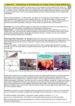
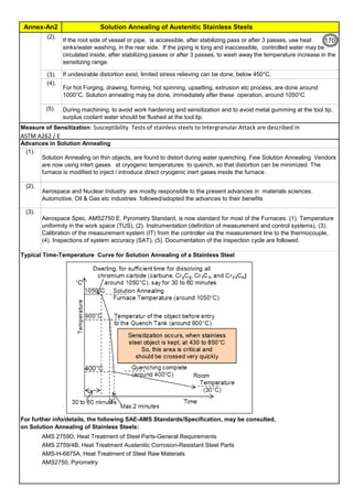
![Solution Annealing of Austenitic Stainless SteelsAnnex-An2
By JGC Annamalai
Difficulties faced during Solution Annealing of Stainless Steel objects at Vendor Shop :
Difficulties faced for Solution Annealing at Site / Fab Shop :
(1).
(2).
(3).
Carbon Control:
1 Use low Carbon Stainless steels materials(plates & Electrodes etc) like, 304L, 316L and 308L, 316L
2
Time Control:
1
Temperature Control:
(1).
6
Use stabilized stainless steel type-321 and 347.
Buy and use fully annealed plates and shapes for fabrication.
5
4
Residual Stress: Rapid cooling will re-introduce residual stresses, which could be as high as the yield point.
Distortion can also occur if the object is not properly supported during the annealing process.
Transfer Time from Furnace to Water Tank: Large and heavy objects are difficult to transport and rapid cool
in Water Tank, within the specified transfer time. Time limitation is based on sensitization time)
Knowing such difficulties, Engineers often go for alternative methods, to avoid solution annealing at the end.
3
2
High Temperature Risk: The solution annealing temperatures are very high, say, 1000 to 1150°C. Handling
objects and transfering the objects to water tank to quench, has high temperature risk.
1
There are cases, solution annealing is not possible or near impossible. However, to meet the code requirement or to
avoid sensition and other bad effects due to heat, the following alternatives are taken:
The object, like large pressure vessels, reactors are large in size and difficult to handle or have such large
quench tank and controls.
Fabricated piping, inside a plant often have complex configuration and sometime the length runs more than 1 km.
Vessels and heat exchangers are constructed using different type of metals and materials and normally, their
property does not allow to have water quenching.
Longer the duration at the sensitizing temperature, larger the sensitization. Electric Spot welding of thin
301 stainless steel sheets, in less than 5 milliseconds, is found to cause no sensitization. There was no
corrosion , even after 30 years of operation.
During Welding: Eletrical Energy = I2
Rh, the energy is proportional to square of Current and so reduce
current flow through the electrode. Use smaller size electrodes. Control and maintain Interpass
temperature below 175°C. Have number of small passes/stringer beads to complete the welding. Use
Skip welding and backstep welding. During welding, have heat sink(copper plates, water soaked cloths
etc) next to weld and save the weld HAZ from sensitization.
Steam Forming and steam effect: High temperature of the object, immediately makes the water to steam.
Heat Transfer in the medium of Steam is much less and this may retard the heat transfer and cooling rate
may be slow and sensitization may appear again. Allowing water inside the closed vessel produce steam.
Pressure may increase, if there is no vent point.
Difficult to Keep the Shape: The stainless steel material stress at annealing temperatures(1000 to 1150°C), is
near to yield strength. Lifting, transfering may deform the shape. Possibilities are more that the object may
deform due to its own weight. Additional supporting , using SS310 and/or SS309 and/or refractory Brick is
necessary.
Floating: Some fabricated vessels, may float on the water due to buoyancy. Additional dead weight may be
added to the vessel supporting structure, to counter the buoyancy/floating effect.
Castings
WroughtFittings
ASTM A403, Wrought Type,
Heat Treatment, Annealing
Solution
Annealing @
Grades 321H, 347H, and 348H 1050°C min
Grades 321, 321H, 347, and 347H 1150°C max
All other Au SS Grades 1040°C min
F 321 solution treat and quench 1900 [1040] liquid 500 [260] B
F 321H solution treat and quench 2000 [1095] liquid 500 [260] B
F XM-11 solution treat and quench 1900 [1040] liquid 500 [260] B
F XM-19 solution treat and quench 1900 [1040] liquid 500 [260] B
169](https://image.slidesharecdn.com/stainlesssteelsproblems-causes-remedies-200918150654/85/Stainless-Steels-Problems-Causes-Remedies-169-320.jpg)
![ASTM
Standards
Stainless Steels related ASTM Standards, Title
By JGC Annamalai
Annex.
An.4 132
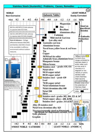
ASTM A564/A564M Standard Specification for Hot-Rolled and Cold-Finished Age-Hardening Stainless Steel Bars
and Shapes
ASTM A565/A565M Standard Specification for Martensitic Stainless Steel Bars for High-Temperature Service
ASTM A580/A580M Standard Specification for Stainless Steel Wire
ASTM A581/A581M Standard Specification for Free-Machining Stainless Steel Wire and Wire Rods
ASTM A582/A582M Standard Specification for Free-Machining Stainless Steel Bars
ASTM A609/A609M Standard Practice for Castings, Carbon, Low-Alloy, and Martensitic Stainless Steel, Ultrasonic
Examination Thereof
ASTM A632 Standard Specification for Seamless and Welded Austenitic Stainless Steel Tubing (Small-
Diameter) for General Service
ASTM A666 Standard Specification for Annealed or Cold-Worked Austenitic Stainless Steel Sheet, Strip, Plate,
and Flat Bar
ASTM A688/A688M Standard Specification for Seamless and Welded Austenitic Stainless Steel Feedwater Heater
Tubes
ASTM A693 Standard Specification for Precipitation-Hardening Stainless and Heat-Resisting Steel Plate, Sheet,
and Strip
ASTM A705/A705M Standard Specification for Age-Hardening Stainless Steel Forgings
ASTM A733 Standard Specification for Welded and Seamless Carbon Steel and Austenitic Stainless Steel Pipe
Nipples
ASTM A747/A747M Standard Specification for Steel Castings, Stainless, Precipitation Hardening
ASTM A756 Standard Specification for Stainless Anti-Friction Bearing Steel
ASTM A763 Standard Practices for Detecting Susceptibility to Intergranular Attack in Ferritic Stainless Steels
ASTM A774/A774M Standard Specification for As-Welded Wrought Austenitic Stainless Steel Fittings for General
Corrosive Service at Low and Moderate Temperatures
ASTM A778/A778M Standard Specification for Welded, Unannealed Austenitic Stainless Steel Tubular Products
ASTM A789/A789M Standard Specification for Seamless and Welded Ferritic/Austenitic Stainless Steel Tubing for
General Service
ASTM A790/A790M Standard Specification for Seamless and Welded Ferritic/Austenitic Stainless Steel Pipe
ASTM A793 Standard Specification for Rolled Floor Plate, Stainless Steel
ASTM A799/A799M Standard Practice for Steel Castings, Stainless, Instrument Calibration, for Estimating Ferrite
Content
ASTM A803/A803M Standard Specification for Seamless and Welded Ferritic Stainless Steel Feedwater Heater Tubes
ASTM A813/A813M Standard Specification for Single- or Double-Welded Austenitic Stainless Steel Pipe
ASTM A814/A814M Standard Specification for Cold-Worked Welded Austenitic Stainless Steel Pipe
ASTM A815/A815M Standard Specification for Wrought Ferritic, Ferritic/Austenitic, and Martensitic Stainless Steel
Piping Fittings
ASTM A838 Standard Specification for Free-Machining Ferritic Stainless Soft Magnetic Alloy Bar for Relay
Applications
ASTM A872/A872M Standard Specification for Centrifugally Cast Ferritic/Austenitic Stainless Steel Pipe for Corrosive
Environments
ASTM A887 Standard Specification for Borated Stainless Steel Plate, Sheet, and Strip for Nuclear Application
ASTM A895 Standard Specification for Free-Machining Stainless Steel Plate, Sheet, and Strip
ASTM A908 Standard Specification for Stainless Steel Needle Tubing
ASTM A923 Standard Test Methods for Detecting Detrimental Intermetallic Phase in Duplex Austenitic/Ferritic
Stainless Steels
ASTM A928/A928M Standard Specification for Ferritic/Austenitic (Duplex) Stainless Steel Pipe Electric Fusion Welded
with Addition of Filler Metal
ASTM A941 Standard Terminology Relating to Steel, Stainless Steel, Related Alloys, and Ferroalloys
ASTM A943/A943M Standard Specification for Spray-Formed Seamless Austenitic Stainless Steel Pipes
ASTM A947M Standard Specification for Textured Stainless Steel Sheet [Metric]
ASTM A949/A949M Standard Specification for Spray-Formed Seamless Ferritic/Austenitic Stainless Steel Pipe
ASTM A955/A955M Standard Specification for Deformed and Plain Stainless-Steel Bars for Concrete Reinforcement
182](https://image.slidesharecdn.com/stainlesssteelsproblems-causes-remedies-200918150654/85/Stainless-Steels-Problems-Causes-Remedies-182-320.jpg)

The document provides an extensive overview of austenitic stainless steels, detailing their history, properties, production, and applications, along with issues and challenges faced in their usage and fabrication. It covers topics ranging from the discovery of stainless steel to its role in modern engineering and architecture, highlighting its corrosion resistance and varied structural uses. Additionally, the document includes a comprehensive list of chapters discussing various aspects of stainless steel, including problems, causes, remedies, and annexures related to stainless steel compositions and processes.


