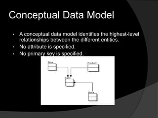
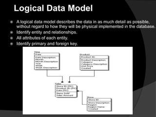
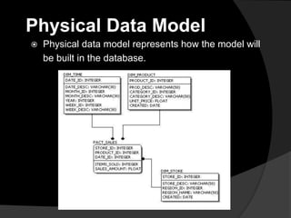
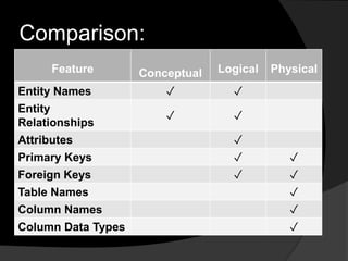
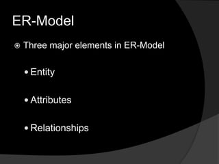
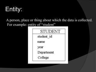
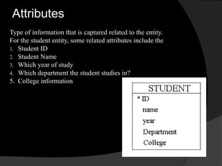
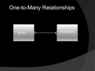
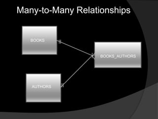
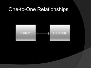
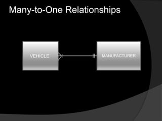
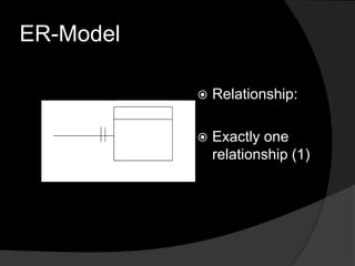
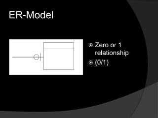
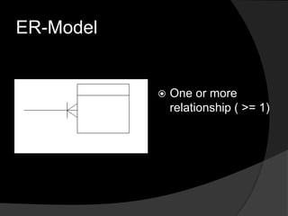
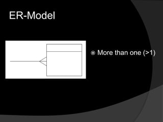
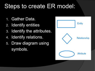
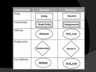
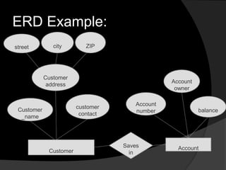
AND ER MODELS
Data Modeling
 The analysis of data objects and their relationships
to other data objects.
 Data modeling is often the first step in creating a
database
 The designers first create a conceptual model of
how data items relate to each other.
Data modeling involves a progression from
conceptual model to logical model to physical
model.
Levels of data modeling:
 There three level of data modeling,
conceptual data model,
 logical data model, and
 physical data model,
Conceptual Data Model
• A conceptual data model identifies the highest-level
relationships between the different entities.
• No attribute is specified.
• No primary key is specified.
Logical Data Model
 A logical data model describes the data in as much detail as possible,
without regard to how they will be physical implemented in the database.
 Identify entity and relationships.
 All attributes of each entity.
 Identify primary and foreign key.
Physical Data Model
 Physical data model represents how the model will
be built in the database.
Comparison:
Feature Conceptual Logical Physical
Entity Names ✓ ✓
Entity
Relationships
✓ ✓
Attributes ✓
Primary Keys ✓ ✓
Foreign Keys ✓ ✓
Table Names ✓
Column Names ✓
Column Data Types ✓
Entity-Relationship Model
 In software engineering, an entity-relationship
model (ER Model) is an conceptual representation
of data.
 Entity-relationship modeling is a database modeling
method, used to produce a type of conceptual
schema of a system, often a relational database.
 Diagrams created by this process are called entity-
relationship diagrams, ER diagrams, or ERDs.
ER-Model
 Three major elements in ER-Model
 Entity
 Attributes
 Relationships
Entity:
A person, place or thing about which the data is collected.
For example: entity of “student”
Attributes
Type of information that is captured related to the entity.
For the student entity, some related attributes include the
1. Student ID
2. Student Name
3. Which year of study
4. Which department the student studies in?
5. College information
Relationship
 A relationship is an association or bond
that exists between one or more entities.
 For example :
 Belongs to, own, works for, saves in,
purchases and so on
There are three types of relationships
between tables. The type of relationship
that is created depends on how the
related columns are defined.
 One-to-Many Relationship
 Many-to-Many Relationships
 One-to-One Relationships
 Many-to-One Realtionships
Relationship
One-to-Many Relationships
 A one-to-many relationship is the most
common type of relationship. In this type of
relationship, a row in table A can have
many matching rows in table B, but a row
in table B can have only one matching row
in table A.
 For example, the PUBLISHERS and
BOOKS tables have a one-to-many
relationship: each publisher produces
many titles, but each title comes from only
one publisher.
BOOKS PUBLISHER
One-to-Many Relationships
Many-to-Many Relationships
 In a many-to-many relationship, a row in table A
can have many matching rows in table B, and
vice versa.
 For example, the AUTHORS table and the
BOOKS table have a many-to-many
relationship that is defined by a one-to-many
relationship from each of these tables.
BOOKS
BOOKS_AUTHORS
AUTHORS
Many-to-Many Relationships
One-to-One Relationships
 In a one-to-one relationship, a row in table
A can have no more than one matching
row in table B, and vice versa. A one-to-
one relationship is created if both of the
related columns are primary keys or have
unique constraints.
 This type of relationship is not common
because most information related in this
way would be all in one table.
PERSON LOCATION
One-to-One Relationships
Many-to-One Relationships
 In a many-to-one relationship, one or more
row in table A can have no more than one
matching row in table B.
 For example, many vehicle are
manufactured by one manufacturer.
Many-to-One Relationships
VEHICLE MANUFACTURER
ER-Model
 Relationship:
 Exactly one
relationship (1)
ER-Model
 Zero or 1
relationship
 (0/1)
ER-Model
 One or more
relationship ( >= 1)
ER-Model
 More than one (>1)
Steps to create ER model:
1. Gather Data.
2. Identify entities
3. Identify the attributes.
4. Identify relations.
5. Draw diagram using
symbols.
Entity-Relationship Diagrams
 The E-R diagram is a graphical
representation of the E-R model.
 The symbols used for the various
components can be seen in the
following table:
ERD Example:
street city ZIP
Customer
address
Customer
_name
customer
contact
Customer
Saves
in
Account
Account
number
Account
owner
balance

Sql server ___________session2-data_modeling

  • 1.
  • 2.
    Data Modeling  Theanalysis of data objects and their relationships to other data objects.  Data modeling is often the first step in creating a database  The designers first create a conceptual model of how data items relate to each other. Data modeling involves a progression from conceptual model to logical model to physical model.
  • 3.
    Levels of datamodeling:  There three level of data modeling, conceptual data model,  logical data model, and  physical data model,
  • 4.
    Conceptual Data Model •A conceptual data model identifies the highest-level relationships between the different entities. • No attribute is specified. • No primary key is specified.
  • 5.
    Logical Data Model A logical data model describes the data in as much detail as possible, without regard to how they will be physical implemented in the database.  Identify entity and relationships.  All attributes of each entity.  Identify primary and foreign key.
  • 6.
    Physical Data Model Physical data model represents how the model will be built in the database.
  • 7.
    Comparison: Feature Conceptual LogicalPhysical Entity Names ✓ ✓ Entity Relationships ✓ ✓ Attributes ✓ Primary Keys ✓ ✓ Foreign Keys ✓ ✓ Table Names ✓ Column Names ✓ Column Data Types ✓
  • 8.
    Entity-Relationship Model  Insoftware engineering, an entity-relationship model (ER Model) is an conceptual representation of data.  Entity-relationship modeling is a database modeling method, used to produce a type of conceptual schema of a system, often a relational database.  Diagrams created by this process are called entity- relationship diagrams, ER diagrams, or ERDs.
  • 9.
    ER-Model  Three majorelements in ER-Model  Entity  Attributes  Relationships
  • 10.
    Entity: A person, placeor thing about which the data is collected. For example: entity of “student”
  • 11.
    Attributes Type of informationthat is captured related to the entity. For the student entity, some related attributes include the 1. Student ID 2. Student Name 3. Which year of study 4. Which department the student studies in? 5. College information
  • 12.
    Relationship  A relationshipis an association or bond that exists between one or more entities.  For example :  Belongs to, own, works for, saves in, purchases and so on
  • 13.
    There are threetypes of relationships between tables. The type of relationship that is created depends on how the related columns are defined.  One-to-Many Relationship  Many-to-Many Relationships  One-to-One Relationships  Many-to-One Realtionships Relationship
  • 14.
    One-to-Many Relationships  Aone-to-many relationship is the most common type of relationship. In this type of relationship, a row in table A can have many matching rows in table B, but a row in table B can have only one matching row in table A.  For example, the PUBLISHERS and BOOKS tables have a one-to-many relationship: each publisher produces many titles, but each title comes from only one publisher.
  • 15.
  • 16.
    Many-to-Many Relationships  Ina many-to-many relationship, a row in table A can have many matching rows in table B, and vice versa.  For example, the AUTHORS table and the BOOKS table have a many-to-many relationship that is defined by a one-to-many relationship from each of these tables.
  • 17.
  • 18.
    One-to-One Relationships  Ina one-to-one relationship, a row in table A can have no more than one matching row in table B, and vice versa. A one-to- one relationship is created if both of the related columns are primary keys or have unique constraints.  This type of relationship is not common because most information related in this way would be all in one table.
  • 19.
  • 20.
    Many-to-One Relationships  Ina many-to-one relationship, one or more row in table A can have no more than one matching row in table B.  For example, many vehicle are manufactured by one manufacturer.
  • 21.
  • 22.
  • 23.
    ER-Model  Zero or1 relationship  (0/1)
  • 24.
    ER-Model  One ormore relationship ( >= 1)
  • 25.
  • 26.
    Steps to createER model: 1. Gather Data. 2. Identify entities 3. Identify the attributes. 4. Identify relations. 5. Draw diagram using symbols.
  • 27.
    Entity-Relationship Diagrams  TheE-R diagram is a graphical representation of the E-R model.  The symbols used for the various components can be seen in the following table:
  • 29.
    ERD Example: street cityZIP Customer address Customer _name customer contact Customer Saves in Account Account number Account owner balance