Downloaded 121 times


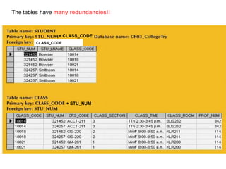


The document discusses entity relationship modeling and describes its objectives as illustrating relationships between entities, incorporating relationships into database design, and describing how ER components affect design and implementation. It explains that ER modeling is a top-down conceptual database design process that describes data, relationships, and constraints. The output is a conceptual data model and data dictionary. It details how to gather information, define entities and attributes, identify different types of relationships and their cardinalities, and convert many-to-many relationships into one-to-many relationships using composite or bridge entities. The document also provides guidelines for evaluating ER models based on accuracy, non-redundancy, and other principles.