The Entity-Relationship model is used for database design and includes several phases:
1) Requirement analysis involves understanding the data to be stored, applications needed, and common operations.
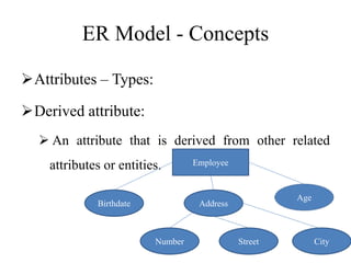
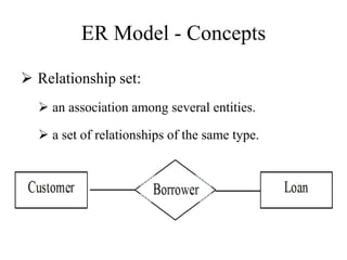
2) Conceptual design builds the ER model to describe data simply matching user requirements.
3) Logical design converts the ER model into a relational database schema.
4) Physical design addresses indexing, clustering, and security access rules.