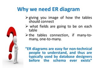
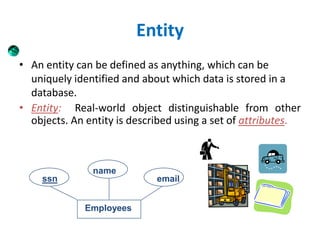
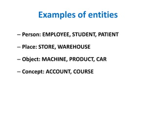
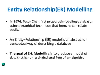
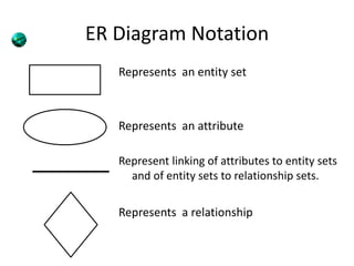
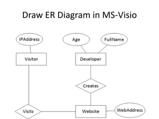
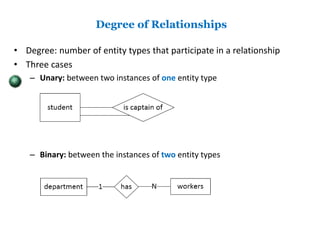
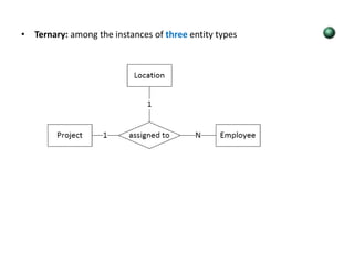
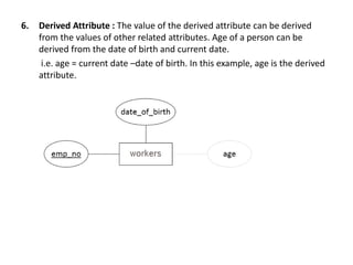
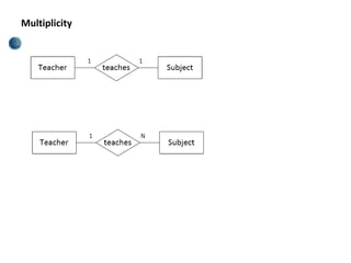
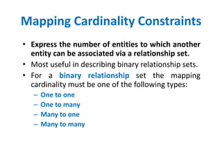
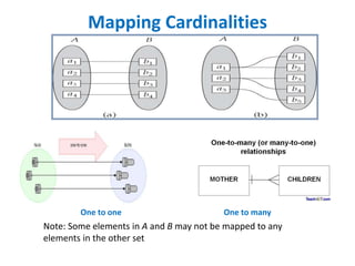
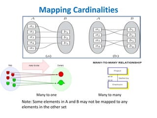
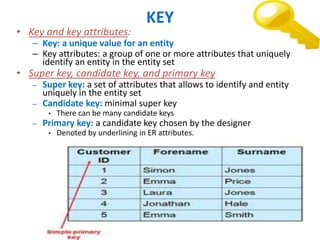
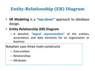
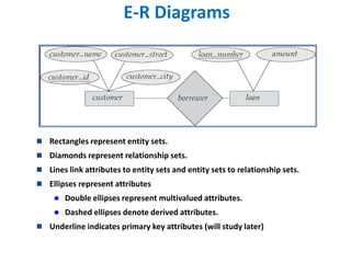
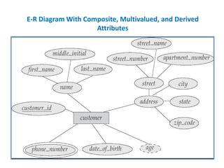
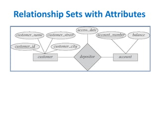
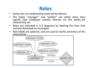
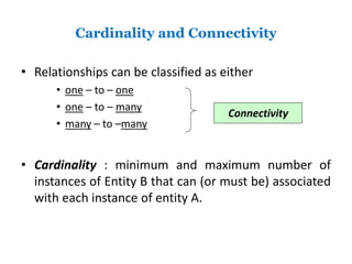
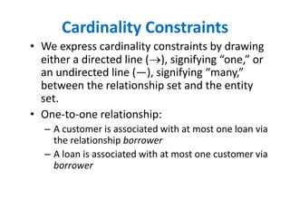
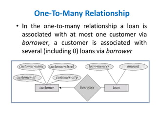
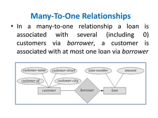
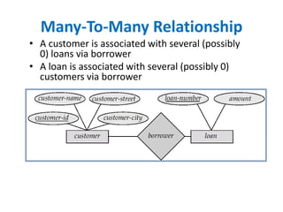
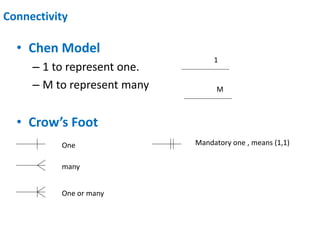
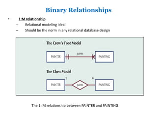
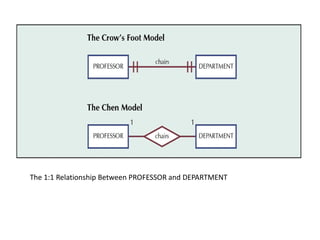
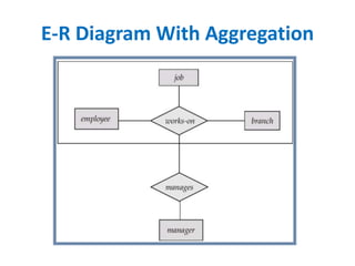
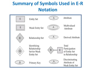
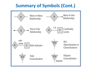
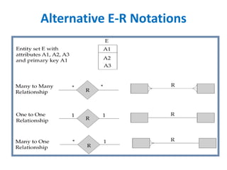
.
Enes BOLFİDAN
Ahmet Fahri KILIÇ
diagram
Topics
• Design Process
• Modeling
• Constraints
• E-R Diagram
• Design Issues
• Weak Entity Sets
• Extended E-R Features
DATA
unorganized
form
ex: student’s
score
Information
processed, structured and
organized data
ex: class average which can be
calculated from data.
TABLE
A table is a collection (rows) of data
on a single related topic.
Difference between table and
database
Table Database
A table is an object inside a
database
A database has tables of data,
a table is a collection (rows) of data
on a single related topic.
A database can have 10 or
thousands of tables
Ex: employee table
Contains only employees detail. But
it not contains inventory detail.
But DB is a collection of Employee
table as well as inventory table.
Sample Table
Sample Database DB is a
collection
related
tables
Why we need ER diagram
giving you image of how the tables
should connect
 what fields are going to be on each
table
the tables connection, if many-to-
many, one-to-many.
“ER diagrams are easy for non-technical
people to understand, and thus are
typically used by database designers
before the schema ever exists”
Entity
• An entity can be defined as anything, which can be
uniquely identified and about which data is stored in a
database.
• Entity: Real-world object distinguishable from other
objects. An entity is described using a set of attributes.
Employees
ssn
name
email
Examples of entities
– Person: EMPLOYEE, STUDENT, PATIENT
– Place: STORE, WAREHOUSE
– Object: MACHINE, PRODUCT, CAR
– Concept: ACCOUNT, COURSE
Entity Relationship(ER) Modelling
• In 1976, Peter Chen first proposed modeling databases
using a graphical technique that humans can relate
easily.
• An Entity–Relationship (ER) model is an abstract or
conceptual way of describing a database
• The goal of E-R Modelling is to produce a model of
data that is non-technical and free of ambiguities
Entity set
• Entity Set: A collection of similar entities.
E.g., all employees.
– All entities in an entity set have the same set of
attributes.
Person, place, object, event or
concept about which data is to
be maintained
named property or
characteristic of an
entity
Association between
the instances of one
or more entity types
EntityName Verb Phrase AttributeName
Example
RELATIONSHIP
• Relationship: Association among two or
more entities. e.g., rose works in Pharmacy
department.
• Relationship Set: Collection of similar
relationships.
• Same entity set could participate in different
relationship sets, or in different “roles” in same set.
Relationship Example
 Associations between instances of one or more entity types that is of
interest
 Buying is the relationship between Vendor and Customer.
Author Book
Relationship name:
writes
An author writes one or more books
A book can be written by one or more authors.
ER Diagram Notation
Represents an entity set
Represents an attribute
Represent linking of attributes to entity sets
and of entity sets to relationship sets.
Represents a relationship
Draw ER Diagram in MS-Visio
Degree of Relationships
• Degree: number of entity types that participate in a relationship
• Three cases
– Unary: between two instances of one entity type
– Binary: between the instances of two entity types
• Ternary: among the instances of three entity types
Attributes
• Example of entity types and associated attributes:
STUDENT: Student_ID, Student_Name, Home_Address, Phone_Number,
Major
Attribute types
1.Single-valued attribute
2.Multi-valued attribute
3.Simple Attribute
4.Composite Attribute
5.Key Attribute
6.Derived Attribute
1. Single-valued attribute : Attribute that holds a single value for an
occurrence of an entity type. E.g. age, first_name, last_name, full_name,
etc.
2 Multi-valued attribute :Attribute where there might be more than one
value for a given occurrence of an entity type.
Full Name
Age
Phone
number
Student
3. Simple Attribute: It is composed of a single component e.g. age,
first_name, last_name, etc. But full_name is not simple attribute.
Because it is composed of first_name and last_name.
4. Composite Attribute: It is composed of more than one component.
5. Key Attribute:
• Primary Key is a key attribute.
• At most one attribute in each entity
6. Derived Attribute : The value of the derived attribute can be derived
from the values of other related attributes. Age of a person can be
derived from the date of birth and current date.
i.e. age = current date –date of birth. In this example, age is the derived
attribute.
Multiplicity
Mapping Cardinality Constraints
• Express the number of entities to which another
entity can be associated via a relationship set.
• Most useful in describing binary relationship sets.
• For a binary relationship set the mapping
cardinality must be one of the following types:
– One to one
– One to many
– Many to one
– Many to many
Mapping Cardinalities
One to one One to many
Note: Some elements in A and B may not be mapped to any
elements in the other set
Mapping Cardinalities
Many to one Many to many
Note: Some elements in A and B may not be mapped to any
elements in the other set
KEY
• Key and key attributes:
– Key: a unique value for an entity
– Key attributes: a group of one or more attributes that uniquely
identify an entity in the entity set
• Super key, candidate key, and primary key
– Super key: a set of attributes that allows to identify and entity
uniquely in the entity set
– Candidate key: minimal super key
• There can be many candidate keys
– Primary key: a candidate key chosen by the designer
• Denoted by underlining in ER attributes.
Key Constraints
• Consider Works_In: An employee can work in many
departments; a dept can have many employees.
• In contrast, each dept has at most one manager,
according to the key constraint on Manages.
Weak Entity Sets
• An entity set that does not have a primary key is
referred to as a weak entity set.
• The existence of a weak entity set depends on
the existence of a identifying entity set
– it must relate to the identifying entity set
via a total, one-to-many relationship set
from the identifying to the weak entity set
– Identifying relationship depicted using a
double diamond
• In a relational database, a Weak Entity is an entity that cannot be
uniquely identified by its attributes alone; therefore, it must use
a foreign key in conjunction with its attributes to create a primary
key. The foreign key is typically a primary key of an entity it is
related to.
• Strong entity and Weak entity : Weak entity is an entity that
depends on another entity. Weak entity doesn't have key attribute
of their own.
Entity-Relationship (ER) Diagram
• ER Modeling is a “top-down” approach to database
design.
• Entity Relationship (ER) Diagram
– A detailed, “logical representation” of the entities,
associations and data elements for an organization or
business
Notation uses three main constructs
– Data entities
– Relationships
– Attributes
E-R Diagrams
 Rectangles represent entity sets.
 Diamonds represent relationship sets.
 Lines link attributes to entity sets and entity sets to relationship sets.
 Ellipses represent attributes
 Double ellipses represent multivalued attributes.
 Dashed ellipses denote derived attributes.
 Underline indicates primary key attributes (will study later)
E-R Diagram With Composite, Multivalued, and Derived
Attributes
Relationship Sets with Attributes
Roles
• Entity sets of a relationship need not be distinct
• The labels “manager” and “worker” are called roles; they
specify how employee entities interact via the works_for
relationship set.
• Roles are indicated in E-R diagrams by labeling the lines that
connect diamonds to rectangles.
• Role labels are optional, and are used to clarify semantics of the
relationship
Cardinality and Connectivity
• Relationships can be classified as either
• one – to – one
• one – to – many
• many – to –many
• Cardinality : minimum and maximum number of
instances of Entity B that can (or must be) associated
with each instance of entity A.
Connectivity
Cardinality Constraints
• We express cardinality constraints by drawing
either a directed line (), signifying “one,” or
an undirected line (—), signifying “many,”
between the relationship set and the entity
set.
• One-to-one relationship:
– A customer is associated with at most one loan via
the relationship borrower
– A loan is associated with at most one customer via
borrower
One-To-Many Relationship
• In the one-to-many relationship a loan is
associated with at most one customer via
borrower, a customer is associated with
several (including 0) loans via borrower
Many-To-One Relationships
• In a many-to-one relationship a loan is
associated with several (including 0)
customers via borrower, a customer is
associated with at most one loan via borrower
Many-To-Many Relationship
• A customer is associated with several (possibly
0) loans via borrower
• A loan is associated with several (possibly 0)
customers via borrower
Connectivity
• Chen Model
– 1 to represent one.
– M to represent many
• Crow’s Foot
many
One
One or many
1
M
Mandatory one , means (1,1)
Binary Relationships
• 1:M relationship
– Relational modeling ideal
– Should be the norm in any relational database design
The 1: M relationship between PAINTER and PAINTING
Binary Relationships
• 1:1 relationship
– Should be rare in any relational database design
– A single entity instance in one entity class is
related to a single entity instance in another
entity class
– Could indicate that two entities actually belong
in the same table
The 1:1 Relationship Between PROFESSOR and DEPARTMENT
Binary Relationships
• M:N relationships
– Must be avoided because they lead to data redundancies.
– Can be implemented by breaking it up to produce a set of 1:M
relationships
– Can avoid problems inherent to M:N relationship by creating a
composite entity or bridge entity
• This will be used to link the tables that were originally
related in a M:N relationship
• The composite entity structure includes-as foreign keys-at
least the primary keys of the tables that are to be linked.
The M:N Relationship Between STUDENT and CLASS
This CANNOT be implemented as shown next…..
Bowser
Smithson
Accounting 1 (ACCT-211)
Intro to Microcomputing (CIS-220)
Intro to Statistics (QM-261)
Changing the M:N relationship to TWO 1:M relationships
Extended E-R
• Specialization
• Generalization
• Aggregation
Specialization
• Top-down design process: we designate sub
groupings within an entity set that are
distinctive from other entities in the set.
• These sub groupings become lower-level entity
sets that have attributes or participate in
relationships that do not apply to the higher-
level entity set.
• Depicted by a “triangle component labeled ISA”
• Attribute inheritance – a lower-level entity set
inherits all the attributes and relationship
participation of the higher-level entity set to
which it is linked.
Specialization Example
Generalization
• A bottom-up design process – combine a number of entity
sets that share the same features into a higher-level entity
set.
• Specialization and generalization are simple inversions of
each other; they are represented in an E-R diagram in the
same way.
• The terms specialization and generalization are used
interchangeably.
Specialization and Generalization
(Cont.)
• Can have multiple specializations of an entity
set based on different features.
• E.g. permanent_employee vs.
temporary_employee, in addition to officer vs.
secretary vs. teller
• Each particular employee would be
– a member of one of permanent_employee or
temporary_employee,
– and also a member of one of officer, secretary, or
teller
• The ISA relationship also referred to as
“superclass – subclass” relationship
Design Constraints on a
Specialization/Generalization
• Constraint on which entities can be members of a
given lower-level entity set.
– Condition-defined : evaluated by an explicit condition or
predicate.
– User-defined : database user assigns
• Constraint on whether or not entities may belong to
more than one lower-level entity set within a single
generalization.
– Disjoint
• An entity can belong to only one lower-level entity set
• Noted in E-R diagram by writing disjoint next to the ISA triangle
– Overlapping
• an entity can belong to more than one lower-level entity set
Design Constraints on a
Specialization/Generalization (Contd.)
• Completeness constraint
– Total : an entity must belong to one of the
lower-level entity sets
– Partial : an entity need not belong to one of the
lower-level entity sets
Aggregation
 Consider the ternary relationship works-on, which we saw earlier
 Suppose we want to record managers for tasks performed by an
employee at a branch
Aggregation (Cont.)
• Relationship sets works_on and manages represent
overlapping information
– Every manages relationship corresponds to a works_on
relationship
– However, some works_on relationships may not correspond to
any manages relationships
• So we can’t discard the works_on relationship
• Eliminate this redundancy via aggregation
– Treat relationship as an abstract entity
– Allows relationships between relationships
– Abstraction of relationship into new entity
• Without introducing redundancy, the following diagram
represents:
– An employee works on a particular job at a particular branch
– An employee, branch, job combination may have an associated
manager
Aggregation (Cont.)
• Relationship sets works-on and manages
represent overlapping information
– Every manages relationship corresponds to a works-
on relationship
– However, some works-on relationships may not
correspond to any manages relationships  we
can’t discard the works-on relationship
• Redundancy problem  aggregation
E-R Diagram With Aggregation
Summary of Symbols Used in E-R
Notation
Summary of Symbols (Cont.)
Alternative E-R Notations
References
http://www.smartdraw.com/resources/tutorials/entity-relationship-
diagrams/
http://www.tutorialspoint.com/dbms/er_diagram_representation.htm
http://www-db.in.tum.de/~grust/teaching/ss06/DBfA/db1-04.pdf
http://s3.amazonaws.com/ppt-download/entity-relationship-diagram2
http://www.cse.unt.edu/~huangyan/5350/Slides/ER.ppt
http://en.wikipedia.org/wiki/Entity%E2%80%93relationship_model
http://databases.about.com/cs/specificproducts/g/er.htm

Entityrelationshipmodel

  • 1.
  • 2.
    Topics • Design Process •Modeling • Constraints • E-R Diagram • Design Issues • Weak Entity Sets • Extended E-R Features
  • 3.
  • 4.
    Information processed, structured and organizeddata ex: class average which can be calculated from data.
  • 5.
    TABLE A table isa collection (rows) of data on a single related topic.
  • 6.
    Difference between tableand database Table Database A table is an object inside a database A database has tables of data, a table is a collection (rows) of data on a single related topic. A database can have 10 or thousands of tables Ex: employee table Contains only employees detail. But it not contains inventory detail. But DB is a collection of Employee table as well as inventory table.
  • 7.
  • 8.
    Sample Database DBis a collection related tables
  • 9.
    Why we needER diagram giving you image of how the tables should connect  what fields are going to be on each table the tables connection, if many-to- many, one-to-many. “ER diagrams are easy for non-technical people to understand, and thus are typically used by database designers before the schema ever exists”
  • 10.
    Entity • An entitycan be defined as anything, which can be uniquely identified and about which data is stored in a database. • Entity: Real-world object distinguishable from other objects. An entity is described using a set of attributes. Employees ssn name email
  • 11.
    Examples of entities –Person: EMPLOYEE, STUDENT, PATIENT – Place: STORE, WAREHOUSE – Object: MACHINE, PRODUCT, CAR – Concept: ACCOUNT, COURSE
  • 12.
    Entity Relationship(ER) Modelling •In 1976, Peter Chen first proposed modeling databases using a graphical technique that humans can relate easily. • An Entity–Relationship (ER) model is an abstract or conceptual way of describing a database • The goal of E-R Modelling is to produce a model of data that is non-technical and free of ambiguities
  • 13.
    Entity set • EntitySet: A collection of similar entities. E.g., all employees. – All entities in an entity set have the same set of attributes.
  • 14.
    Person, place, object,event or concept about which data is to be maintained named property or characteristic of an entity Association between the instances of one or more entity types EntityName Verb Phrase AttributeName Example
  • 15.
    RELATIONSHIP • Relationship: Associationamong two or more entities. e.g., rose works in Pharmacy department. • Relationship Set: Collection of similar relationships. • Same entity set could participate in different relationship sets, or in different “roles” in same set.
  • 16.
    Relationship Example  Associationsbetween instances of one or more entity types that is of interest  Buying is the relationship between Vendor and Customer. Author Book Relationship name: writes An author writes one or more books A book can be written by one or more authors.
  • 17.
    ER Diagram Notation Representsan entity set Represents an attribute Represent linking of attributes to entity sets and of entity sets to relationship sets. Represents a relationship
  • 18.
    Draw ER Diagramin MS-Visio
  • 19.
    Degree of Relationships •Degree: number of entity types that participate in a relationship • Three cases – Unary: between two instances of one entity type – Binary: between the instances of two entity types
  • 20.
    • Ternary: amongthe instances of three entity types
  • 21.
    Attributes • Example ofentity types and associated attributes: STUDENT: Student_ID, Student_Name, Home_Address, Phone_Number, Major
  • 22.
    Attribute types 1.Single-valued attribute 2.Multi-valuedattribute 3.Simple Attribute 4.Composite Attribute 5.Key Attribute 6.Derived Attribute
  • 23.
    1. Single-valued attribute: Attribute that holds a single value for an occurrence of an entity type. E.g. age, first_name, last_name, full_name, etc. 2 Multi-valued attribute :Attribute where there might be more than one value for a given occurrence of an entity type. Full Name Age Phone number Student
  • 24.
    3. Simple Attribute:It is composed of a single component e.g. age, first_name, last_name, etc. But full_name is not simple attribute. Because it is composed of first_name and last_name. 4. Composite Attribute: It is composed of more than one component. 5. Key Attribute: • Primary Key is a key attribute. • At most one attribute in each entity
  • 25.
    6. Derived Attribute: The value of the derived attribute can be derived from the values of other related attributes. Age of a person can be derived from the date of birth and current date. i.e. age = current date –date of birth. In this example, age is the derived attribute.
  • 26.
  • 27.
    Mapping Cardinality Constraints •Express the number of entities to which another entity can be associated via a relationship set. • Most useful in describing binary relationship sets. • For a binary relationship set the mapping cardinality must be one of the following types: – One to one – One to many – Many to one – Many to many
  • 28.
    Mapping Cardinalities One toone One to many Note: Some elements in A and B may not be mapped to any elements in the other set
  • 29.
    Mapping Cardinalities Many toone Many to many Note: Some elements in A and B may not be mapped to any elements in the other set
  • 30.
    KEY • Key andkey attributes: – Key: a unique value for an entity – Key attributes: a group of one or more attributes that uniquely identify an entity in the entity set • Super key, candidate key, and primary key – Super key: a set of attributes that allows to identify and entity uniquely in the entity set – Candidate key: minimal super key • There can be many candidate keys – Primary key: a candidate key chosen by the designer • Denoted by underlining in ER attributes.
  • 31.
    Key Constraints • ConsiderWorks_In: An employee can work in many departments; a dept can have many employees. • In contrast, each dept has at most one manager, according to the key constraint on Manages.
  • 32.
    Weak Entity Sets •An entity set that does not have a primary key is referred to as a weak entity set. • The existence of a weak entity set depends on the existence of a identifying entity set – it must relate to the identifying entity set via a total, one-to-many relationship set from the identifying to the weak entity set – Identifying relationship depicted using a double diamond
  • 33.
    • In arelational database, a Weak Entity is an entity that cannot be uniquely identified by its attributes alone; therefore, it must use a foreign key in conjunction with its attributes to create a primary key. The foreign key is typically a primary key of an entity it is related to. • Strong entity and Weak entity : Weak entity is an entity that depends on another entity. Weak entity doesn't have key attribute of their own.
  • 34.
    Entity-Relationship (ER) Diagram •ER Modeling is a “top-down” approach to database design. • Entity Relationship (ER) Diagram – A detailed, “logical representation” of the entities, associations and data elements for an organization or business Notation uses three main constructs – Data entities – Relationships – Attributes
  • 35.
    E-R Diagrams  Rectanglesrepresent entity sets.  Diamonds represent relationship sets.  Lines link attributes to entity sets and entity sets to relationship sets.  Ellipses represent attributes  Double ellipses represent multivalued attributes.  Dashed ellipses denote derived attributes.  Underline indicates primary key attributes (will study later)
  • 36.
    E-R Diagram WithComposite, Multivalued, and Derived Attributes
  • 37.
  • 38.
    Roles • Entity setsof a relationship need not be distinct • The labels “manager” and “worker” are called roles; they specify how employee entities interact via the works_for relationship set. • Roles are indicated in E-R diagrams by labeling the lines that connect diamonds to rectangles. • Role labels are optional, and are used to clarify semantics of the relationship
  • 39.
    Cardinality and Connectivity •Relationships can be classified as either • one – to – one • one – to – many • many – to –many • Cardinality : minimum and maximum number of instances of Entity B that can (or must be) associated with each instance of entity A. Connectivity
  • 40.
    Cardinality Constraints • Weexpress cardinality constraints by drawing either a directed line (), signifying “one,” or an undirected line (—), signifying “many,” between the relationship set and the entity set. • One-to-one relationship: – A customer is associated with at most one loan via the relationship borrower – A loan is associated with at most one customer via borrower
  • 41.
    One-To-Many Relationship • Inthe one-to-many relationship a loan is associated with at most one customer via borrower, a customer is associated with several (including 0) loans via borrower
  • 42.
    Many-To-One Relationships • Ina many-to-one relationship a loan is associated with several (including 0) customers via borrower, a customer is associated with at most one loan via borrower
  • 43.
    Many-To-Many Relationship • Acustomer is associated with several (possibly 0) loans via borrower • A loan is associated with several (possibly 0) customers via borrower
  • 44.
    Connectivity • Chen Model –1 to represent one. – M to represent many • Crow’s Foot many One One or many 1 M Mandatory one , means (1,1)
  • 45.
    Binary Relationships • 1:Mrelationship – Relational modeling ideal – Should be the norm in any relational database design The 1: M relationship between PAINTER and PAINTING
  • 46.
    Binary Relationships • 1:1relationship – Should be rare in any relational database design – A single entity instance in one entity class is related to a single entity instance in another entity class – Could indicate that two entities actually belong in the same table
  • 47.
    The 1:1 RelationshipBetween PROFESSOR and DEPARTMENT
  • 48.
    Binary Relationships • M:Nrelationships – Must be avoided because they lead to data redundancies. – Can be implemented by breaking it up to produce a set of 1:M relationships – Can avoid problems inherent to M:N relationship by creating a composite entity or bridge entity • This will be used to link the tables that were originally related in a M:N relationship • The composite entity structure includes-as foreign keys-at least the primary keys of the tables that are to be linked.
  • 49.
    The M:N RelationshipBetween STUDENT and CLASS This CANNOT be implemented as shown next….. Bowser Smithson Accounting 1 (ACCT-211) Intro to Microcomputing (CIS-220) Intro to Statistics (QM-261)
  • 50.
    Changing the M:Nrelationship to TWO 1:M relationships
  • 51.
    Extended E-R • Specialization •Generalization • Aggregation
  • 52.
    Specialization • Top-down designprocess: we designate sub groupings within an entity set that are distinctive from other entities in the set. • These sub groupings become lower-level entity sets that have attributes or participate in relationships that do not apply to the higher- level entity set. • Depicted by a “triangle component labeled ISA” • Attribute inheritance – a lower-level entity set inherits all the attributes and relationship participation of the higher-level entity set to which it is linked.
  • 53.
  • 54.
    Generalization • A bottom-updesign process – combine a number of entity sets that share the same features into a higher-level entity set. • Specialization and generalization are simple inversions of each other; they are represented in an E-R diagram in the same way. • The terms specialization and generalization are used interchangeably.
  • 55.
    Specialization and Generalization (Cont.) •Can have multiple specializations of an entity set based on different features. • E.g. permanent_employee vs. temporary_employee, in addition to officer vs. secretary vs. teller • Each particular employee would be – a member of one of permanent_employee or temporary_employee, – and also a member of one of officer, secretary, or teller • The ISA relationship also referred to as “superclass – subclass” relationship
  • 56.
    Design Constraints ona Specialization/Generalization • Constraint on which entities can be members of a given lower-level entity set. – Condition-defined : evaluated by an explicit condition or predicate. – User-defined : database user assigns • Constraint on whether or not entities may belong to more than one lower-level entity set within a single generalization. – Disjoint • An entity can belong to only one lower-level entity set • Noted in E-R diagram by writing disjoint next to the ISA triangle – Overlapping • an entity can belong to more than one lower-level entity set
  • 57.
    Design Constraints ona Specialization/Generalization (Contd.) • Completeness constraint – Total : an entity must belong to one of the lower-level entity sets – Partial : an entity need not belong to one of the lower-level entity sets
  • 58.
    Aggregation  Consider theternary relationship works-on, which we saw earlier  Suppose we want to record managers for tasks performed by an employee at a branch
  • 59.
    Aggregation (Cont.) • Relationshipsets works_on and manages represent overlapping information – Every manages relationship corresponds to a works_on relationship – However, some works_on relationships may not correspond to any manages relationships • So we can’t discard the works_on relationship • Eliminate this redundancy via aggregation – Treat relationship as an abstract entity – Allows relationships between relationships – Abstraction of relationship into new entity • Without introducing redundancy, the following diagram represents: – An employee works on a particular job at a particular branch – An employee, branch, job combination may have an associated manager
  • 60.
    Aggregation (Cont.) • Relationshipsets works-on and manages represent overlapping information – Every manages relationship corresponds to a works- on relationship – However, some works-on relationships may not correspond to any manages relationships  we can’t discard the works-on relationship • Redundancy problem  aggregation
  • 61.
    E-R Diagram WithAggregation
  • 62.
    Summary of SymbolsUsed in E-R Notation
  • 63.
  • 64.
  • 65.