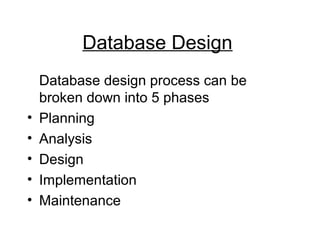
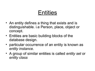
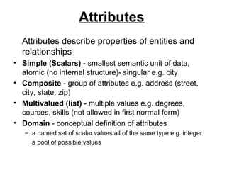
Database Design
Database design process can be
broken down into 5 phases
• Planning
• Analysis
• Design
• Implementation
• Maintenance
Planning Phase
In planning phase the overall Database
structure is defined. Therefore;
• The purpose of the database is determined
– What information will be used in the Database
– How information is to be used
– What question will be Answered
• Feasibility studies are conducted.
• Requirements gathering
Analysis phase
Databases can be analyzed on different models
• Conceptual-model
– High-level description of facts
– Not system specific
• Logical model
– Organization of data with some implementation information
• Physical model
– Actual storage of information (clustering, partitioning,
indexing etc.)
Conceptual model
• Provide a framework for developing a
database structure.
• Three database components (entities,
attributes and relationship) are
described in detail.
Entities
• An entity defines a thing that exists and is
distinguishable. i.e Person, place, object or
concept.
• Entities are basic building blocks of the
database design.
• particular occurrence of an entity is known as
entity instance.
• A group of similar entities is called entity set or
entity class
Attributes
Attributes describe properties of entities and
relationships
• Simple (Scalars) - smallest semantic unit of data,
atomic (no internal structure)- singular e.g. city
• Composite - group of attributes e.g. address (street,
city, state, zip)
• Multivalued (list) - multiple values e.g. degrees,
courses, skills (not allowed in first normal form)
• Domain - conceptual definition of attributes
– a named set of scalar values all of the same type e.g. integer
a pool of possible values
Relationships
A relationship is a connection between entity classes.
For example, a relationship between PERSONS and
AUTOMOBILES could be an "OWNS" relationship.
That is to say, people own automobiles.
• The degree of a relationship indicates the number of entities
involved.
• The cardinality of a relationship indicates the number of
instances in entity class E1 that can or must be associated
with instances in entity class E2
Types of Relationship
Based on cardinality of a relationship, we have 3
types: -
• One-One Relationship - For each entity in one class there is at most one
associated entity in the other class. For example, for each husband there is
at most one current legal wife (in this country at least). A wife has at most
one current legal husband.
• Many-One Relationships - One entity in class E2 is associated with zero or
more entities in class E1, but each entity in E1 is associated with at most
one entity in E2. For example, a woman may have many children but a
child has only one birth mother.
• Many-Many Relationships - There are no restrictions on how many entities
in either class are associated with a single entity in the other. An example
of a many-to-many relationship would be students taking classes. Each
student takes many classes. Each class has many students.
Logical model
• After validating your conceptual mode,
you can generate a logical model
– Entity Classes are modeled as tables
– Attributes are modeled as fields
– Each instance of an entity is called a record
– Domain are modeled as Data types
– Primary keys for each table
– Foreign keys for relationship
Physical –model
• How data will be stored and accessed in a
computer system.
• Where data will be stored
• Estimate the amount of disk space that will be
required by the database.
• How data will be distributed within an
organization or disks
• type of indexes to be used (for efficient
retrieval and manipulation).
Design Phase
Determine how best to represent the
information system that was identified in the
previous phase
Mapping Logical Model and physical model
into reality.
– Database Management system (DBMS) to
be used.
– User Views (input forms, output reports)
– Security Mechanisms etc.
Implementation phase
Actual implementation of the database and
associated programming.
• Database is analyzed for possible errors
• Tables are created with few records for
sample to see if the desired results are
achieved
• Fine adjustments as needed
Entity Relationship Model
• Conceptual data model that views the real
world as entities and relationships.
• A basic component of the model is the
Entity-Relationship diagrams (ERDs),
• (ERDs) provides a convenient method for
visualizing the interrelationships among
entities in a given application
The utility of the ER model is:
• It maps well to the relational database
model..
• It is simple and easy to understand with
a minimum of training.
• the model can be used as a design plan
by the database developer to implement
a data model in specific database
management software.
Basic Elements in E-R Modeling
The basic elements in ER modal are
• entities
• attributes and
• Relationships.
Entities
• Data object about which information is to be
collected.
• Some specific examples of entities are
EMPLOYEE, PROJECT, INVOICE.
• An entity occurrence (also called an instance)
is an individual occurrence of an entity.
• Entity set: a collection of similar
entities (employees, projects,
departments)
Attributes
• describe the entity of which they are associated.
• A particular instance of an attribute is a value.
• Attributes can be classified as identifiers or
descriptors.
• Identifiers, more commonly called keys,
uniquely identify an instance of an entity.
• A descriptor describes a non-unique
characteristic of an entity instance.
Relationships
• Represents an association between two or
more entities. An example of a relationship
would be:
employees are assigned to projects
projects have subtasks
departments manage one or more projects
• Relationships are classified in terms of
– degree,
– connectivity,
– cardinality,
– and existence.
Classifying Relationships
Degree of a Relationship
• number of entities associated with the relationship.
 A UNARY RELATIONSHIP exists when an
association exists within a single entity
 A BINARY RELATIONSHIP exists when two
entities(participants) are in the relationship.
 A TERNARY RELATIONSHIP exists when three
entities (participants) are in the relationship.
Classifying Relationships
The connectivity
– describes the mapping of associated entity
instances in the relationship.
– The values of connectivity are "one" or "many".
– The basic types of connectivity for relations are:
one-to-one, one-to-many, and many-to-many.
The cardinality
– actual number of related occurrences for each of
the two entities.
Classifying Relationships
Existence
• denotes whether the existence of an entity instance is
dependent upon the existence of another, related,
entity instance.
• Defined as either mandatory or optional.
– For mandatory existence an instance of an entity must
always occur. "every project must be managed by a single
department".
– For optional existence the instance of the entity is not
required or may occur
ER Notation
• There is no universal standard for
representing data objects in ER
diagrams.
• Number of Notation styles is used
today, among the more common are
information Engineering, Bachman,
Chen and Martin.
ER Notation
Martin Style.
• Entities are represented by labeled rectangles. The label is the
name of the entity. Entity names should be singular nouns.
• Relationships are represented by a solid line connecting two
entities. The name of the relationship is written above the line.
Relationship names should be verbs.
• Attributes, when included, are listed inside the entity
rectangle. Identifier Attributes are underlined. Attribute names
should be singular nouns.
• Cardinality of many is represented by a line ending in a crow's
foot. If the crow's foot is omitted, the cardinality is one.
•
Existence is represented by placing a circle or a perpendicular
bar on the line. Placing a bar line next to the entity shows
mandatory existence. Placing a circle next to the entity shows
optional existence.
Martin Style.
ER Notation
Chen Style
• Rectangles represent ENTITY CLASSES
• Circles represent ATTRIBUTES
• Diamonds represent RELATIONSHIPS
• Lines - lines connect entities to relationships. Lines are
also used to connect attributes to entities.
• Underline - Key attributes of entities are underlined.
• Number Notations represents cardinality.
• The name of the entity (class) or attribute or relationship is
usually placed inside the symbol used for that object.
(Sometimes, the name is placed adjacent.)
•
Chen Style
Refining The Entity-Relationship Diagram
This section discusses four basic rules for
modeling relationships
1. Entities Must Participate In
Relationships
– Entities cannot be modeled unrelated to
any other entity.
– The exception to this rule is a database
with a single table.
Refining The Entity-Relationship Diagram
2. Resolve Many-To-Many Relationships
– Many-to-many relationships cannot be used in
the data model because they cannot be
represented by the relational model.
– must be resolved early in the modeling process.
– replace the relationship with an association
entity and then relate the two original entities to
the association entity
This strategy is demonstrated below Figure below: -
Here
Employees may be assigned to many projects.
Each project must have assigned to it more than one employee.
Refining The Entity-Relationship Diagram
3. Transform Complex Relationships into Binary
Relationships
• Complex relationships are classified as ternary, an association
among three entities, or n-ary, an association among more than
three, where n is the number of entities involved.
• cannot be directly implemented in the relational model.
• so they should be resolved early in the modeling process.
• The strategy for resolving complex relationships is similar to
resolving many-to-many relationships.
• Replace the complex relationship with an association entity and
then relate the two original entities to the association entity
Here is an example
Employees can use different skills on any one or more projects.
Each project uses many employees with various skills.
Refining The Entity-Relationship Diagram
4. Eliminate redundant relationships
– A redundant relationship is a relationship
between two entities that is equivalent in
meaning to another relationship between
those same two entities.
For example,
Figure A shows a redundant relationship between DEPARTMENT and
WORKSTATION.
This relationship provides the same information as the relationships DEPARTMENT
has EMPLOYEES and EMPLOYEEs assigned WORKSTATION.
Figure B shows the solution which is to remove the redundant relationship
DEPARTMENT assigned WORKSTATIONS.
Tips for Effective ER Diagrams
• Make sure that each entity only appears once per
diagram.
• Name every entity, relationship, and attribute on your
diagram.
• Examine relationships between entities closely. Are
they necessary? Are their any relationships missing?
Eliminate any redundant relationships. Don't connect
relationships to each other.
• Use colors to highlight important portions of your
diagram
Normalization
• Normalization is the process of refining a database
design to produce table schemes in normal form.
• A normal form refers to a class of relational schemas that
obey some set of rules.
• Schemas that obey the rules are said to be in the normal
form.
• Non–normal form is where data may recur repetitively.
• Normalization is aiming at minimizing redundancy in
database
Classifying normal forms
• There are six commonly recognized
normal forms, with the inspired names:
– First normal form (or 1NF)
– Second normal form (or 2NF)
– Third normal form (or 3NF)
– Boyce-Codd normal form (or BCNF)
– Fourth normal form (or 4NF)
– Fifth normal form (or 5NF)
• We will consider the first three of these
normal forms
First normal form (or 1NF)
A relation is in First Normal Form (1NF) if
every attribute value is indivisible (atomic)
and every column is unique.
• First normal form (1NF) sets the very basic
rules for an organized database:
– Eliminate duplicative columns from the same table.
– Create separate tables for each group of related data
and identify each row with a unique column or set of
columns (the primary key).
Second normal form (or 2NF)
A relation is in Second Normal Form (2NF) if it is in
1NF and if all of its attributes are dependent on the
whole key (i.e. none of the non-key attributes are
related only to a part of the key).
• Second normal form (2NF) further addresses
the concept of removing duplicative data:
– Remove subsets of data that apply to multiple rows
of a table and place them in separate tables.
•     Create relationships between these new tables and
their predecessors through the use of foreign keys.
Third normal form (or 3NF)
A relation is in Third Normal Form (3NF) if it is in 2NF
and there are no transitive dependencies (i.e. none of
the non-key attributes are dependent upon another
attribute which in turn is dependent on the relation
key).
• Third normal form (3NF) goes one large step
further:
Remove columns that are not dependent upon the
primary key.
Fourth normal form (or 4NF)
• A relation is in 4NF if it has no
multi-valued dependencies.

Database design

  • 1.
    Database Design Database designprocess can be broken down into 5 phases • Planning • Analysis • Design • Implementation • Maintenance
  • 2.
    Planning Phase In planningphase the overall Database structure is defined. Therefore; • The purpose of the database is determined – What information will be used in the Database – How information is to be used – What question will be Answered • Feasibility studies are conducted. • Requirements gathering
  • 3.
    Analysis phase Databases canbe analyzed on different models • Conceptual-model – High-level description of facts – Not system specific • Logical model – Organization of data with some implementation information • Physical model – Actual storage of information (clustering, partitioning, indexing etc.)
  • 4.
    Conceptual model • Providea framework for developing a database structure. • Three database components (entities, attributes and relationship) are described in detail.
  • 5.
    Entities • An entitydefines a thing that exists and is distinguishable. i.e Person, place, object or concept. • Entities are basic building blocks of the database design. • particular occurrence of an entity is known as entity instance. • A group of similar entities is called entity set or entity class
  • 6.
    Attributes Attributes describe propertiesof entities and relationships • Simple (Scalars) - smallest semantic unit of data, atomic (no internal structure)- singular e.g. city • Composite - group of attributes e.g. address (street, city, state, zip) • Multivalued (list) - multiple values e.g. degrees, courses, skills (not allowed in first normal form) • Domain - conceptual definition of attributes – a named set of scalar values all of the same type e.g. integer a pool of possible values
  • 7.
    Relationships A relationship isa connection between entity classes. For example, a relationship between PERSONS and AUTOMOBILES could be an "OWNS" relationship. That is to say, people own automobiles. • The degree of a relationship indicates the number of entities involved. • The cardinality of a relationship indicates the number of instances in entity class E1 that can or must be associated with instances in entity class E2
  • 8.
    Types of Relationship Basedon cardinality of a relationship, we have 3 types: - • One-One Relationship - For each entity in one class there is at most one associated entity in the other class. For example, for each husband there is at most one current legal wife (in this country at least). A wife has at most one current legal husband. • Many-One Relationships - One entity in class E2 is associated with zero or more entities in class E1, but each entity in E1 is associated with at most one entity in E2. For example, a woman may have many children but a child has only one birth mother. • Many-Many Relationships - There are no restrictions on how many entities in either class are associated with a single entity in the other. An example of a many-to-many relationship would be students taking classes. Each student takes many classes. Each class has many students.
  • 9.
    Logical model • Aftervalidating your conceptual mode, you can generate a logical model – Entity Classes are modeled as tables – Attributes are modeled as fields – Each instance of an entity is called a record – Domain are modeled as Data types – Primary keys for each table – Foreign keys for relationship
  • 10.
    Physical –model • Howdata will be stored and accessed in a computer system. • Where data will be stored • Estimate the amount of disk space that will be required by the database. • How data will be distributed within an organization or disks • type of indexes to be used (for efficient retrieval and manipulation).
  • 11.
    Design Phase Determine howbest to represent the information system that was identified in the previous phase Mapping Logical Model and physical model into reality. – Database Management system (DBMS) to be used. – User Views (input forms, output reports) – Security Mechanisms etc.
  • 12.
    Implementation phase Actual implementationof the database and associated programming. • Database is analyzed for possible errors • Tables are created with few records for sample to see if the desired results are achieved • Fine adjustments as needed
  • 13.
    Entity Relationship Model •Conceptual data model that views the real world as entities and relationships. • A basic component of the model is the Entity-Relationship diagrams (ERDs), • (ERDs) provides a convenient method for visualizing the interrelationships among entities in a given application
  • 14.
    The utility ofthe ER model is: • It maps well to the relational database model.. • It is simple and easy to understand with a minimum of training. • the model can be used as a design plan by the database developer to implement a data model in specific database management software.
  • 15.
    Basic Elements inE-R Modeling The basic elements in ER modal are • entities • attributes and • Relationships.
  • 16.
    Entities • Data objectabout which information is to be collected. • Some specific examples of entities are EMPLOYEE, PROJECT, INVOICE. • An entity occurrence (also called an instance) is an individual occurrence of an entity. • Entity set: a collection of similar entities (employees, projects, departments)
  • 17.
    Attributes • describe theentity of which they are associated. • A particular instance of an attribute is a value. • Attributes can be classified as identifiers or descriptors. • Identifiers, more commonly called keys, uniquely identify an instance of an entity. • A descriptor describes a non-unique characteristic of an entity instance.
  • 18.
    Relationships • Represents anassociation between two or more entities. An example of a relationship would be: employees are assigned to projects projects have subtasks departments manage one or more projects • Relationships are classified in terms of – degree, – connectivity, – cardinality, – and existence.
  • 19.
    Classifying Relationships Degree ofa Relationship • number of entities associated with the relationship.  A UNARY RELATIONSHIP exists when an association exists within a single entity  A BINARY RELATIONSHIP exists when two entities(participants) are in the relationship.  A TERNARY RELATIONSHIP exists when three entities (participants) are in the relationship.
  • 20.
    Classifying Relationships The connectivity –describes the mapping of associated entity instances in the relationship. – The values of connectivity are "one" or "many". – The basic types of connectivity for relations are: one-to-one, one-to-many, and many-to-many. The cardinality – actual number of related occurrences for each of the two entities.
  • 21.
    Classifying Relationships Existence • denoteswhether the existence of an entity instance is dependent upon the existence of another, related, entity instance. • Defined as either mandatory or optional. – For mandatory existence an instance of an entity must always occur. "every project must be managed by a single department". – For optional existence the instance of the entity is not required or may occur
  • 22.
    ER Notation • Thereis no universal standard for representing data objects in ER diagrams. • Number of Notation styles is used today, among the more common are information Engineering, Bachman, Chen and Martin.
  • 23.
    ER Notation Martin Style. •Entities are represented by labeled rectangles. The label is the name of the entity. Entity names should be singular nouns. • Relationships are represented by a solid line connecting two entities. The name of the relationship is written above the line. Relationship names should be verbs. • Attributes, when included, are listed inside the entity rectangle. Identifier Attributes are underlined. Attribute names should be singular nouns. • Cardinality of many is represented by a line ending in a crow's foot. If the crow's foot is omitted, the cardinality is one. • Existence is represented by placing a circle or a perpendicular bar on the line. Placing a bar line next to the entity shows mandatory existence. Placing a circle next to the entity shows optional existence.
  • 24.
  • 25.
    ER Notation Chen Style •Rectangles represent ENTITY CLASSES • Circles represent ATTRIBUTES • Diamonds represent RELATIONSHIPS • Lines - lines connect entities to relationships. Lines are also used to connect attributes to entities. • Underline - Key attributes of entities are underlined. • Number Notations represents cardinality. • The name of the entity (class) or attribute or relationship is usually placed inside the symbol used for that object. (Sometimes, the name is placed adjacent.) •
  • 26.
  • 27.
    Refining The Entity-RelationshipDiagram This section discusses four basic rules for modeling relationships 1. Entities Must Participate In Relationships – Entities cannot be modeled unrelated to any other entity. – The exception to this rule is a database with a single table.
  • 28.
    Refining The Entity-RelationshipDiagram 2. Resolve Many-To-Many Relationships – Many-to-many relationships cannot be used in the data model because they cannot be represented by the relational model. – must be resolved early in the modeling process. – replace the relationship with an association entity and then relate the two original entities to the association entity
  • 29.
    This strategy isdemonstrated below Figure below: - Here Employees may be assigned to many projects. Each project must have assigned to it more than one employee.
  • 30.
    Refining The Entity-RelationshipDiagram 3. Transform Complex Relationships into Binary Relationships • Complex relationships are classified as ternary, an association among three entities, or n-ary, an association among more than three, where n is the number of entities involved. • cannot be directly implemented in the relational model. • so they should be resolved early in the modeling process. • The strategy for resolving complex relationships is similar to resolving many-to-many relationships. • Replace the complex relationship with an association entity and then relate the two original entities to the association entity
  • 31.
    Here is anexample Employees can use different skills on any one or more projects. Each project uses many employees with various skills.
  • 32.
    Refining The Entity-RelationshipDiagram 4. Eliminate redundant relationships – A redundant relationship is a relationship between two entities that is equivalent in meaning to another relationship between those same two entities.
  • 33.
    For example, Figure Ashows a redundant relationship between DEPARTMENT and WORKSTATION. This relationship provides the same information as the relationships DEPARTMENT has EMPLOYEES and EMPLOYEEs assigned WORKSTATION. Figure B shows the solution which is to remove the redundant relationship DEPARTMENT assigned WORKSTATIONS.
  • 34.
    Tips for EffectiveER Diagrams • Make sure that each entity only appears once per diagram. • Name every entity, relationship, and attribute on your diagram. • Examine relationships between entities closely. Are they necessary? Are their any relationships missing? Eliminate any redundant relationships. Don't connect relationships to each other. • Use colors to highlight important portions of your diagram
  • 35.
    Normalization • Normalization isthe process of refining a database design to produce table schemes in normal form. • A normal form refers to a class of relational schemas that obey some set of rules. • Schemas that obey the rules are said to be in the normal form. • Non–normal form is where data may recur repetitively. • Normalization is aiming at minimizing redundancy in database
  • 36.
    Classifying normal forms •There are six commonly recognized normal forms, with the inspired names: – First normal form (or 1NF) – Second normal form (or 2NF) – Third normal form (or 3NF) – Boyce-Codd normal form (or BCNF) – Fourth normal form (or 4NF) – Fifth normal form (or 5NF) • We will consider the first three of these normal forms
  • 37.
    First normal form(or 1NF) A relation is in First Normal Form (1NF) if every attribute value is indivisible (atomic) and every column is unique. • First normal form (1NF) sets the very basic rules for an organized database: – Eliminate duplicative columns from the same table. – Create separate tables for each group of related data and identify each row with a unique column or set of columns (the primary key).
  • 38.
    Second normal form(or 2NF) A relation is in Second Normal Form (2NF) if it is in 1NF and if all of its attributes are dependent on the whole key (i.e. none of the non-key attributes are related only to a part of the key). • Second normal form (2NF) further addresses the concept of removing duplicative data: – Remove subsets of data that apply to multiple rows of a table and place them in separate tables. •     Create relationships between these new tables and their predecessors through the use of foreign keys.
  • 39.
    Third normal form(or 3NF) A relation is in Third Normal Form (3NF) if it is in 2NF and there are no transitive dependencies (i.e. none of the non-key attributes are dependent upon another attribute which in turn is dependent on the relation key). • Third normal form (3NF) goes one large step further: Remove columns that are not dependent upon the primary key.
  • 40.
    Fourth normal form(or 4NF) • A relation is in 4NF if it has no multi-valued dependencies.