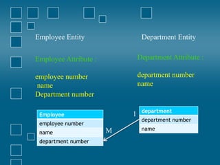
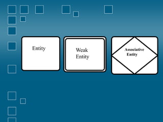
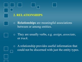
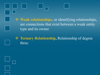
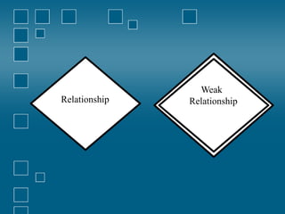
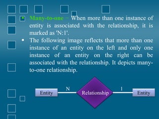
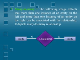
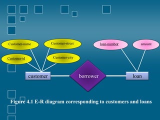
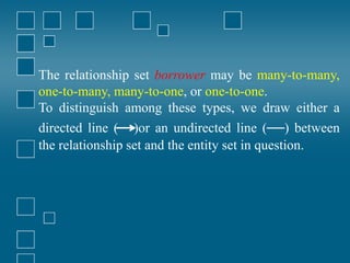
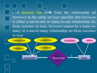
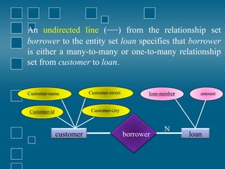
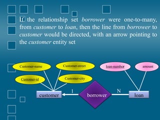
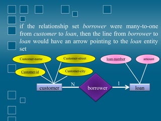
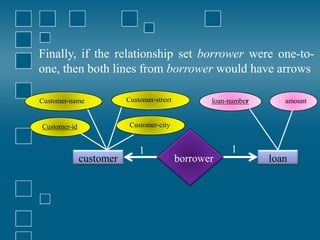
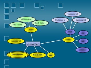
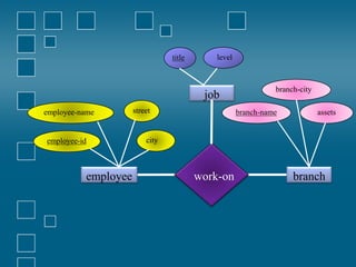
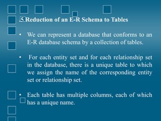
Chapter 4
Entity-Relationship Diagram
(ERD)
1. Introduction.
An entity-relationship diagram (ERD) is :
 a data modeling technique that
graphically illustrates an information
system’s entities and the relationships
between those entities.
 a conceptual and representational model
of data used to represent the entity
framework infrastructure.
Steps involved in creating an ERD include:
1. Identifying and defining the entities.
2. Determining all interactions between the entities.
3. Analyzing the nature of interactions/determining
the cardinality of the relationships.
4. Creating the ERD.
 crucial to creating a good database design.
 used as a high-level logical data model, which is
useful in developing a conceptual design for
databases.
Entity
 An entity is a real-world item or concept
that exists on its own.
 Entities are equivalent to database tables
in a relational database, with each row of
the table representing an instance of that
entity.
Attribute
 An attribute of an entity is a particular property that
describes the entity.
Relationship
 A relationship is the association that describes the
interaction between entities.
Cardinality
 in the context of ERD, is the number of instances of
one entity that can, or must, be associated with each
instance of another entity. In general, there may be
one-to-one, one-to-many, or many-to-many
relationships.
Employee
employee number
name
department number
department
department number
name
1
M
Employee Entity Department Entity
Employee Attribute :
employee number
name
Department number
Department Attribute :
department number
name
2 Components of E-R Diagram
 Entity relational diagram (ER Diagram) is
used to represent the requirement analysis at the
conceptual design stage.
 the database is designed from the ERD
or ERD is converted to the database.
 Each entity in the ERD corresponds to a table in
the database.
 The attributes of any an entity correspond to field
of a table.
 The ERD is converted to the database.
The elements of an ERD are:
1. ENTITIES
 Entities are objects or concepts that represent
important data.
 They are typically nouns (customer, supervisor, location,
or promotion).
 Strong entities exist independently from other
entity types. They always possess one or more
attributes that uniquely distinguish each
occurrence of the entity.
 Weak entities depend on some other entity type.
They don't possess unique attributes (also known
as a primary key) and have no meaning in the
diagram without depending on another entity.
This other entity is known as the owner.
 Associative entities are entities that associate the
instances of one or more entity types. They also
contain attributes that are unique to the
relationship between those entity instances.
Entity Weak
Entity
Associative
Entity
2. RELATIONSHIPS
o Relationships are meaningful associations
between or among entities.
o They are usually verbs, e.g. assign, associate,
or track.
o A relationship provides useful information that
could not be discerned with just the entity types.
 Weak relationships, or identifying relationships,
are connections that exist between a weak entity
type and its owner.
 Ternary Relationship, Relationship of degree
three.
Relationship
Weak
Relationship
3. ATTRIBUTES
 Attributes are characteristics of either an
entity, a many-to-many relationship, or a
one-to-one relationship.
Attribute
Multivalued attributes are those that are
capable of taking on more than one value.
.
Multivalued
Attributes
 Derived attributes are attributes whose value can
be calculated from related attribute values.
Derived
Attributes
 Composite attributes are represented by ellipses
that are connected with an ellipse. they are further
divided in a tree like structure. Every node is then
connected to its attribute
Attribute
Attribute
composite
Attribute
 Key attribute represents the main characteristic of
an Entity. It is used to represent Primary key.
Ellipse with underlying lines represent Key
Attribute.
Key
Attribute
3. Binary Relationship and Cardinality
 Binary relationship :A relationship where two
entities are participating.
 Cardinality is the number of instance of an entity
from a relation that can be associated with the
relation.
 One-to-one − When only one instance of an
entity is associated with the relationship, it is
marked as '1:1'. The following image reflects that
only one instance of each entity should be
associated with the relationship. It depicts one-to-
one relationship.
The following image reflects that only one instance
of each entity should be associated with the
relationship. It depicts one-to-one relationship.
Entity
Relationship
Entity
1
1
 One-to-many − When more than one instance of
an entity is associated with a relationship, it is
marked as '1:N'.
The following image reflects that only one
instance of entity on the left and more than one
instance of an entity on the right can be associated
with the relationship. It depicts one-to-many
relationship.
Entity
Relationship
Entity
N
1
 Many-to-one − When more than one instance of
entity is associated with the relationship, it is
marked as 'N:1'.
 The following image reflects that more than one
instance of an entity on the left and only one
instance of an entity on the right can be
associated with the relationship. It depicts many-
to-one relationship.
Entity
Relationship
Entity
1
N
 Many-to-many − The following image reflects
that more than one instance of an entity on the
left and more than one instance of an entity on
the right can be associated with the relationship.
It depicts many-to-many relationship.
Entity
Relationship
Entity
N
N
Customer-id
Customer-name
loan
borrower
customer
amount
loan-number
Customer-street
Customer-city
Figure 4.1 E-R diagram corresponding to customers and loans
The relationship set borrower may be many-to-many,
one-to-many, many-to-one, or one-to-one.
To distinguish among these types, we draw either a
directed line (→)or an undirected line (—) between
the relationship set and the entity set in question.
• A directed line (→) from the relationship set
borrower to the entity set loan specifies that borrower
is either a one-to-one or many-to-one relationship set,
from customer to loan, borrower cannot be a many-to-
many or a one-to-many relationship set from customer
to loan
Customer-id
Customer-name
loan
borrower
customer
amount
loan-number
Customer-street
Customer-city
1
An undirected line (—) from the relationship set
borrower to the entity set loan specifies that borrower
is either a many-to-many or one-to-many relationship
set from customer to loan.
Customer-id
Customer-name
loan
borrower
customer
amount
loan-number
Customer-street
Customer-city
N
If the relationship set borrower were one-to-many,
from customer to loan, then the line from borrower to
customer would be directed, with an arrow pointing to
the customer entity set
borrower
customer
Customer-id
Customer-name Customer-street
Customer-city
loan
amount
loan-number
1 N
if the relationship set borrower were many-to-one
from customer to loan, then the line from borrower to
loan would have an arrow pointing to the loan entity
set
borrower
customer
Customer-id
Customer-name Customer-street
Customer-city
loan
amount
loan-number
N 1
Finally, if the relationship set borrower were one-to-
one, then both lines from borrower would have arrows
borrower
customer
Customer-id
Customer-name Customer-street
Customer-city
loan
amount
loan-number
1 1
customer
Customer-id
name
street
Customer-id
First- name
middle-name
Last- name
date-of-birth age
Phone-number
Customer-id
address
city
state
zip-code
Customer-id
work-on
employee
employee-id
employee-name street
city
branch
assets
branch-name
job
branch-city
title level
.5 Reduction of an E-R Schema to Tables
• We can represent a database that conforms to an
E-R database schema by a collection of tables.
• For each entity set and for each relationship set
in the database, there is a unique table to which
we assign the name of the corresponding entity
set or relationship set.
• Each table has multiple columns, each of which
has a unique name.
Both the E-R model and the relational-database
model are:
 abstract, logical representations of real-world
enterprises.
Because the two models employ similar design
principles, we can convert an E-R design into a
relational design.
Converting a database representation from an E-R
diagram to a table format is the way we arrive at a
relational-database design from an E-R diagram.
Although important differences exist between a
relation and a table, informally, a relation can be
considered to be a table of values.
The constraints specified in an E-R diagram, such as
primary keys and cardinality constraints, are mapped
to constraints on the tables generated from the E-R
diagram.
Example :
There is an entity:
customer-schema=(customer-id,name,address,city-state-ZIP,discount)
1.Transforming an entity to a relation – E/R Diagram.
2.Transforming an entity to a relation – relational .
customer
Customer-id
name
Address
City-state-zip
Discount
Discount
City –State-Zip
Address
Name
Customer –ID
5%
Austin,TX2888
123 Oak St.
Contemporary Designs
1273
3%
Bloomington ,IN5482
18 Hoosier Dr.
Casual Comer
6390

Entity relationship Models from Chapter 4

  • 1.
  • 2.
  • 3.
    An entity-relationship diagram(ERD) is :  a data modeling technique that graphically illustrates an information system’s entities and the relationships between those entities.  a conceptual and representational model of data used to represent the entity framework infrastructure.
  • 4.
    Steps involved increating an ERD include: 1. Identifying and defining the entities. 2. Determining all interactions between the entities. 3. Analyzing the nature of interactions/determining the cardinality of the relationships. 4. Creating the ERD.
  • 5.
     crucial tocreating a good database design.  used as a high-level logical data model, which is useful in developing a conceptual design for databases.
  • 6.
    Entity  An entityis a real-world item or concept that exists on its own.  Entities are equivalent to database tables in a relational database, with each row of the table representing an instance of that entity.
  • 7.
    Attribute  An attributeof an entity is a particular property that describes the entity. Relationship  A relationship is the association that describes the interaction between entities. Cardinality  in the context of ERD, is the number of instances of one entity that can, or must, be associated with each instance of another entity. In general, there may be one-to-one, one-to-many, or many-to-many relationships.
  • 8.
    Employee employee number name department number department departmentnumber name 1 M Employee Entity Department Entity Employee Attribute : employee number name Department number Department Attribute : department number name
  • 9.
    2 Components ofE-R Diagram  Entity relational diagram (ER Diagram) is used to represent the requirement analysis at the conceptual design stage.  the database is designed from the ERD or ERD is converted to the database.  Each entity in the ERD corresponds to a table in the database.  The attributes of any an entity correspond to field of a table.  The ERD is converted to the database.
  • 10.
    The elements ofan ERD are: 1. ENTITIES  Entities are objects or concepts that represent important data.  They are typically nouns (customer, supervisor, location, or promotion).
  • 11.
     Strong entitiesexist independently from other entity types. They always possess one or more attributes that uniquely distinguish each occurrence of the entity.  Weak entities depend on some other entity type. They don't possess unique attributes (also known as a primary key) and have no meaning in the diagram without depending on another entity. This other entity is known as the owner.  Associative entities are entities that associate the instances of one or more entity types. They also contain attributes that are unique to the relationship between those entity instances.
  • 13.
  • 14.
    2. RELATIONSHIPS o Relationshipsare meaningful associations between or among entities. o They are usually verbs, e.g. assign, associate, or track. o A relationship provides useful information that could not be discerned with just the entity types.
  • 15.
     Weak relationships,or identifying relationships, are connections that exist between a weak entity type and its owner.  Ternary Relationship, Relationship of degree three.
  • 16.
  • 17.
    3. ATTRIBUTES  Attributesare characteristics of either an entity, a many-to-many relationship, or a one-to-one relationship. Attribute
  • 18.
    Multivalued attributes arethose that are capable of taking on more than one value. . Multivalued Attributes
  • 19.
     Derived attributesare attributes whose value can be calculated from related attribute values. Derived Attributes
  • 20.
     Composite attributesare represented by ellipses that are connected with an ellipse. they are further divided in a tree like structure. Every node is then connected to its attribute Attribute Attribute composite Attribute
  • 21.
     Key attributerepresents the main characteristic of an Entity. It is used to represent Primary key. Ellipse with underlying lines represent Key Attribute. Key Attribute
  • 22.
    3. Binary Relationshipand Cardinality  Binary relationship :A relationship where two entities are participating.  Cardinality is the number of instance of an entity from a relation that can be associated with the relation.  One-to-one − When only one instance of an entity is associated with the relationship, it is marked as '1:1'. The following image reflects that only one instance of each entity should be associated with the relationship. It depicts one-to- one relationship.
  • 23.
    The following imagereflects that only one instance of each entity should be associated with the relationship. It depicts one-to-one relationship. Entity Relationship Entity 1 1
  • 24.
     One-to-many −When more than one instance of an entity is associated with a relationship, it is marked as '1:N'. The following image reflects that only one instance of entity on the left and more than one instance of an entity on the right can be associated with the relationship. It depicts one-to-many relationship. Entity Relationship Entity N 1
  • 25.
     Many-to-one −When more than one instance of entity is associated with the relationship, it is marked as 'N:1'.  The following image reflects that more than one instance of an entity on the left and only one instance of an entity on the right can be associated with the relationship. It depicts many- to-one relationship. Entity Relationship Entity 1 N
  • 26.
     Many-to-many −The following image reflects that more than one instance of an entity on the left and more than one instance of an entity on the right can be associated with the relationship. It depicts many-to-many relationship. Entity Relationship Entity N N
  • 27.
  • 28.
    The relationship setborrower may be many-to-many, one-to-many, many-to-one, or one-to-one. To distinguish among these types, we draw either a directed line (→)or an undirected line (—) between the relationship set and the entity set in question.
  • 29.
    • A directedline (→) from the relationship set borrower to the entity set loan specifies that borrower is either a one-to-one or many-to-one relationship set, from customer to loan, borrower cannot be a many-to- many or a one-to-many relationship set from customer to loan Customer-id Customer-name loan borrower customer amount loan-number Customer-street Customer-city 1
  • 30.
    An undirected line(—) from the relationship set borrower to the entity set loan specifies that borrower is either a many-to-many or one-to-many relationship set from customer to loan. Customer-id Customer-name loan borrower customer amount loan-number Customer-street Customer-city N
  • 31.
    If the relationshipset borrower were one-to-many, from customer to loan, then the line from borrower to customer would be directed, with an arrow pointing to the customer entity set borrower customer Customer-id Customer-name Customer-street Customer-city loan amount loan-number 1 N
  • 32.
    if the relationshipset borrower were many-to-one from customer to loan, then the line from borrower to loan would have an arrow pointing to the loan entity set borrower customer Customer-id Customer-name Customer-street Customer-city loan amount loan-number N 1
  • 33.
    Finally, if therelationship set borrower were one-to- one, then both lines from borrower would have arrows borrower customer Customer-id Customer-name Customer-street Customer-city loan amount loan-number 1 1
  • 34.
    customer Customer-id name street Customer-id First- name middle-name Last- name date-of-birthage Phone-number Customer-id address city state zip-code Customer-id
  • 35.
  • 36.
    .5 Reduction ofan E-R Schema to Tables • We can represent a database that conforms to an E-R database schema by a collection of tables. • For each entity set and for each relationship set in the database, there is a unique table to which we assign the name of the corresponding entity set or relationship set. • Each table has multiple columns, each of which has a unique name.
  • 37.
    Both the E-Rmodel and the relational-database model are:  abstract, logical representations of real-world enterprises. Because the two models employ similar design principles, we can convert an E-R design into a relational design. Converting a database representation from an E-R diagram to a table format is the way we arrive at a relational-database design from an E-R diagram.
  • 38.
    Although important differencesexist between a relation and a table, informally, a relation can be considered to be a table of values. The constraints specified in an E-R diagram, such as primary keys and cardinality constraints, are mapped to constraints on the tables generated from the E-R diagram.
  • 39.
    Example : There isan entity: customer-schema=(customer-id,name,address,city-state-ZIP,discount) 1.Transforming an entity to a relation – E/R Diagram. 2.Transforming an entity to a relation – relational .
  • 40.
    customer Customer-id name Address City-state-zip Discount Discount City –State-Zip Address Name Customer –ID 5% Austin,TX2888 123Oak St. Contemporary Designs 1273 3% Bloomington ,IN5482 18 Hoosier Dr. Casual Comer 6390