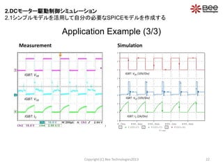
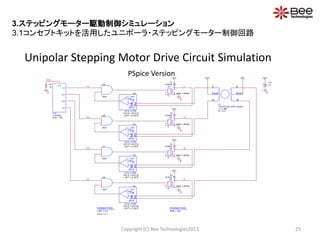
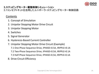
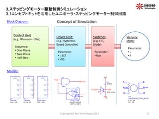
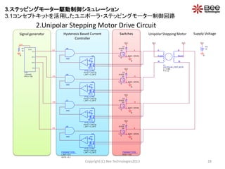
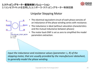
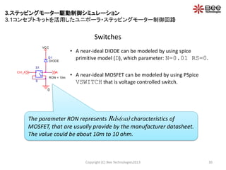
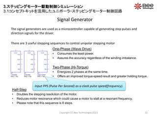
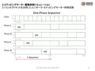
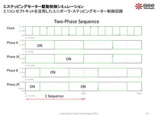
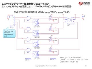
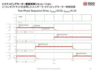
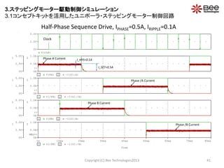
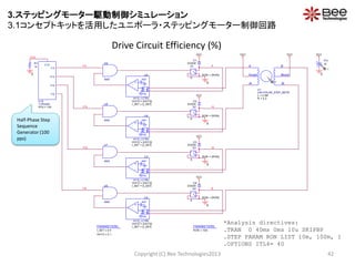
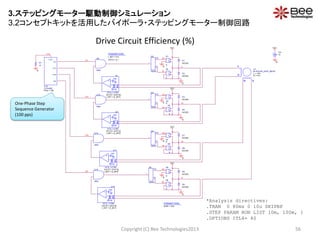
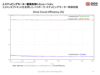
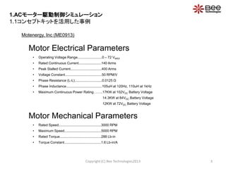
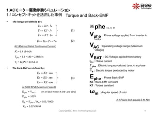
This document discusses simulations of motor drive control using SPICE. It describes AC motor drive control simulation using a concept kit and simple model. It also describes DC and stepping motor drive control simulations using simple models. It provides an introduction to motor drive control device modeling services and includes a Q&A section. Simulation examples are presented for an AC motor model showing current, back-EMF voltage, speed, torque, output power and efficiency characteristics under different load conditions. Parameters for DC motor models are also discussed.


![Parameters Settings
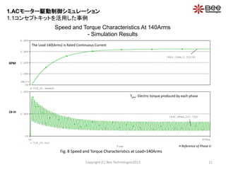
Copyright (C) Bee Technologies2013 7
LOAD : Load current each phase of motor [Arms]
– e.g. LL = 125Arms, 140Arms, or 400Arms
LL : Phase inductance [H]
– e.g. LL = 10mH, 100mH, or 1H
RLL : Phase resistance (Phase-to-phase) [Ω]
– e.g. RLL = 10mΩ, 100mΩ, or 1Ω
KE : Back-EMF constant [V/RPM]
– e.g. KE= 0.01, 0.05, or 0.1
KT : Torque constant [Lb-in/A]
– e.g. KT= 0.1, 0.5, or 1
1 Pound Inch equals 0.11 Nm
Model Parameters:
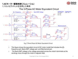
Fig. 4 Symbol of 3-Phase Induction Motor
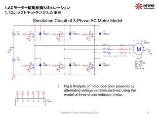
• From the 3-Phase Induction Motor specification, the model is characterized by setting parameters
LL, RLL, KE, KT and LOAD.
M N0
U1
ME0913
LL = 105U
LOAD = 140
KT = 1.6
KE = 0.02
RLL = 0.0125
1
2
3
4
1.ACモーター駆動制御シミュレーション
1.1コンセプトキットを活用した事例](https://image.slidesharecdn.com/spice-130423232950-phpapp01/85/Spice-7-320.jpg)
![Time
0.5s 1.0s
100*( (RMS(V(U,N0))*RMS(I(RU))) / (RMS(V(RU:1,N0))*RMS(I(RU))) )
0
50
100
(962.500m,81.941)
RMS(V(RU:1,N0))*RMS(I(RU))
0W
10KW
20KW
SEL>>
(960.616m,13.662K)
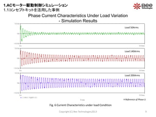
Power Output and Efficiency Characteristics At 140Arms
- Simulation Results
Copyright (C) Bee Technologies2013 12
Fig. 9 Power Output and Efficiency Characteristics at Load=140Arms
At Load=140Arms, Power Output ≈ 13.7 [KW]
At Load=140Arms, Efficiency ≈ 82 [%]
Watt
[%]
Reference of Phase U
1.ACモーター駆動制御シミュレーション
1.1コンセプトキットを活用した事例](https://image.slidesharecdn.com/spice-130423232950-phpapp01/85/Spice-12-320.jpg)
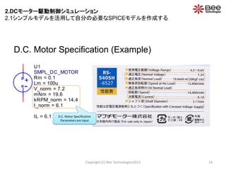
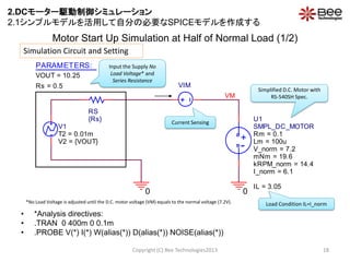
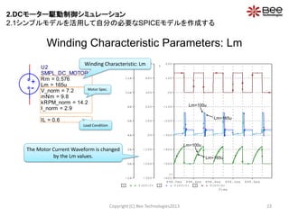
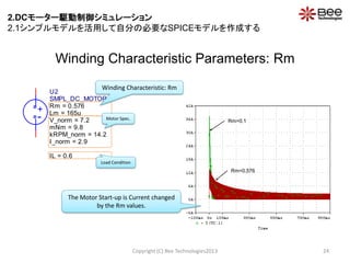
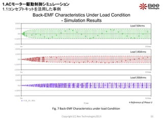
![Parameter Settings If there is no measurement data, the default value will be
used:
Rm: motor winding resistance []
Lm: motor winding inductance [H]
Data is given by D.C. motor spec-sheet:
V_norm: normal voltage [V]
mNm: normal load [mNm]
kRPM_norm: speed at normal load [kr/min]
I_norm: current at normal load [A]
Load Condition:
IL: load current [A]
Copyright (C) Bee Technologies2013 13
Model Parameters:
D.C. Motor model and Parameters with Default Value
-
+
U1
SMPL_DC_MOTOR
Rm = 0.1
Lm = 100u
I_norm = 6.1
mNm = 19.6
V_norm = 7.2
kRPM_norm = 14.4
IL = 6.1
2.DCモーター駆動制御シミュレーション
2.1シンプルモデルを活用して自分の必要なSPICEモデルを作成する](https://image.slidesharecdn.com/spice-130423232950-phpapp01/85/Spice-13-320.jpg)