Download to read offline
![2.7 Speed at No Load (Model)
• This figure shows the simulated speed at no load (16,400rpm). To monitor the speed
,trace “ I(U1.Vrpm) ” inside the model .SUBCKT.
Note: To show I(U1.Vrmp), select "Save Subcircuit Device Currents“ ( Tool > Control Panel > Save Default [tab] ).
All Rights Reserved Copyright (C) Bee Technologies Inc. 2011 7
Speed at No Load
=16,400 rpm.
Simulation
Normal Voltage
=7.2V.
Motor current
Time (s)](https://image.slidesharecdn.com/29nov2011dcmtdrvltspice-181009041752/75/The-Simulation-of-DC-Motor-Control-Circuit-7-2048.jpg)

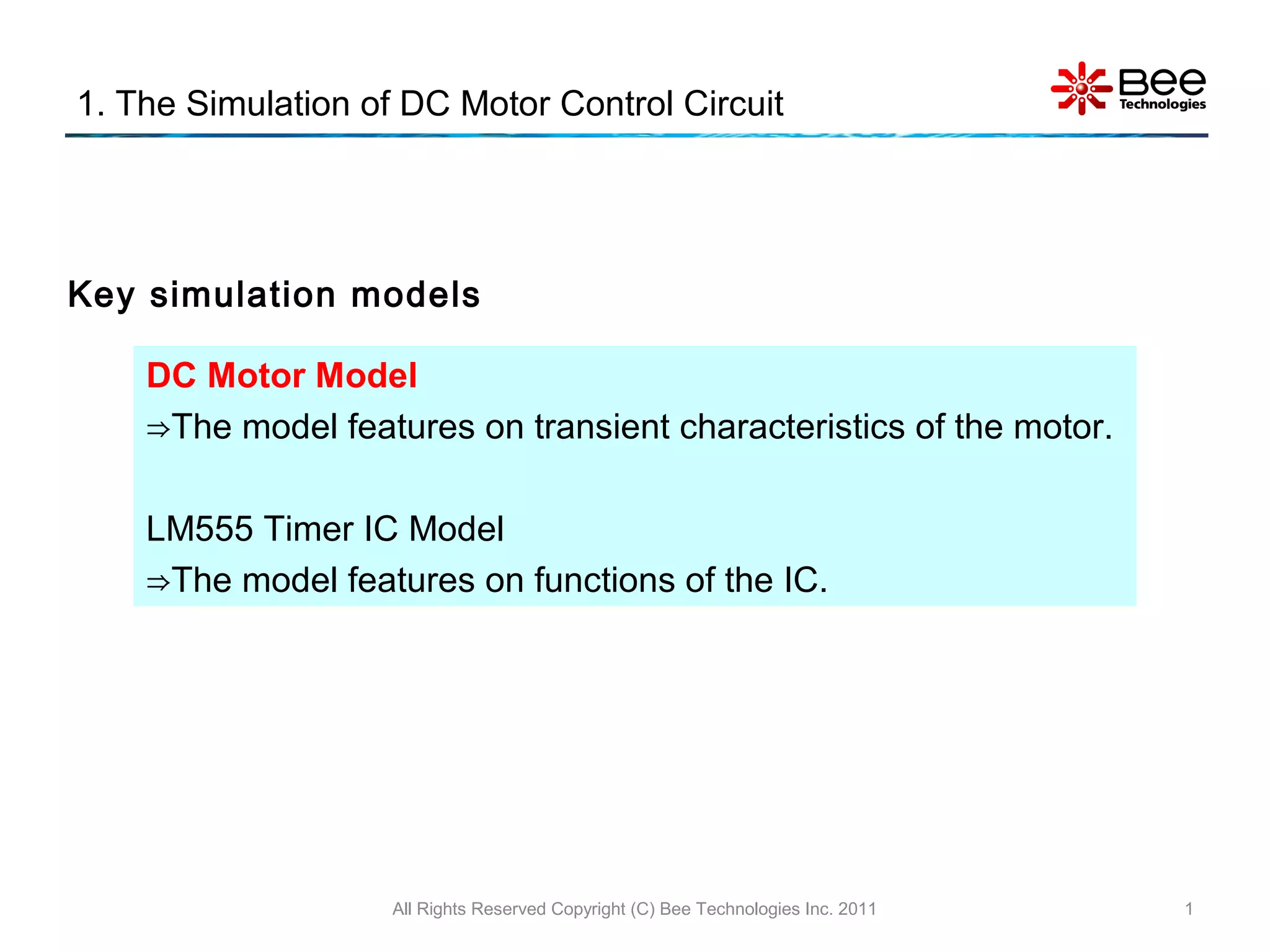
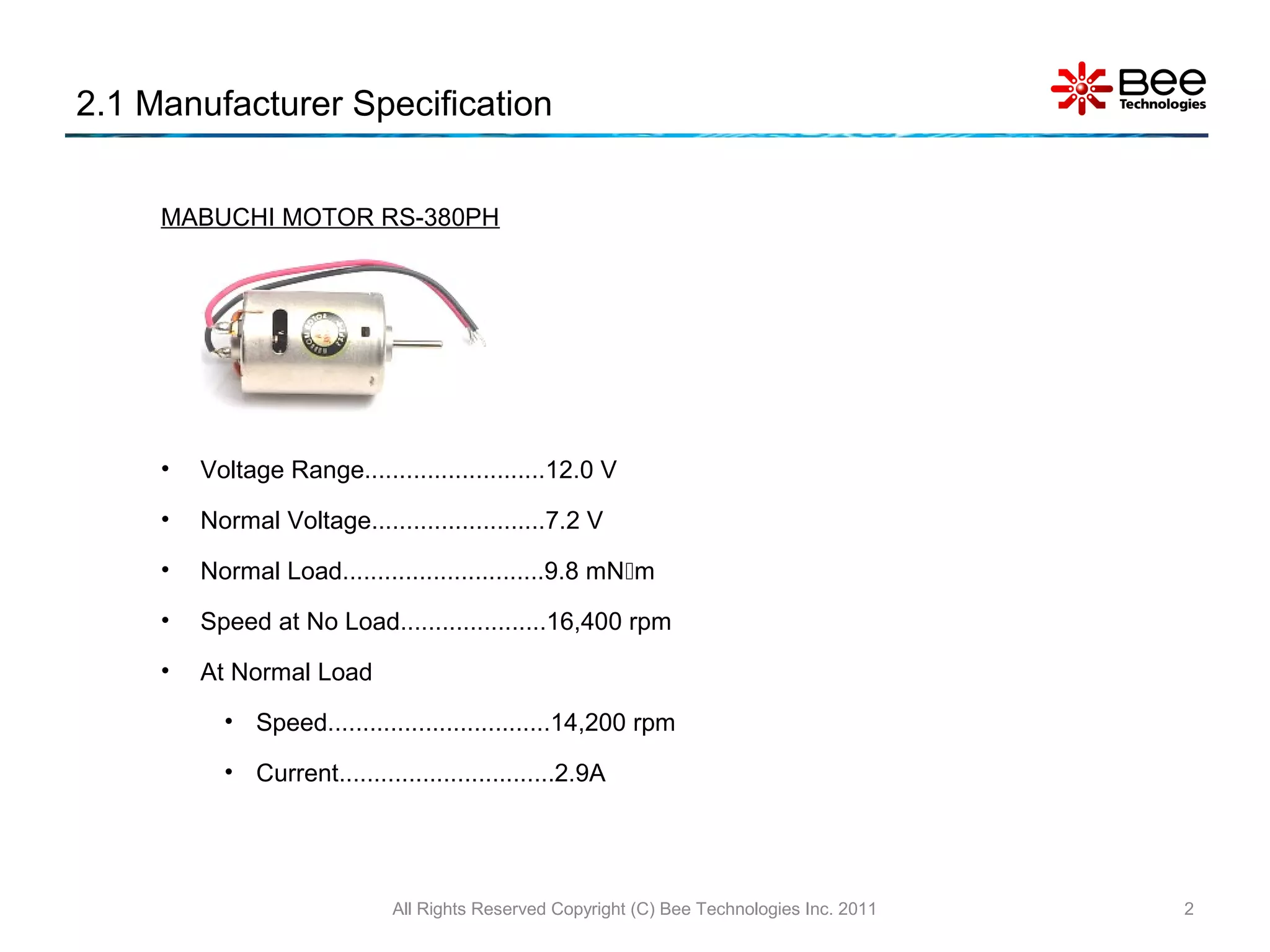
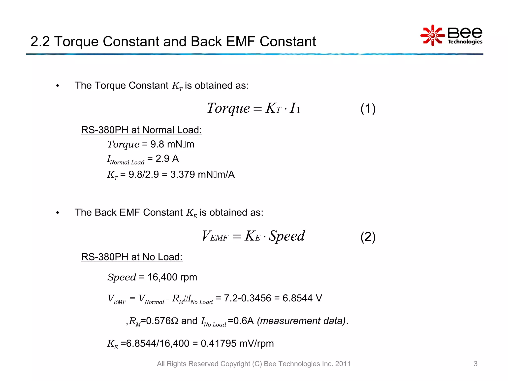
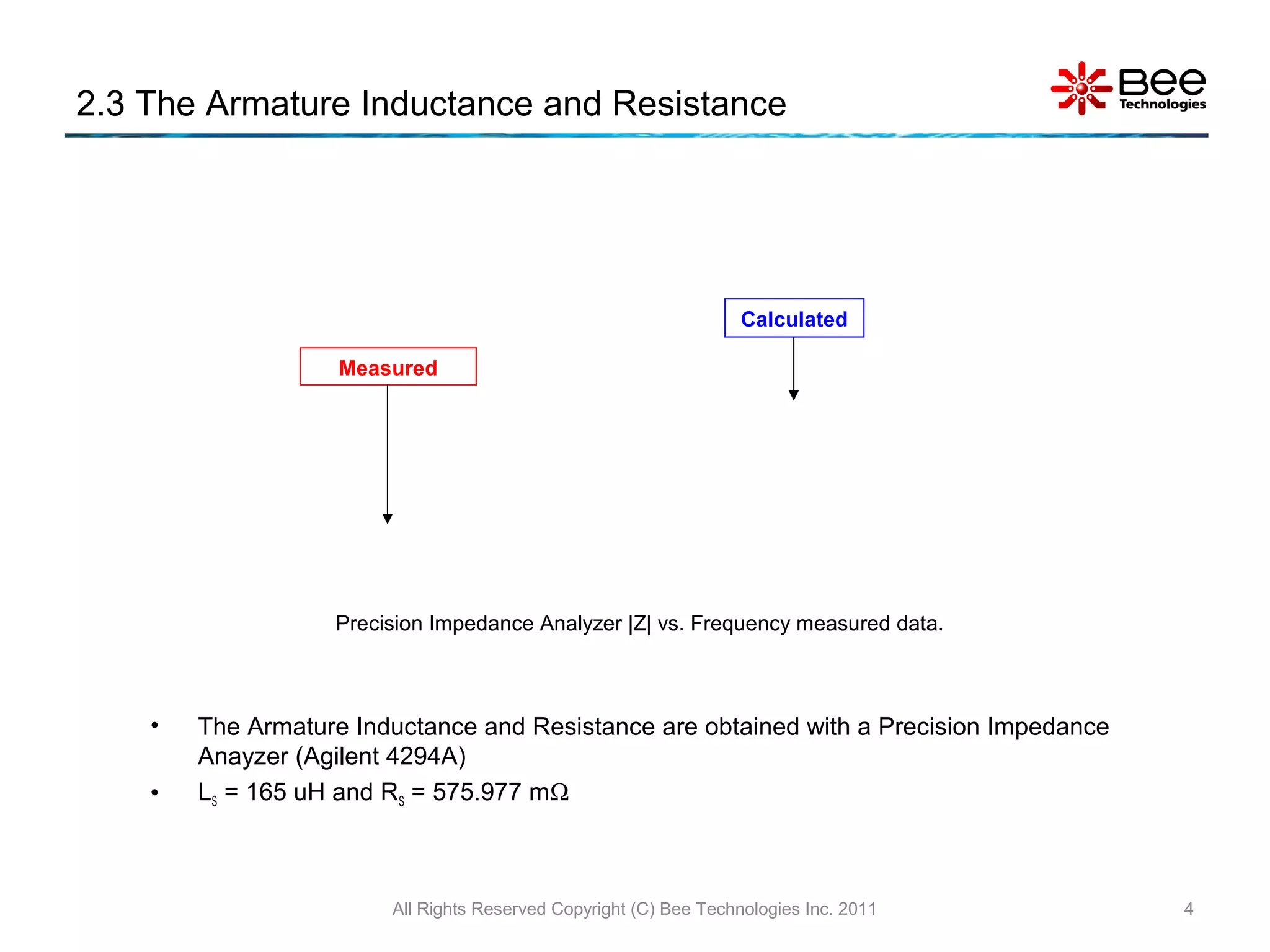
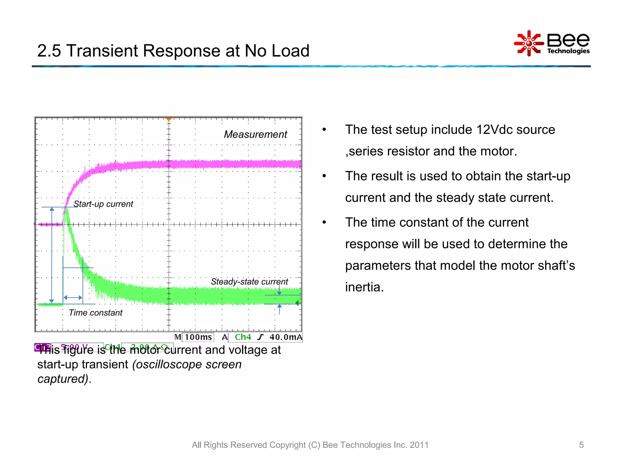
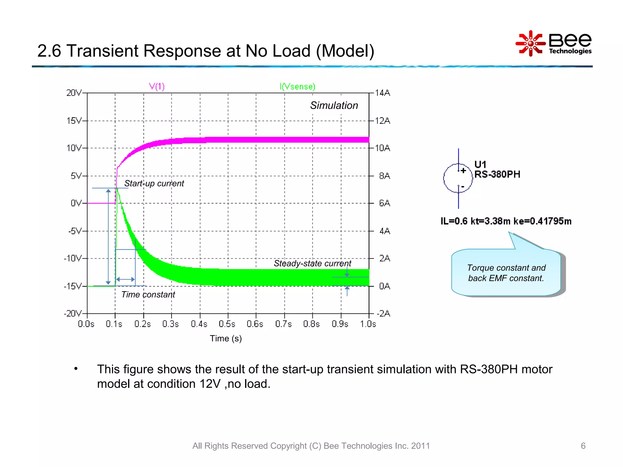
This document summarizes the simulation of a DC motor control circuit. It describes the DC motor and LM555 timer IC models. It then provides specifications for the Mabuchi RS-380PH motor and outlines how its torque constant, back EMF constant, armature inductance and resistance were calculated or measured. The document shows transient response simulations for no load and 3.8A load conditions compared to measurements, validating the motor model.