Download as PDF, PPTX

![1) Parameters Settings
Model Parameters:
LOAD : Load current each phase of motor [Arms]
U1 – e.g. LL = 125Arms, 140Arms, or 400Arms
ME0913
1
LL : Phase inductance [H]
LL = 105U
– e.g. LL = 10mH, 100mH, or 1H
2
3
M 4 RLL = 0.0125
N0 KE = 0.02
KT = 1.6 RLL : Phase resistance (Phase-to-phase) [Ω]
LOAD = 140 – e.g. RLL = 10mΩ, 100mΩ, or 1Ω
KE : Back-EMF constant [V/RPM]
– e.g. KE= 0.01, 0.05, or 0.1
Fig.1 Symbol of 3-Phase Induction Motor KT : Torque constant [Lb-in/A]
– e.g. KT= 0.1, 0.5, or 1
1 Pound Inch equals 0.11 Nm
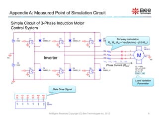
• From the 3-Phase Induction Motor specification, the model is characterized by setting parameters
LL, RLL, KE, KT and LOAD.
All Rights Reserved Copyright (C) Bee Technologies Inc. 2012 2](https://image.slidesharecdn.com/about3-phaseacmotormodelpsspiceopen-120806213700-phpapp02/85/3-AC-2-320.jpg)
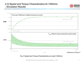
![2.4) Power Output and Efficiency Characteristics At 140Arms
- Simulation Results
At Load=140Arms, Power Output ≈ 13.7 [KW]
Watt
At Load=140Arms, Efficiency ≈ 82 [%]
[%]
Reference of Phase U
Fig. 6 Power Output and Efficiency Characteristics at Load=140Arms
All Rights Reserved Copyright (C) Bee Technologies Inc. 2012 7](https://image.slidesharecdn.com/about3-phaseacmotormodelpsspiceopen-120806213700-phpapp02/85/3-AC-7-320.jpg)

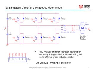
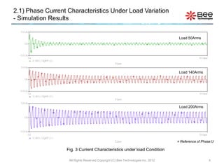
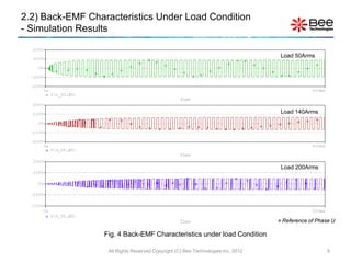
The document summarizes an SPICE model of a 3-phase AC motor that can accurately reproduce: (1) frequency characteristics (impedance characteristics), (2) reverse electromotive force characteristics, and (3) physical characteristics. It provides details on parameter settings for the model, the simulation circuit diagram, and simulation results showing characteristics like phase current, back-EMF, speed, torque, power output, and efficiency under varying load conditions.


