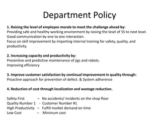
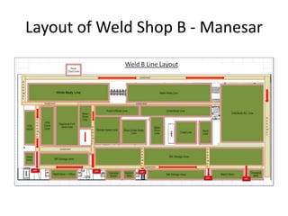
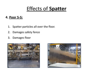
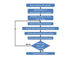
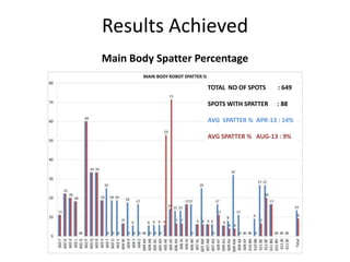
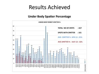
2. Introduction of Plant
Weld Shop B Plant is the second weld shop of Maruti Suzuki India Limited (MSIL)
in Manesar Plant. This is the fifth plant in MSIL overall including Gurgaon Plants.
The model which is manufactured over here is Swift (YP8). The plant was set up
to produce two models namely Swift (YP8) and Ritz (YV4) with a planned capacity
of 2,50000 bodies per, but due to ever increasing market demand of Swift,
WSMB worked hard to increase the YP8 capacity from 1,60,000 to 2,50,000. A lot
of automations were carried out to improve the capacity.
Weld Shop B has 100% automation.
3. Department Policy
1. Raising the level of employee morale to meet the challenge ahead by:
Providing safe and healthy working environment by raising the level of 5S to next level.
Good communication by one to one interaction.
Focus on skill improvement by imparting internal training for safety, quality, and
productivity.
2. Increasing capacity and productivity by:
Preventive and predictive maintenance of jigs and robots.
Improving efficiency
3. Improve customer satisfaction by continual improvement in quality through:
Proactive approach for prevention of defect. & System adherence
4. Reduction of cost through localization and wastage reduction.
Safety First – No accidents/ incidents on the shop floor
Quality Number 1 - Customer Number #1
High Productivity – Fulfill market demand on time
Low Cost – Minimum cost
5. Overview
Following Model is manufactured in Weld Shop Manesar B -
YP8 (Swift) : Lxi, Vxi, Zxi ; Ldi, Vdi, Zdi
The body panels produced in the press shop and the other small components
(supplied by the vendors) are joined here to give the “white body” or “shell”. In
a typical car body, total 2684 welds are done.
The weld shops have the following facilities.
• Welding jigs
• Portable Spot welding guns
• Spot Welding robots
• CO2 Welding robots
• Hemming machines
• Sealer Application units
• Number Punching machines
6. Division of Weld Shop B
1. UNDER BODY: Here different underbody panels are welded together. These comprises
of rear underbody, central underbody, front engine room panel. These underbody panels
are prepared on sub line starting from singular components. The sub lines have specific
jigs for each. There are chain hosts for transferring the jobs from one jig to another on sub
lines. Finally these underbodies are put on the conveyor and welded together to give the
underbody. The chassis no. is punched on the cowl top and it is welded to the front engine
room panel.
7. Division of Weld Shop B
2. MAIN BODY: As the body moves on the conveyor, roof and side body panels are welded
to it to give the main body. The side body panels are prepared on the sub lines. Each side
body consists of an inner side body and an outer side body. All the spots are welded onto
the inner side body which is welded onto the outer side body.
8. Division of Weld Shop B
3. WHITE BODY: The White Body line is common for both line-1 and line-2. The
doors, hood and back door are attached onto the main body with the help of bolts and
screws to make it a “white body”. The body is checked for dents, burr and spatter and
these defects are repaired. After inspection and repairs the body is called WBOK. It is sent
to the paint shop thereafter.
9. Welding Techniques used in Weld Shop B
For welding purpose, the following welding techniques are used
in the Weld shop:
• Resistance welding.
• MIG welding.
• Gas welding.
• Precision welding.
10. Resistence Welding
Resistance welding basically consists of spot welding. In this process, an electric
current flows through a resistive circuit to generate enough heat between two pieces
of sheet metal so that the metal reaches molten stage .The resistance to the flow of
current is provided by the work piece. The maximum heat is generated at the point of
maximum resistance.
* Weld Current
* Weld Time
* Pressure
* Electrode Press
Heat Generated is given by:
H=I2xRxT.
H = Heat.
I2 = Current in amperes.
R = Resistance of the work in ohms.
T = Time the current flow in cycles.
11. Equipment used for Spot Welding
Type of gun Definition Advantages Disadvantages
a) PSW - Portable
spot welding gun
These are the conventional
type and consist of
transformer, timer, kick less
cable, sub-cable etc
Light in weight, easy handling. a) High in Maintenance
b) Energy losses are high.
c) Consumable cost high
b) IT Guns (Integrated
Transformer)
IT gun (Integrated
transformer) - Transformer
and timer forms an integral
part of the weld gun and
welding parameters are
controlled by the
Microprocessor.
A) Energy losses are one third
of PSW.
B) Low maintenance.
C) High spot quality and
consistency
D) safe
a) Heavy in weight.
b) Handling not easy
compared to PSW
c) SSW (static spot
welding gun).
Such gun are static and stand
on one place and work like
PSW.
Instead of gun, component is
handled. So easy working.
Set up is robust. So no
movement. Can work only on
one place.
d) Servo Gun Such gun uses servo motor
power in place of Pneumatic
power for gun arm movement.
Installed basically in robots.
a) Energy losses low. b) Low
maintenance.
c) High spot quality and
consistency.
d) safe.
e) No Pneumatic power, so
better tip force control.
Heavy in weight.
Electricity consumption
relatively high compared to
Pneumatic IT guns.
12. MIG WELDING
This is a modern Arc welding technique which uses an inert gas atmosphere in place of
flux and has auto feeding. This technique is used specially, for welding of thin sheets. In
sheet metal work, this technique is extensively used. Inert gases like Argon are mainly
used. CO2 gas is relatively cheap to Argon and has similar inert property. So in mass
production, where finishing quality is not much required, CO2 gas is used in place of
Argon. That’s why, the MIG welding which uses CO2 gas for inert atmosphere is called
CO2 Welding.
Parameters of CO2 welding -
• Voltage : 16-24 V
• Current : 60-100 A
• CO2 Flow Rate : 16-20 Lt/min
13. Gas Welding
BRAZING:
Brazing is defined as a joining process wherein coalescence is produce by heating to a
suitable temperature and by using a filler metal having a melting point above 427oC
and below the melting point of base metal.
This is a non fusion process in which a dissimilar filler material fills the gap between
close fitted surfaces of joining parts through capillary rise.
SOLDERING:
It’s also a joining process similar to Brazing, but with a difference in temperature.
Soldering is done below the 427oC.
This joining process is suitable for low application of heat.
Example - Body outer skin is very sensitive to heat. So any repairs like dent etc are
repaired by soldering.
14. Precision Welding
The stud welding is being done in Weld Shop, through precision welding.
The welding instruments consist of controller, feeder, cable, feed pipe, gun
etc.
15. Project Contents
• What is Spatter?
• Need and scope of Spatter Reduction
• Reasons for Spatter
• Effects of Spatter
• Flowchart of procedure
• Activities done for Spatter Reduction
• Results achieved AFTER Spatter Reduction
• Learning
16. What is Spatter?
The small particles of molten
metallic material that are expelled
during spot welding, are called
spatter.
17. Need and Scope of Spatter Reduction
Project
• Currently weld spatter is a major concern as per
1. Safety : Injuries to workers handling weld robots
2. Cost and Quality standards : Spatter sticking to work
pieces and tooling
3. Cost standards : Loss of material
• High spatter percentage currently.
• Moving towards full automation in welding processes is
good scope for significant spatter reduction.
18. Reasons for Spatter
1. Dust & contamination in sheet metal parts
2. Gap between work piece, electrode & work piece
3. Tip angle not perpendicular to surface of work piece
4. Improper Tip dressing
5. Tip mismatch
6. Parameters including current, pressure & cycle time are set
higher than required.
19. 1. Dust and Contamination in Sheet Metal Parts
RustDust
20. 2. Gap between work piece
Gap b/w sheets Gap b/w tips
Movable tip
Fix tip
Gap
21. 3. Tip angle not perpendicular to surface of work
piece
Non-
Perpendicular
22. 4. Improper Tip dressing
Tip wear from
one side only
Improper gun
angle
Tip
Dresser
25. Effects of Spatter
1. Safety Loss:
1. Can harm/burn skin
3. Burns clothes
4. Damages belongings
2. Spatter particles can cause Eye Injuries ( Safety goggles mandatory)
26. Effects of Spatter
2. Quality Loss:
1. Spatter particles clog the jig miller, block & deform the
body structure and decrease body accuracy.
2. Spatter particles on Clamp lead to Improper Clamping of
body.
3. Spot Undulation on Body.
4. Spot Puncture on Body.
27. Effects of Spatter
3. Production Loss:
1. Welding jigs – Spatter particles clog on the cylinders &
clamps and blocks their functioning.
2. Jams Shuttle and NC Locator movement
3. Damages wires, cables and sensors
4. Clogging of spatter on PLS, Reed switch obstructs their
signal visibility.
28. Spatter clog at jigs Spatter clog on wires
3. Production Loss:
29. Effects of Spatter
4. Poor 5-S:
1. Spatter particles all over the floor.
2. Damages safety fence
3. Damages floor
31. Identification of
spots/Robots with spatter
Schedule number of spots
with spatter
Data collection for spatter
Check for
Spot with
Spatter
Result compilation
Ok
Shank matching correction
Check and correct Dressing position
Check and correct Spot position
Check and correct Sheet gap
Not ok
34. List of Activities Carried Out for
Spatter Reduction
1. Shank Misalignment Corrected
2. Improper Gun angle during tip dressing corrected
3. Improper Gun angle during welding corrected
4. Gap between tip and work piece reduced
5. Parameter change
42. Main Body Spatter Percentage
Results Achieved
TOTAL NO OF SPOTS : 649
SPOTS WITH SPATTER : 88
AVG SPATTER % APR-13 : 14%
AVG SPATTER % AUG-13 : 9%
43. Under Body Spatter Percentage
Results Achieved
TOTAL NO OF SPOTS : 657
SPOTS WITH SPATTER : 161
AVG SPATTER % APR-13 : 25%
AVG SPATTER % JULY-13 : 16%
44. • Layout and Process of Weld Shop B
• Spatter Reduction Procedure using Different
Techniques, as well as Procedure Efficiency
• Basic Robotic Operation
• Operation Analysis System(OAS)
• Stop Rate Analysis for Line Efficiency.
Project Learning