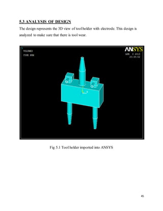
The document discusses various welding processes used by a company including arc welding, metal inert gas welding, TIG welding, stud welding, and spot welding. It provides details on each process and how they work. Spot welding is described as using two electrodes to concentrate current and heat the metals to the melting point, forming a weld. The document also covers resistance welding theory, timing controls for weld time and sequence, electrode force, and proper installation of spot welding machines.
This document provides an introduction and overview of a thesis investigating the use of Cold Metal Transfer (CMT) cladding to produce wear and corrosion resistant coatings. The thesis will study and optimize the operating parameters of CMT cladding for specific base and filler materials. CMT welding is considered a novel joining method that is process stable, reproducible, and cost-effective. The document outlines the goals and scope of the thesis research, which will collect experiment data from Centria University to analyze CMT cladding.
* Basics of Induction heating and heat treating
* Role and specifics of induction technology in heat treating in automotive parts
* Main processes of induction heat treating of automotive parts
* Computer simulation and optimization of induction processes and heating coils
* Advanced design of induction coils
* Magnetic controllers on induction coils
* Induction coil manufacturing
* Maintenance of induction coils
* Stresses and distortions in the process of induction heating
* Examples of induction heat treating (parts, processes, coils, installations)
* Conclusions
This presentation provides an overview of forge welding, including its principles, classification, process parameters, temperature requirements, tools needed, forgeable metals, common hand tools, advantages, disadvantages, and applications. Forge welding is a solid-state welding process that joins two pieces of metal by heating them above 1000 degrees Celsius and hammering them together. It can be done via hammer welding, roll welding, or die welding and is used in industries like aerospace, shipbuilding, and manufacturing.
This document discusses shaped tube electrolytic machining (STEM), which is a variation of electrochemical machining (ECM) that can produce small holes with high depth-to-diameter ratios in electrically conductive materials. STEM uses a cathodic tool in the shape of a conducting cylinder with an insulating coating to drill holes in an anodic workpiece when an electric potential is applied through an electrolyte, typically an acid. The document outlines the STEM process, parameters including electrolytes, voltage, time and feed rate, capabilities including hole size and tolerances, advantages, limitations, and applications for drilling cooling holes in parts like turbine blades.
Electro Stream Drilling (ESD) is an electrochemical machining process that uses a high velocity stream of negatively charged acidic electrolyte to drill small diameter holes. It can drill holes between 0.127-0.89 mm using a voltage of 150-850 V. Unlike conventional electrochemical drilling, debris dissolved in the acidic electrolyte prevents clogging. ESD can drill deep and accurate holes through either dwell drilling or penetration drilling methods and offers advantages like high aspect ratio holes, low surface roughness, and no burrs or residual stresses. However, it has high initial costs and is limited to electrically conductive materials.
Spot welding is a metal joining process where two metal surfaces are welded together by resistance heating when a large current is passed through them. The current causes the metal to heat up and melt together. It allows for quick and easy welding of multiple metal sheets simultaneously without filler metals or flames. However, spot welds have lower strength than other weld types and repairs can be difficult. It is commonly used in the automobile industry to join metal car body panels and parts.
Resistance welding is described as an electric welding process where heat is generated by resistance of the workpieces to electric current in a circuit. Pressure is applied simultaneously with current to produce coalescence. Common resistance welding techniques include spot welding, seam welding, projection welding, and flash butt welding. Spot welding involves passing current through overlapping metal sheets held between electrodes to create nugget welds. Seam and projection welding can continuously weld moving sheets using arrays of electrodes.
Ultrasonic welding is a solid state welding process that uses high-frequency vibrations to weld materials together without melting them. The process involves applying static pressure to the workpieces while a sonotrode transmits ultrasonic vibrations parallel to the welding interface. This causes localized plastic deformation and heating through friction at the interface, producing a weld. Ultrasonic welding is used to join thin materials and can weld dissimilar metals. It has advantages like minimized heat affected zones and ability to weld delicate materials. Applications include electronics, automotive, medical devices, and packaging.
This document provides an overview of resistance welding, including resistance spot welding, projection welding, and seam welding. It discusses key factors that affect heat generation in resistance welding such as welding time, current, and resistance. The document also examines electrode materials and geometry, welding problems such as expulsion and shunting effects, and mechanical testing of resistance spot welds.
The document discusses various methods for plastic welding, including mechanical joining using fasteners, adhesive bonding, and different types of welding. It describes several welding processes such as hot plate welding, hot gas welding, ultrasonic welding, friction welding, and laser welding. These welding methods use heat from external sources like hot plates or internal sources like ultrasonic vibrations to melt the plastic surfaces and join them together. Common applications of plastic welding include pipe assemblies, automotive parts, and food packaging.
The material removal in EDM occurs due to the formation and collapse of plasma channels between the tool and workpiece. When a potential difference is applied, electrons are emitted from the tool and strike the workpiece, generating heat and forming craters. The main components of an EDM system are a power supply, workpiece and tool made of conductive materials, a dielectric medium like kerosene or water, and a servo control unit. Process parameters like voltage, current, pulse duration, and spark gap influence the material removal rate and surface finish. EDM can machine hard metals and complex shapes that other methods have difficulty with.
Welding is a fabrication technique that joins materials together by heating them to suitable temperatures using various heat sources like electric arcs or gas flames. There are different types of welding processes categorized by the heat source and filler material used, such as arc welding, gas welding, resistance welding, and solid state welding. The document focuses on three main arc welding processes: shielded metal arc welding uses a consumable electrode covered in flux; gas metal arc welding uses a continuously fed wire electrode and shielding gas; and gas tungsten arc welding uses a non-consumable tungsten electrode and separate shielding gas and filler material. Each process is illustrated and their characteristics are compared. Common welding defects are also briefly discussed.
Frictional welding is a solid-state welding process that uses relative motion and high force between two contacting workpieces to generate heat through friction and form a joint. There are different types of frictional welding processes defined by the motion used - linear, rotary, stir, radial, and orbital friction welding. Frictional welding produces joints with low surface impurities and narrow heat-affected zones. It can join similar and dissimilar metals for applications in automotive, aerospace, consumer products, medical, and other industries.
Vacuum and plasma surface hardening are heat treatment processes carried out in low-pressure environments to impart high wear resistance and mechanical properties to steel components. Vacuum surface hardening involves heating steel above 1000°C in a vacuum to allow uniform hardening without oxidation. Plasma surface hardening uses ionized gas plasma to accelerate the carburizing or nitriding process, allowing shorter cycle times and treatment of materials prone to oxidation. Both methods provide oxide-free surfaces and excellent mechanical properties but require higher initial capital costs than conventional carburizing.
The document discusses parameters that must be considered when performing spot welding, including electrode force, electrode diameter, squeeze time, weld time, hold time, and weld current. It provides target values for these parameters based on sheet thickness. The determination of optimal parameters is complex as changes to one parameter affect others. Parameters must be optimized for weld quality, electrode wear, and equipment capabilities.
Electron Beam Welding is a fusion welding process in which a beam of high-velocity electrons is applied to the material to be joined. The work-piece melt as the kinetic energy of the electrons is transformed into heat upon impact. The EBW process is well-positioned to provide industries with highest quality welds and machine designs that have proven to be adaptable to specific welding tasks and production environments.
The document provides information on Electrical Discharge Machining (EDM). EDM is a manufacturing process where electrical discharges are used to erode material from a workpiece to achieve a desired shape. In EDM, a series of sparks erode material by rapidly recurring electrical discharges between two electrodes separated by a dielectric liquid and subject to an electric voltage. One electrode is the tool that shapes the workpiece. Material removal occurs through thermal melting and vaporization caused by the extreme heat of electrical sparks between the electrodes.
Here I have explained theoretical view of ultrasonic welding and its applications in real world.
In addition to that, advantages and disadvantages of this process also discussed.
High-frequency welding is included in a group of resistance welding process variations that use high-frequency welding current (1kHz to 800kHz) to concentrate the welding heat at the desired location.
The heat produces the coalescence of metals, and an upsetting force usually is applied to produce a forged weld.
High-frequency resistance welding is an automated process and is not adaptable to manual welding.
High-frequency resistance welding was developed during the late 1940s and early 1950s to fill the need for high-integrity butt joints and seam welds in pipe and tubing.
But today the process is also used in the manufacture of products such as spiral-fin boiler tubes, closed roll form shapes, and welded structural beams.
A wide range of commonly used metals can be welded, including low-carbon and alloy steels, ferritic and austenitic stainless steels, and many aluminum, copper, titanium, and nickel alloys.
HFW is based on two main electrical phenomena
Skin effect
Proximity effect
Electric arc welding is a process that joins metals by heating them with an electric arc between an electrode and the metals. It is one of the most common welding processes and uses a consumable electrode coated in flux to lay the weld. The electric arc melts the tip of the electrode and filler metal is deposited into the weld pool while the flux provides shielding from contamination and leaves a slag layer. Proper welding techniques along with the right equipment, electrodes, and power source are required to perform arc welding.
This document discusses different types of plastic welding. It describes five main types: hot gas plastic welding, laser welding, hot plate plastic welding, ultrasonic plastic welding, and friction welding. For each type, it provides details on the welding process and how heat is applied to fuse plastic materials. The document also covers the advantages of plastic welding, such as its speed, cleanliness, and ability to create permanent welds. Disadvantages include the permanence of welds and costs associated with some methods. Applications are in automotive and other industries where plastic welding provides a fast, lightweight joining method.
1. Welding is a metal joining process that involves applying heat, pressure, or both to joining materials. There are several types of welding processes including solid state welding, fusion welding, and pressure welding.
2. Solid state welding joins metals below their melting point using mechanical pressure and heat. Examples are cold welding, ultrasonic welding, friction welding, and friction stir welding.
3. Resistance welding generates heat for welding through electrical resistance across components. Common resistance welding methods are spot welding, seam welding, and projection welding.
the slide shows the advance welding technic like as Tig And Mig Welding Process.
it help people to understand the advance manufacturing process for welding.
it made by Sk Samsuddin.
This document discusses laser beam welding, including what a laser beam is, the different types of lasers, and the laser beam welding process. It describes how laser beam welding works by focusing an intense laser beam onto metal workpieces to melt and join them. The document outlines the history of lasers from Einstein's theories to developments in the 1970s-2000s. It also explains the principles and setup of laser beam welding, the different types (conduction and keyhole welding), applications, and provides an example of repairing nuclear power plant components using ND:YAG laser welding.
Ultrasonic welding uses high-frequency sound waves to melt and bond materials like plastics and thin metals together without needing bolts, solder, or adhesives. The sound waves generate heat through friction to join the materials in under 3 seconds. It allows for precise welding of very thin materials with minimal surface deformation or defects. However, it is best for thin materials and may not be economical for all applications.
Demand of welding increase of new materials.
-- ceramics and metal matrix composites.
-- High strength low-alloy (HSLA) steels
Lack of skilled labours
Traditional welding techniques are costly
Safety concerns.
Need to improve the total cost effectiveness of the welding
Lalit Yadav
The document discusses underwater welding technology. It describes how underwater welding was first developed by the British Admiralty and then special waterproof electrodes were created. It discusses the different types of underwater welding including wet welding, dry welding using hyperbaric chambers, and different habitat sizes. It outlines the challenges of underwater welding including costs and equipment needs. It also discusses the welding processes, necessary equipment, safety considerations, and developing automation trends in the field.
1) A portable spot welder was developed for home use as conventional spot welders are large, expensive, and not suitable.
2) The portable spot welder uses a transformer circuit and electrodes to produce spot welds, allowing easy welding of small items.
3) It is small, inexpensive, efficient and suitable for light duty home use welding jobs.
Spot welding is a process that joins metal surfaces by applying heat generated from resistance to electric current flowing between two metal sheets clamped together by electrodes. When a large current passes through the joint, it generates heat due to resistance and melts the metals, fusing them together. The basic steps are to squeeze the sheets together with electrodes, apply an alternating current to generate heat and melt the metals, hold the heat, forge the weld by continuing pressure, then remove pressure to cool. Spot welding is commonly used in automotive manufacturing and other industries due to its speed, not requiring filler metals, and ability to simultaneously weld multiple sheets.
Spot welding /certified fixed orthodontic courses by Indian dental academy Indian dental academy
The document discusses a project to develop a controller to better control the strength of spot welds. Spot welding involves applying heat and pressure via electrodes to join metal sheets. Currently, weld strength is controlled mainly by current, but the project aims to also control force during welding for more consistency. The controller will integrate both current and force control. This may help address issues like electrode wear and expulsion which cause strength variations. The developed controller will be used to study welding dissimilar metals and different thicknesses.
This document describes a diploma project modeling a proton exchange membrane fuel cell (PEMFC) using COMSOL Multiphysics. It presents a two-dimensional, non-isothermal model of the porous cathode-anode gas diffusion layer. The model accounts for single-component species diffusion but not liquid water transport. Tables provide reactions on fuel cell electrodes and parameters used in the COMSOL model. The effect of changing operating conditions like humidity is explored. It is found that humidity has a major impact on electrical potential and current density across the electrodes.
This document defines robots and describes different types of industrial robots. It begins by defining a robot as a machine that can carry out complex actions automatically through programming to resemble human movements and functions. The main components of a robot are then outlined as the robot arms, sensors, end parts, controller, and drive. Several common types of industrial robots are also described, including Cartesian, cylindrical, spherical/polar, SCARA, articulated, and parallel robots. Each robot type is suited for different assembly or manufacturing tasks.
Welding is a process that joins materials by heating them to melt or soften them and allowing them to cool, forming a permanent bond. It is commonly used to join metal parts in manufacturing. Some key types of welding include arc welding, gas welding, resistance welding, and solid state welding. Welding is used in many industries such as automotive, aerospace, shipbuilding, and construction.
This document provides an overview of robots and robotics. It defines a robot as a re-programmable machine that can perform tasks automatically in place of humans, especially in hazardous environments. The document then discusses the history and origins of the words "robot" and "robotics." It also outlines some of the key parts of industrial robots like sensors, effectors, actuators, controllers, and arms. Finally, it briefly describes different types of robots and their applications as well as some advantages and disadvantages of robotics.
The document discusses the benefits of exercise for both physical and mental health. It notes that regular exercise can reduce the risk of diseases like heart disease and diabetes, improve mood, and reduce feelings of stress and anxiety. The document recommends that adults get at least 150 minutes of moderate exercise or 75 minutes of vigorous exercise per week to gain these benefits.
Electric welding involves joining metals through heat generated by an electric current. There are several types of electric welding processes. Resistance welding uses high current to heat and join metals at points of contact between electrodes and generates heat based on resistance. Arc welding uses an electric arc to melt metals and can use consumable or non-consumable electrodes with shielding gas. Carbon arc welding is a process that produces coalescence of metals by heating them with an arc between a non-consumable carbon electrode and workpiece.
The document discusses shielded metal-arc welding equipment and processes. It describes the basic components of shielded metal-arc welding including the welding machine, cables, electrode holder, electrodes, and other accessories. It explains the different types of welding machines like motor-generators, transformers, and rectifiers. It also discusses important electrical terms, electrode selection, safety equipment, and welding procedures. The key points are that shielded metal-arc welding uses a coated electrode to generate an arc to melt and join metals, it requires various equipment operated and maintained properly, and there are many electrode and safety considerations for this welding process.
This document provides information on various welding processes and technologies. It begins by defining welding as a process of joining metal pieces through atomic diffusion or by melting and fusing them together. Some key welding processes discussed include shielded metal arc welding, gas tungsten arc welding, resistance spot welding, and flash welding. The document also covers principles of arc welding, types of weld joints, and advantages and disadvantages of different welding methods.
This document provides information on various welding processes and technologies. It begins by defining welding as a process of joining metal pieces through atomic diffusion or by melting and fusing them together. Some key welding processes discussed include shielded metal arc welding, gas tungsten arc welding, resistance spot welding and flash welding. The document also covers principles of arc welding, types of weld joints, and advantages and disadvantages of different welding methods.
This document provides information on various welding processes including resistance welding, spot welding, seam welding, projection welding, percussion welding, thermit welding, friction welding, explosive welding, ultrasonic welding, and diffusion welding. It explains the basic principles, equipment, and applications of each process. Resistance welding generates heat through resistance to electric current and is commonly used for sheet metal. Spot welding uses electrodes to create overlapping welds. Seam welding produces a continuous air-tight seam.
i have made a presentation on welding and welding transformer, here i included types of weldings and their advantages and types of welding transformer and their working, construction, application, advantages..
Seminar report on electric discharge machineAnkit Amlan
This document provides a seminar report on electric discharge machining (EDM) by Ankit Amlan, a 7th semester mechanical engineering student at VSSUT, Burla. The report details EDM work done by Amlan at Hindustan Aeronautics Limited in Sunabeda. It covers the history of EDM, working principles, material removal mechanisms, types of EDM including sinker and wire-cut, applications, and advantages/disadvantages. Pictures and diagrams are included to illustrate EDM systems and processes.
Resistance welding is a welding process that uses heat generated by resistance to electric current passing through the workpieces. There are several types of resistance welding including spot welding, seam welding, projection welding, flash welding, upset welding, percussion welding, and high frequency resistance welding. Spot welding is commonly used in automotive manufacturing to join vehicle body parts and involves applying pressure and electric current between two electrodes to weld metal sheets together.
Welding /certified fixed orthodontic courses by Indian dental academy Indian dental academy
The Indian Dental Academy is the Leader in continuing dental education , training dentists in all aspects of dentistry and offering a wide range of dental certified courses in different formats.
Indian dental academy provides dental crown & Bridge,rotary endodontics,fixed orthodontics,
Dental implants courses.for details pls visit www.indiandentalacademy.com ,or call
0091-9248678078
Electric resistance welding is a type of pressure welding that uses electric current and mechanical pressure to join metal pieces. Heat is generated at the interface when a current passes through for a short duration. When the area reaches temperature, pressure is applied until the weld solidifies. Common types of electric resistance welding include spot welding, seam welding, and projection welding, which are used to join overlapping metal sheets or wires at high production rates.
Spot welding /certified fixed orthodontic courses by Indian dental academy Indian dental academy
The Indian Dental Academy is the Leader in continuing dental education , training dentists in all aspects of dentistry and offering a wide range of dental certified courses in different formats.
Indian dental academy provides dental crown & Bridge,rotary endodontics,fixed orthodontics,
Dental implants courses.for details pls visit www.indiandentalacademy.com ,or call
0091-9248678078
Pulsed MIG welding is a modified spray transfer welding process where the welding current is pulsed between a high peak current and a low background current at regular intervals. This pulsation allows for detachment of uniform molten droplets from the electrode wire. Pulsed MIG welding offers advantages like wire and gas savings, reduced spatter, improved productivity, and the ability to weld a wider range of metals. While offering these benefits, pulsed MIG welding also requires more expensive equipment and shielding gases compared to conventional MIG welding. It finds applications in welding of structural steel, aluminum, stainless steel, and some offshore applications.
This document presents information about electric welding. It discusses different types of electric welding including resistance welding. Resistance welding involves applying pressure and an electric current to heat and join two metal pieces. The current passes through the metal pieces, generating heat due to resistance at the joining interface. This heat softens the metals allowing them to fuse together under pressure. Resistance welding is commonly used in manufacturing due to its speed, ability to join similar and dissimilar metals, and suitability for mass production applications.
The document discusses shielded metal-arc welding, also known as stick welding. It is a manual welding process that uses an electrode coated in flux to create an electric arc to melt metals being joined. The arc produces intense heat, around 10,000 degrees Fahrenheit. The flux protects the weld area from contamination and provides shielding. The document describes the basic equipment used, including welding machines powered by generators or transformers to produce the necessary current, electrode holders, cables, and electrodes. Safety precautions for shielded metal-arc welding are also outlined.
Group 3's document discusses electrical welding and its types. It provides information on different welding processes like fusion welding, non-fusion welding, resistance welding, arc welding, metal arc welding, carbon arc welding, atomic hydrogen welding, butt welding, seam welding, and projection welding. It also discusses the use of direct current and alternating current in welding and classifications of arc welding. Laser welding is also introduced at the end.
This document provides an overview of various joining processes, including fusion welding processes like gas welding, arc welding, TIG welding, MIG welding, plasma arc welding, and electron beam welding. It also discusses solid-state welding processes and resistance welding processes like spot welding and seam welding. Specific details are provided on plasma arc welding and resistance welding, including their principles, advantages, and applications.
The document discusses various welding processes including gas welding, arc welding, MIG welding, and TIG welding. It provides details on the principles, equipment used, advantages and disadvantages of each process. Some key points:
- Welding joins metals through heating and fusion. Common processes are oxy-acetylene gas welding, SMAW, GMAW (MIG), and GTAW (TIG welding).
- Gas welding uses a flame to heat and fuse metals. MIG welding continuously feeds a wire electrode to form the weld. TIG welding uses a non-consumable tungsten electrode and inert gas shield.
- Advantages include strong joints, cost effectiveness, versatility. Dis
1. 1
CHAPTER 1
INTRODUCTION
List of welding processes prevailing in the company
• Arc welding
• Inert Gas (CO2) welding
• Spot welding
• Stud Welding
• TIG Welding
1.1 ARC WELDING:
Arc welding is a type of welding that uses a welding power supply to create
an electric arc between an electrode and the base material to melt the metals at the
welding point. They can use either direct (DC) or alternating (AC) current, and
consumable or non-consumable electrodes. The welding region is usually protected
by some type of shielding gas, vapour, or slag. Arc welding processes may be
manual, semi-automatic, or fully automated. First developed in the early part of the
20th century, arc welding became commercially important in shipbuilding during
the Second World War. Today it remains an important process for the fabrication
of steel structures and vehicles.
1.2 METAL INERT GAS WELDING:
Metal inert gas (MIG) welding or metal active gas (MAG) welding, is a
welding process in which an electric arc forms between a
consumable wire electrode and the work piece metal(s), which heats the work
2. 2
piece metal(s), causing them to melt, and join. Along with the wire electrode,
a shielding gas feeds through the welding gun, which shields the process from
contaminants in the air. The process can be semi-automatic or automatic. A
constant voltage, direct current power source is most commonly used with
GMAW, but constant current systems, as well as alternating current, can be used.
There are four primary methods of metal transfer in GMAW, called globular,
short-circuiting, spray, and pulsed-spray, each of which has distinct properties and
corresponding advantages and limitations.
1.3 TIG WELDING
Tungsten inert gas (TIG) welding is an arc welding process that uses a non-
consumable tungsten electrode to produce the weld. The weld area is protected
from atmospheric contamination by an inert shielding gas(argon or helium), and
a filler metal is normally used, though some welds, known as autogenous welds, do
not require it. A constant-current welding power supply produces energy which is
conducted across the arc through a column of highly ionized gas and metal vapours
known as a plasma.
1.4 STUD WELDING:
Stud welding is a form of spot welding where a bolt or specially formed nut is
welded onto another metal part. The bolts may be automatically fed into the spot
welder. Weld nuts generally have a flange with small nubs that melt to form the
weld. Studs have a necked down, un-threaded area for the same purpose. Weld
studs are used in stud welding systems.
Capacitor discharge weld studs range from 14 gauge to 3/8" diameter. They can
come in many different lengths ranging from 1/4" to 5" and larger. The tip on the
weld end of the stud serves a twofold purpose.
3. 3
1.5 SPOT WELDING:
Spot welding is a process in which contacting metal surfaces are joined by the heat
obtained from resistance to electric current. Work-pieces are held together under
pressure exerted by electrodes. Typically the sheets are in the 0.5 to 3 mm (0.020
to 0.12 in) thickness range. The process uses two shaped copper alloy electrodes to
concentrate welding current into a small "spot" and to simultaneously clamp the
sheets together. Forcing a large current through the spot will melt the metal and
form the weld. The attractive feature of spot welding is a lot of energy can be
delivered to the spot in a very short time .
The amount of heat (energy) delivered to the spot is determined by the resistance
between the electrodes and the amperage and duration of the current. The amount
of energy is chosen to match the sheet's material properties, its thickness, and type
of electrodes. Applying too little energy won't melt the metal or will make a poor
weld. Applying too much energy will melt too much metal, eject molten material,
and make a hole rather than a weld. Another attractive feature of spot welding is
the energy delivered to the spot can be controlled to produce reliable welds.
The advantages of the method include efficient energy use, limited work
piece deformation, high production rates, easy automation, and no required filler
materials. While the shear strength of each weld is high, the fact that the weld spots
do not form a continuous seam means that the overall strength is often significantly
lower than with other welding methods, limiting the usefulness of the process. It is
used extensively in the automotive industry cars can have several thousand spot
welds.
4. 4
CHAPTER 2
LITERATURE SURVEY
2.1 RESISTANCE WELDING THEORY
Resistance welding process is applicable for joining electrically conducting aerials,
the joint s are made by raising the temperature of the weld zone and the parts
together during the plastic stage. Spot welding projection welding seam welding
and upset butt welding are all basically resistance welding, the difference are
mainly in the geometrical arrangement of parts. In all these cases the heat required
to raise the temperature of the metal is generated due to the passage of electrical
current through the joint. The contact resistance (of the order of milli ohms) causes
the heat to localize at the point of interest and the current carrying electrodes are
adjusted to increase this effect. No fillers are required therefore the process is
cheaper, neater and faster than most of the other methods of metal joining.
CURRENT SOURCE:
The source of current is in general a special step down transformer. The primary
side of this fed from the power supply. In small machines up to about (5kva) the
transformers are designed to work from 220 volts ac. In case of larger machines the
power is fed from 2 lines of a three phase 440 volts system. Another type of power
source employed consists of a regulated dc supply which is momentarily connected
to a pulse transformer. Since any machine should be adaptable for different jobs,
normal type of resistance welding transformer is provided with a number of taps on
its windings. The secondary voltage is thus adjusted depending upon the job to be
weld.
5. 5
2.2 TIMING CONTROLS:
2.2.1 WELD TIME:
A very important requirement of spot welding is that the welding current is
delivered to the job only for a very short time, typical timings are only about 0.1
sec to 3 sec. Precision welding of highest quality are done with a timing less than 1
sec therefore the unit of time preferred by the industry is the cycle. One cycle
corresponds to 1/50th of a second when referred to the power supply frequency of
50 cycles per second.
In simple machines a electromagnetic contactor is kept energised or a time period
suited to each requirement. The contacts of this conactor connect the primary of
the welding transformer to the power supply. The timing period is determined by
the settings of a variable resistor through which a capacitor is charged to a
predetermined level.
2.2.2 SEQUENCE TIMINGS:
A spot welding operator preferably must have to operate only a simple switch or a
foot lever. The electrodes should contact the job pieces and when a desired
pressure is developed the current should flow for a selected time and the electrodes
should part after the weld is forged.
In pneumatically operated machines the sequence of events as well as the duration
of each event are controlled by electronic timers. If the feeding of job is made fast
and regular it is possible to get a stitching type by recycling through the sequence
6. 6
2.2.3 SEAM WELDING:
For manufacturing leak tight drums and similar items the method used is seam
welding. Electrodes are rotating wheels the speed of which is adjustable. A series
of overlapping welds are made. Typical timings are 2 cycles on followed by 2
cycles off and periods. Heavy current 100-500 amps are therefore required to be
switched at the rate of 10-20 times a second and an electronic device is absolutely
necessary. There are several products which are produced by this type of welding
2.2.4 ELECTRODE FORCE:
Small and inexpensive machines utilize the force provided by the operator,
transferred through suitable lever mechanisms. Usually a spring is employed to
adjust the limit of force required when the spring is compressed to a set point a
switch is operated to start the weld.
Larger machines intended for heavy jobs and/or mass production utilizes
compressed air for delivering the force required. A pneumatic cylinder is
connected one of the welding electrodes and compressed air at a regulated pressure
is introduced into the cylinder at the start of the weld.
The pressure is removed after the weld is forged the switching of air being done by
an electromagnetic valve. In some equipments different pressures are utilized
during weld and forge. All the programmes is achieved through electronic controls.
7. 7
2.3 INSTALLATION OF SPOT WELDING MACHINE
The original installation of a piece of a equipment has a large bearing on its
subsequent operation and trouble free performance. This then deserves first
preference in the overall subject of service. This is especially true for resistance
welding machine because of the numerous utility services required electric power,
often two one for motor power and the other for the welding power. In addition the
welding machine may also require cooling water, air, hydraulic and sometimes
even gas services.
2.3.1 PREPARATION FOR INSTALLATION
Upon receipt the equipment should be checked thoroughly, with all packing lists,
instructions, special tools, etc., properly accounted for. Also at the time of receipt,
the machine, motor and control nameplates should be checked for proper service
requirements
2.3.2 SETTING THE MACHINE
Any machine that has mechanical motions, whether air hydraulic or electrical
actuation should be anchored to a rigid stationary surface to prevent creeping or
walking. The extent of this attachment to the floor or other surface will depend
upon the size weight or operation of the equipment also on the type of building or
floor. Pits are especially desirable for large splash welding machines to act as a
receptable for the flash metal from the weld. In any case the machine should be
leveled at its weight equally distributed on all legs or hold down member. Careless
setting of the machine may cause undue strain on its members or binding of ways
slides etc.
8. 8
2.3.3 SAFETY REQUIREMENTS
Safety for the operating personnel and the elimination of fire hazards are of
paramount importance. Welding equipment manufacturers provide their machine
with majority safety features. Adequate guarding of gearing and other moving
parts safe and approved electrical wiring as well as various types and kinds of
safety controls such as simple palm buttons to prevent operating the machine
without both hand on the buttons interlocks etc. Never attempt to override or evade
these safety measures. In addition users may install additional safety precautions:
area barricades exhaust systems, flash shield, etc. Rigorous maintenance of good
housekeeping procedures should be exercised at all the times.
2.3.4 ELECTRICAL INSTALLATION
With the machine set properly in position, electrical service is run through the weld
controls to the welding transformers and to the motors when required. The
electrical service to the motors will be the same as any normal electrical motor
service which is adequately covered by city or national electric codes.
The voltage rating of the cables used for welding transformer supply is important.
Welding cable which is not marked or stamped 600v is not acceptable for
resistance welding primary lines. The cable must a rating of 600v ac or above.
When machine are installed in a temporary manner a proper electrical earth found
must be provided to prevent electrically hazardous condition.
9. 9
2.3.5 SETUP OF EQUIPMENT
With the equipment completely installed and with electrical power turned off, the
installation personnel must:
1. Check motors for proper rotation.
2. Check all bolts , nuts etc., for tightness including electrical connections.
3. Check air water oil lines for possible leakages.
4. Make sure all cylinders function properly and see that hydraulic oil is adequate
5. If water saver valves are supplied the manual valve should be closed prior to
turning on the power for the first time. Turn on electrical power.
6. Turn on hydraulically operated equipment. After checking pumps for proper
rotation, it is necessary to exhaust all air from the system as any air at all, even a
bubble, may cause faculty operation.
7. See that all guards and safety devices are in place. Operate properly, and
adequately protect personnel from all moving parts of machine.
8. Set the weld control to the 'NO WELD' position. Set the 'SQUEEZE TIME',
'HOLD TIME' and 'COOL TIME' functions at maximum.
If everything is functioning properly , the machine is ready for the operating
department, which will set the machine and weld controls as required for the parts
to be joined. Proper weld schedules may be defined by the machine manufacturer,
to proceed with production.
10. 10
2.4 SERVICE REQUIREMENTS
2.4.1 Compressed air:
Moisture free air at a recommended flow volume is required at a working pressure
of 5.6kg/cm2.compressed air is useful for determining the reservoir size and flow
rate. The values are calculated without considering the piston rod diameter varies
for a given size of cylinder. The cylinder is supposed to work at 5.7 gauge pressure
and perform 100 operations.
2.4.2 Cooling water:
Clean residue water at minimum 2.1kg/cm2 pressure across machine and
temperature below 30 degree Celsius at recommended flow rate is required. Each
water cooling water circuit should have 5lpm flow rate hence cooling water rate
required is (5*n) plum, where n is the number of cooling water circuits.
2.5 COOLING SYSTEM
Resistance welding equipment develops very high secondary currents. this coupled
with compact design makes the need for proper cooling mandatory.
Water supply must be sufficient and at the proper temperature and pressure
difference as recommended.
If supply of city water does not meet specifications and if high in lime content , a
re-circulating system using distilled water should be considered.
11. 11
Water circulation should be checked often to assure that all parts of the welder
requiring cooling, receive water. Water flow should be checked at the outlet of the
machine.
If a water system becomes plugged or if flow gets restricted, an air line may be
utilized to remove the obstruction. The usual procedure is to remove both inlet and
drain lines from the machine and connect airline to the drain and force air in the
direction opposite to water flow.
When equipment is not to be used for a period of time, the water should be shut off
by closing the water shut off valve.
Hoses which have become worn, cracked or swollen should be replaced by new
ones. when replacing be sure that the water circuit is not changed. Cooling the
thyristor must always be considered important, Water should enter each tube at the
bottom of the metal jacket and be discharged at the top. the jumper hose in series
between two pads of the thyristor pair should be atleast 600mm long.
2.6 ELECTRODES AND DIES
All the high current generated by the water secondary is concentrated at the contact
points of the electrodes or dies. This current must be transmitted under pressure to
the work piece to be welded. Therefore, electrodes must have good electrical and
thermal conductivity and be able to withstand high pressures. It is important to
maintain the cleanliness and smoothness of electrode contact points to assure
consistent, good quality welds.
12. 12
Electrodes must be dressed whenever pitting, metal pickup or deformation is
noticed. Metal pickup by electrodes must be immediately removed before next
weld.
An adequate supply of spare electrodes is recommended to reduce downtime the
electrode dressing needed. Frequent cleaning of the electrode in the machine helps
maintain weld quality and lengthen the electrode replacement.
When dressing electrodes, always maintain the required contour. Electrodes often
have a radius or shape to conform to the part being welded or to properly
concentrate the weld current. A poorly dressed electrode directly contributes to
poor weld quality.
2.7 PNEUMATIC SYSTEM
Most machines will be entirely or partially air operated. For this reason basic
knowledge of pneumatics is essential for efficient welder maintenance.
The pneumatic system will usually consists of one or more of following items:
1. A filter(s)
2. A lubricator(s)
3. A regulator(s)
4. Valves
5. Cylinders
6. Intensifier (In Hydro-Pneumatic machines).
13. 13
All will require some type of maintenance to ensure proper and efficient operation.
It is good practice to have spares for each of the above so that the equipment
downtime can be minimized when extensive maintenance is required.
2.7.1 AIR LINE FILTER:
A filter, if used, may be of the manual or automatic type. The manual type will
require periodic removal of the trapped water and other foreign particles. Usually,
this is done by opening a petcock at the bottom of the bowl and catching the liquid
in a container. A filter with an automatic drain will empty itself as necessary.
occasionally, it will be necessary to replace or disassemble and clean the filter.
2.7.2 AIR LINE REGULATOR:
The air line regulator is used to reduce the supply line air pressure to the desired
pressure for welding. This adjustment is an important part of every weld schedule.
The regulator must be kept clean and operating accurately. Pressure losses and air
leaks can result from dirty regulators.
2.7.3 AIR LINE LUBRICATOR:
The lubricator should always contain oil at the specified level. The oil
recommended is a light machinery oil and is usually specified as a type having a
viscosity of 150 SSU at 100oF.
The oil level should never be above the line indicated on the bowl. When filling, be
sure that the air supply is turned off before removing the filter plug.
14. 14
All air systems require lubricating oil. The amount of the oil to be provided by the
lubricator cannot be specified but a good ' rule of thumb ' is one drop for each three
strokes of the most frequently operating cylinder. To adjust the lubricator, turn the
adjustment screw as indicated.
2.7.4 AIR VALVES:
Directional control valves are one of the most fundamental parts in hydraulic
machinery as well and pneumatic machinery. They allow fluid flow into different
paths from one or more sources. They usually consist of a spool inside a cylinder
which is mechanically or electrically controlled. The movement of the spool
restricts or permits the flow, thus it controls the fluid flow.
Manually operated valves work with simple levers or paddles where the operator
applies force to operate the valve. Spring force is sometimes used to recover the
position of valve. Some manual valves utilize either a lever or an external
pneumatic or hydraulic signal to return the spool.
Solenoid operated are widely used in the hydraulics industry. These valves make
use of electromechanical solenoids for sliding of the spool. Because simple
application of electrical power provides control, these valves are used extensively.
However, electrical solenoids cannot generate large forces unless supplied with
large amounts of electrical power. Heat generation poses a threat to extended use
of these valves when energized over time. Many have a limited duty cycle. This
makes their direct acting use commonly limited to low actuating forces.
15. 15
2.7.5 AIR CYLINDERS:
Pneumatic cylinders (sometimes known as air cylinders) are mechanical devices
which use the power of compressed gas to produce a force in a reciprocating linear
motion. Pneumatic cylinders use the stored potential energy of a compressed air
and convert it into kinetic energy as the air expands in an attempt to reach
atmospheric pressure.
This air expansion forces a piston to move in the desired direction. The piston is a
disc or cylinder, and the piston rod transfers the force it develops to the object to be
moved. They prefer to use pneumatics sometime because they are quieter, cleaner,
and do not require large amounts of space for fluid storage. Because the operating
fluid is a gas, leakage from a pneumatic cylinder will not drip out and contaminate
the surroundings, making pneumatics more desirable where cleanliness is a
requirement.
AFTER ASSURING ALL SERVICE CONNECTIONS ARE
TIGHT:
1) Switch on power supply (before switching on power check up insulation
resistance of power line and transformer, it should be more than two mega
ohms). This should be done by experienced supervisor. In case of machine
with thyristor contactor insulation resistance may be very low due to water
in thyristor
2) Open air supply set welding pressure to the recommended value.
3) Check the operation of the machine without applying the welding current.
16. 16
4) Ensure that water is circulating freely and at recommended flow rate and in
proper direction
5) The machine is now ready to make test weld.
2.8 CALCULATION OF DUTY CYCLES AT OTHER LOADS:
Duty cycle is defined as the ratio of time during which the output side of the
transformer is loaded to the integrating period
Integrating period is the sum of the load and no-load period during which the
equipment is operated for a particular application. Standard integrating period is
60secs.
The electrical data under short cut conditions have been compiled from the average
of test measurements taken on actual machine. Such tests are made in accordance
of IS: 4804. These data under short circuit conditions are sufficiently accurate to
give the maximum power requirements.
Percent duty cycle at any kva demand can be calculated as follows:
Pc = rating 50perc duty cycle(KVA)
PX = kva demand at other duty cycle(KVA)
X = other duty cycle in percent(%)
17. 17
Table 2.1 RECOMMENDATIONS FOR MILD STEEL SHEETS
When determining per cent duty cycle it must be remembered that the basic kva
rating of the welding transformer at 50 per duty cycle only applies when using the
maximum secondary voltage available at that this kva rating varies directly with
secondary voltage.
Thickness “t” of the
thinnest member (mm)
Minimum
contacting overlap
(mm)
Electrode tip
diameter “d”
in (mm)
Weld quality
0.250 08 3.0 Best
satisfactory
0.500 10 3.0 Best
satisfactory
0.710 10 4.5 Best
satisfactory
1.000 12 5.0 Best
satisfactory
1.250 15 6.0 Best
satisfactory
1.600 16 6.0 Best
satisfactory
2.000 10 7.0 Best
satisfactory
2.500 20 8.0 Best
satisfactory
18. 18
2.9 SPOT WELDING PARAMETERS
Spot welding parameters include:
Electrode force
Diameter of the electrode contact surface
Squeeze time
Weld time
Hold time
Weld current
Off time
The determination of appropriate welding parameters for spot welding is a very
complex issue. A small change of one parameter will affect all the other
parameters. This, and the fact that the contact surface of the electrode is gradually
increasing, makes it difficult to design a welding parameter table, which shows the
optimum welding parameters for different circumstances.
2.9.1 ELECTRODE FORCE
The purpose of the electrode force is to squeeze the metal sheets to be joined
together. This requires a large electrode force because else the weld quality will
not be good enough. However, the force must not be to large as it might cause
other problems. When the electrode force is increased the heat energy will
decrease. This means that the higher electrode force requires a higher weld current.
When weld current becomes to high spatter will occur between electrodes and
sheets. This will cause the electrodes to get stuck to the sheet.
19. 19
An adequate target value for the electrode force is 90 N per mm2. One problem,
though, is that the size of the contact surface will increase during welding. To keep
the same conditions during the hole welding process, the electrode force needs to
be gradually increased. As it is rather difficult to change the electrode force in the
same rate as the electrodes are "mushroomed", usually an average value is chosen.
2.9.2 DIAMETER OF THE ELECTRODE CONTACT SURFACE
One general criterion of resistance spot-welding is that the weld shall have a
nugget diameter of 5*t1/2, “t” being the thickness of the steel sheet. Thus, a spot
weld made in two sheets, each 1 mm in thickness, would generate a nugget 5 mm
in diameter according to the 5*t½-rule. Diameter of the electrode contact surface
should be slightly larger than the nugget diameter. For example, spot welding two
sheets of 1 mm thickness would require an electrode with a contact diameter of 6
mm. In practice, an electrode with a contact diameter of 6 mm is standard for sheet
thickness of 0.5 to 1.25 mm. This contact diameter of 6 mm conforms to the ISO
standard for new electrodes.
2.9.3 SQUEEZE TIME
Squeeze Time is the time interval between the initial application of the electrode
force on the work and the first application of current. Squeeze time is necessary to
delay the weld current until the electrode force has attained the desired level.
2.9.4 WELD TIME
Weld time is the time during which welding current is applied to the metal sheets.
The weld time is measured and adjusted in cycles of line voltage as are all timing
functions. One cycle is 1/50 of a second in a 50 Hz power system. (When the weld
20. 20
time is taken from American literature, the number of cycles has to be reduced due
to the higher frequency (60Hz) that is used in the USA.)
As the weld time is, more or less, related to what is required for the weld spot, it is
difficult to give an exact value of the optimum weld time. For instance:
Weld time should be as short as possible.
The weld current should give the best weld quality as possible.
The weld parameters should be chosen to give as little wearing of the
electrodes as possible. (Often this means a short weld time.)
The weld time shall cause the nugget diameter to be big when welding thick
sheets.
The weld time might have to be adjusted to fit the welding equipment in
case it does not fulfil the requirements for the weld current and the electrode
force. (This means that a longer weld time may be needed.)
The weld time shall cause the indentation due to the electrode to be as small
as possible. (This is achieved by using a short weld time.)
When welding sheets with a thickness greater than 2 mm it might be appropriate to
divide the weld time into a number of impulses to avoid the heat energy to
increase. This method will give good-looking spot welds but the strength of the
weld might be poor.
By multiplying the thickness of the sheet by ten, a good target value for the weld
time can be reached. When welding two sheets with the thickness 1 mm each, an
appropriate weld time is 10 periods (50Hz).
21. 21
2.9.5 HOLD TIME (COOLING-TIME)
Hold time is the time, after the welding, when the electrodes are still applied to the
sheet to chill the weld. Considered from a welding technical point of view, the hold
time is the most interesting welding parameter. Hold time is necessary to allow the
weld nugget to solidify before releasing the welded parts, but it must not be to long
as this may cause the heat in the weld spot to spread to the electrode and heat it.
The electrode will then get more exposed to wear. Further, if the hold time is to
long and the carbon content of the material is high (more than 0.1%), there is a risk
the weld will become brittle. When welding galvanized carbon steel a longer hold
time is recommended.
2.9.6 WELD CURRENT
The weld current is the current in the welding circuit during the making of a weld.
The amount of weld current is controlled by two things; first, the setting of the
transformer tap switch determines the maximum amount of weld current available;
second the percent of current control determines the percent of the available
current to be used for making the weld. Low percent current settings are not
normally recommended as this may impair the quality of the weld. Adjust the tap
switch so that proper welding current can be obtained with the percent current set
between seventy and ninety percent.
The weld current should be kept as low as possible. When determining the current
to be used, the current is gradually increased until weld spatter occurs between the
metal sheets. This indicates that the correct weld current has been reached.
22. 22
2.9.7 OFF TIME
Begins automatically after Hold Time. The time allotted for the Movable Electrode
to remain retracted. Once the time has elapsed, the Welding Control automatically
reinitiates the Weld Schedule. This timing function is only used when the "Repeat
Switch" is ON. Programmable in Cycles. (1 Cycle = 1/60 of a second)
2.10 WELD TESTING:
The purpose of quality control is to assure duplication of welding results under
controlled combination. Without quality control, poor welds may occur for a long
period of time before detected. Defects undetected may result in scrap , re-work,
lost production and failure of final product.
Sizes of samplings can be statistically established to yield a very accurate control
over the process. The number of welds per hour will usually govern the frequency
of the sample selection and the size of the sampling. Occasionally, a process will
require non-destructive testing of 100% of the welds. The type of test used will
depend on the type of welding process to be tested. A specific type test is
recommended for each welding technique. Good control over the welding process
can usually be achieved by making regular tests on the weld and maintaining the
electrodes in proper condition.
2.10.1 TENSION SHEAR TEST:
Perhaps a common test of a weld is the Tension Shear Test. In this test the
specimen is pulled to destruction in a standard tension testing machine. The size
and shape of this specimen is very important. Each test specimen should have its
failure point recorded.
23. 23
2.10.2 OTHER TESTS:
Other weld tests are as follows:-
1. Tension Test
a) Cross tension test.
b) U-tension test
2. Impact test
a) Shear impact test.
b) Drop impact test.
3. Fatigue test
4. Microtech test
5. Radiographic test
6. Twist test
7. Hardness test
8. Pillow test
Most satisfactory tests are of a destruction type. For very expensive products, a
destruction test is usually not economical or practical. Usually, some type of X-ray
is adopted for these products and only qualified are permitted to judge result.
2.10.3 VISUAL INSPECTION:
Surface conditions often indicate weld quality. Some of the more undesirable
common spot, seam and projection weld surface conditions and their effects are
listed below;
24. 24
Table 2.2 SURFACE CONDITIONS OF SPOT WELDS
TYPE CAUSE EFFECT
Deep electrode
indentation
Improperly dressed
electrode face; lack of
control of electrode force;
high contactresistance.
Loss of weld strength due
to reduction of metal
thickness at periphery of
weld area bad appearance
Surface fusion Scaly or dirty metal; low
electrode force;
misalignment of work,
high welding current,
electrodes improperly
dressed.
Under size welds due to
heavy expulsion of
molten metal; large cavity
in weld zone extending
through to the surface
increased costof
removing burrs from
surface of work.
Irregularly shaped weld Misalignment of work in
electrodes; bad electrode
or improper electrode
bearing on radius of
flange.
Bad appearance; reduced
corrosionresistance;
reduced weld strength if
molten metal is expelled.
Cracks, deep cavities or
pin holes
Removing electrode force
before thoroughly
quenching weld to a temp
well below visible red
heat; excessive heat
generation resulting in
expulsion of metal
Reduction of fatigue
strength if weld is in a
tension member or if
crack of imperfection
extends into periphery of
weld area corrosive in
recess of cavity
25. 25
CHAPTER 3
PROJECT DESCRIPTION
OUR AREA OF CONCERN:
Spotwelding of stiffeners on Power Operated Doors.
USE OF STIFFENERS:
To prevent bending of Power Operated Doors
3.1 CURRENT PROCESS:
• Spotwelding is done between the stiffener and the door (both 1mm
thickness) with the help of a single electrode (copper)
• Total number of spots onthe sides of the stiffener are
1. Vertical Stiffener(both sides) = 16 spots(8+8)
2. Horizontal top Stiffener(both sides) = 10 spots (5+5)
3. Horizontal bottomStiffener(one side) = 5 spots
26. 26
3.2 USAGE OF SPOT WELDING IN THE COMPANY
TO WELD
S.NO THICKNESS CURRENT(amps)
1 3.0mm + nut (mild steel) 75/99
2 1.0mm + 1.0mm/0.6mm(mild steel) 40/60
3 1.2mm + 2.0/3.0mm(mild steel) 60/90
4 2.0mm + 2.0 mm (mild steel) 80/90
5 1.0mm + 1.0mm (galvanized iron) 90/100
6 1.0mm + 2.0mm (galvanized iron) 90/100
Table 3.1 Usage of Spot Welding in the company
3.3 STIFFENERSUSED:
S.NO TYPES WIDTH(mm) THICKNESS
1 Horizontal top stiffener 415 1 mm
2 Horizontal bottomstiffener 420 1 mm
3 Vertical stiffener 1840 1 mm
Table 3.2 Stiffeners Used
28. 28
3.4 ELECTRODE CHARACTERISTICS
3.4.1 CHROMIUM ZIRCONIUM COPPER
Many applications demands Copper to have higher mechanical properties and to be
capable of use at elevated operating temperatures while still retaining the good
conductivity for which it is selected in the first place.
The high-copper alloy family includes Beryllium Coppers, 2% Beryllium Copper,
Chromium Coppers, Zirconium Copper , Chromium Zirconium Copper and Nickel
Silicon Chromium Copper. The Chromium Zirconium Copper is essentially
Chromium Copper alloys which has a small addition of Zirconium. The addition of
Zirconium inhibits chemical reaction of Copper at elevated temperatures. It also
helps to retain the physical properties at elevated temperatures. Also it marginally
increases annealing temperature.
Chromium Zirconium Coppers are used widely in areas where high electrical and
thermal conductivity are required combined with good mechanical properties. Uses
include Resistance Welding Machine Electrodes, Seam Welding Wheels, Spot
Welding Tips, Flash Butt Welding Electrodes, Anvil Contact Bars, Electrical
Switch Gear Contacts & Terminals, Electrode Holders, Cable Connectors, Current
Carrying Arms and Shafts, Circuit Breaker Parts, Heat Sinks, Short Circuit Rings,
MIG welding contact tubes and many other applications where Copper would
normally be the ideal choice for High Conductivity but is just not Strong enough.
C18150 Chromium Zirconium Copper is used extensively for cap style resistance
welding electrodes. Evidence suggests that it can provide less sticking and resist
deformation longer than its chromium copper counterpart in some specific
situations.
29. 29
C18150 (Chromium Zirconium Copper)
Chemical
Composition
(%max., unless
shown as range
or min.)
Cu
(1)
Cr Zr
Min./Max. Rem. .50-1.5 .05-.25
Nominal 98.9 1.0 .10
Table 3.3 Chemical composition of C18150
(1) Cu value includes Ag. Note: Cu + Sum of Named Elements, 99.7% min.
Table 3.4 Physical Properties
3.4.2 Typical Uses
Consumer: Pencil-type & Light Soldering Guns: Tips, Rod Extensions
Electrical: Resistance Welding Electrodes
Industrial: Welding Electrodes, Welding Wheels, Tips and Rod Extensions
Physical Properties Metric
Melting Point - Liquidus 1080 C
Melting Point - Solidus 1070 C
Density 8.89 gm/cm3
@ 20 C
Specific Gravity 8.89
Electrical Conductivity 0.464 Mega Siemens/cm @ 20 C
Thermal Conductivity 323.9 W/m · o
K at 20 C
Coefficient of Thermal Expansion 16.45 ·10-6
per o
C (20-100 C)
Modules of Elasticity in Tension 117200 MPa
30. 30
WELDING ELECTRODE
The figure 3.2 represents a 3D view of a single electrode. This electrode is placed
within the tool holder. The electrode used here is Chromium Zirconium Copper
material.
Fig 3.2 Welding electrode in current process
31. 31
DOOR BODY WITH STIFFENER
The figure 3.3 represents the 3D view of doorbodywith stiffener. The stiffener is
used mainly to prevent the doorfrom bending.
Fig 3.3 Door body with Stiffener
32. 32
INFERENCE:
1. The above graph represents number of doors spotwelded in a day.
2. It is noticed that an average of 55 doors are welded in a day.
3. It takes about 3 minutes for spotwelding a stiffener on door using single
electrode.
33. 33
CHAPTER 4
METHODOLOGY ADOPTED
4.1 ALTERNATIVE IMPROVEMENT FOUND OUT
PRACTICALLY
• Changing the toolholder in such a way that two electrodes of coppercan be
fitted to it.
• To design a template to make sure that the two electrodes can be used in a
single spotoperation.
• To practice and study about an alternative to spotwelding i.e clinching
process ( optional)
• To change the bed of the machine accordingly.
4.2 Pictorial Representation Of Modified Working Process
Our aim is develop a tool holder containing two electrodes.
Fig 4.1 Pictorial Representation Of Modified Working Process
35. 35
TOOL HOLDER
The figure 4.3 represents the 3D view of a tool holder connected to inlet and outlet
pipe. Inlet and outlet pipe is used in transportation of the coolant.
Fig 4.3 Tool holder
37. 37
TOOL HOLDER WITH ELECTRODE
The figure 4.5 represents the 3D view of toolholder containing the electrode. This
model is developed to reduce the time consumption by 50%.
Fig 4.5 Tool holder with electrode
38. 38
The figure 4.6 represents the three dimensional view of tool holder placed on the
stiffener. The tool holder makes sure that two spots are welded in a single press.
Fig 4.6 Tool holder placed on stiffener
The figure 4.7 represents the front view of the tool holder placed on the stiffener.
The distance of separation between two electrodes is 80mm.
Fig 4.7 Front view
39. 39
4.4 TO DESIGN A TEMPLATE
The figure 4.8 represents the different views of the designed template.
Fig 4.8 Design of a Template
40. 40
TEMPLATE
The figure 4.9 represents the 3D view of the template. The template is designed in
such a way that it can be used freely by a lay man with minimum effort.
Fig 4.9 Template
41. 41
WITH TEMPLATE
The figure 4.10 represents the 3D view of template placed in the doorbody. The
template makes sure that the stiffener placed within the doorbodyis aligned
properly with it.
Fig 4.10 Usage of template
42. 42
CHAPTER 5
RESULT ANALYSIS
5.1 CALCULATIONS:
(a) To determine electrode force:
ELECTRODEFORCE= 6000 x (T1 +T2)
6000 = constant
T1 = thickness of first sheet
T2 = thickness of second sheet
T1=T2= 0.1cm.
6000 x (0.1 + 0.1) = 1200lbs
600 = necessary electrode force in lbs.
(b) To determine weld time:
WELD TIME = 100 x (T1 +T2)
100 = constant
100 x (0.1 + 0.1) = 20
20 = necessary weld time in cycles
43. 43
(c) To determine weld current:
WELD CURRENT = 100,000 x(T1 +T2)
100,000 = constant
T1 = thickness of first sheet
T2 = thickness of second sheet
100,000 x (0.1+0.1) = 20,000
20,000 = necessary secondary current in amperes.
(d) To determine tip face diameter
TIP FACE DIAMETER = 0.1 + (T1 +T2)
0.1 = constant
T1 = thickness of first sheet
T2 = thickness of second sheet
.1 + (0.1+0.1) = 0.3
.3 = tip face diameter in inches
44. 44
5.2 CURRENT DISTRIBUTION BETWEEN 2 ELECTRODES:
The Current Divider Rule(CDR) is useful in determining the current flow through
one branch of a parallel circuit.
Two resistors in parallel. For only two resistors in parallel:
I1 = (RT/R1) * IT
Where RT is the total resistance of the parallel branches under examination.
(1/RT)= (1/R1) + (1/R2)
RT = (R1R2) / (R1+R2)
On substituting RT, I1 = [R2/(R1+R2)] * IT
In this case, R1 = R2 , Since two electrodes are of same material.
I1 = [R2/2R2] * IT
Cancelling R2, we get ,
I1 = IT/2
Total current flowing through the electrode = 100 amps.
Therefore, I1 = 100/2 , I1 = 50 amps.
So, the current flowing through each electrode is 50 amps.
If current enters a parallel network with a number of equal resistors, the current
will split equally between the resistors.
45. 45
5.3 ANALYSIS OF DESIGN
The design represents the 3D view of toolholder with electrode. This design is
analyzed to make sure that there is tool wear.
Fig 5.1 Tool holder imported into ANSYS
46. 46
Meshing:
The design represents the tool holder with electrode being meshed. Meshing is
done to make sure that the whole design is constrained with required stress.
Fig 5.2 Meshing
47. 47
The design is analyzed and following inferences are made:
1) The blue and green color shown in the tool holder containing the electrode
represents that the design is safe and there is no tool wear.
Fig 5.3 Result analysis of tool holder
48. 48
CHAPTER 6
CONCLUSION
The project has been designed in such a way that it suits to the working process
prevailing in the company. We have also analysed the strength of the material
using the necessary software. We have ensured that the design introduced make
sure that the time taken is reduced by fifty percent.
Efforts to develop a template for efficient working of a lay man have been
successfully developed. We hope that the project will be useful in the field of
engineering.
49. 49
CHAPTER 7
FUTURE WORK
1. Instead of using holder containing two electrodes efforts can be made in further
developing the tool holder in such a way that more than two electrodes can be used
at a time.
2. Flexible spot welding is a type of welding in which welding can be done by free
movement. Efforts can be done by implementing this type of welding which is
easy to use as efficient.
3. Efforts can be done by studying about clinching process which is nothing but
using adhesives for joining to metals. This reduces the effect of heat.
50. 50
CHAPTER 8
REFERENCES
1. wikipedia.org
2. Design of Jigs And Fixtures- Edward G Hoffman
3. www.millerwelds.com
4. www.spotweldequip.com
5. www.robot-welding.com
6. www.mipalloy.com
7. www.wisc-online.com