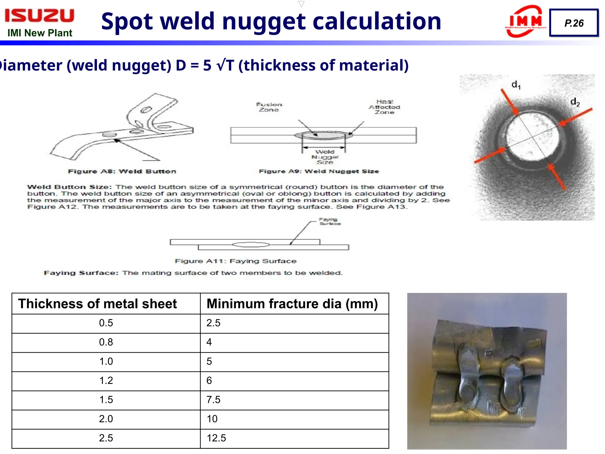
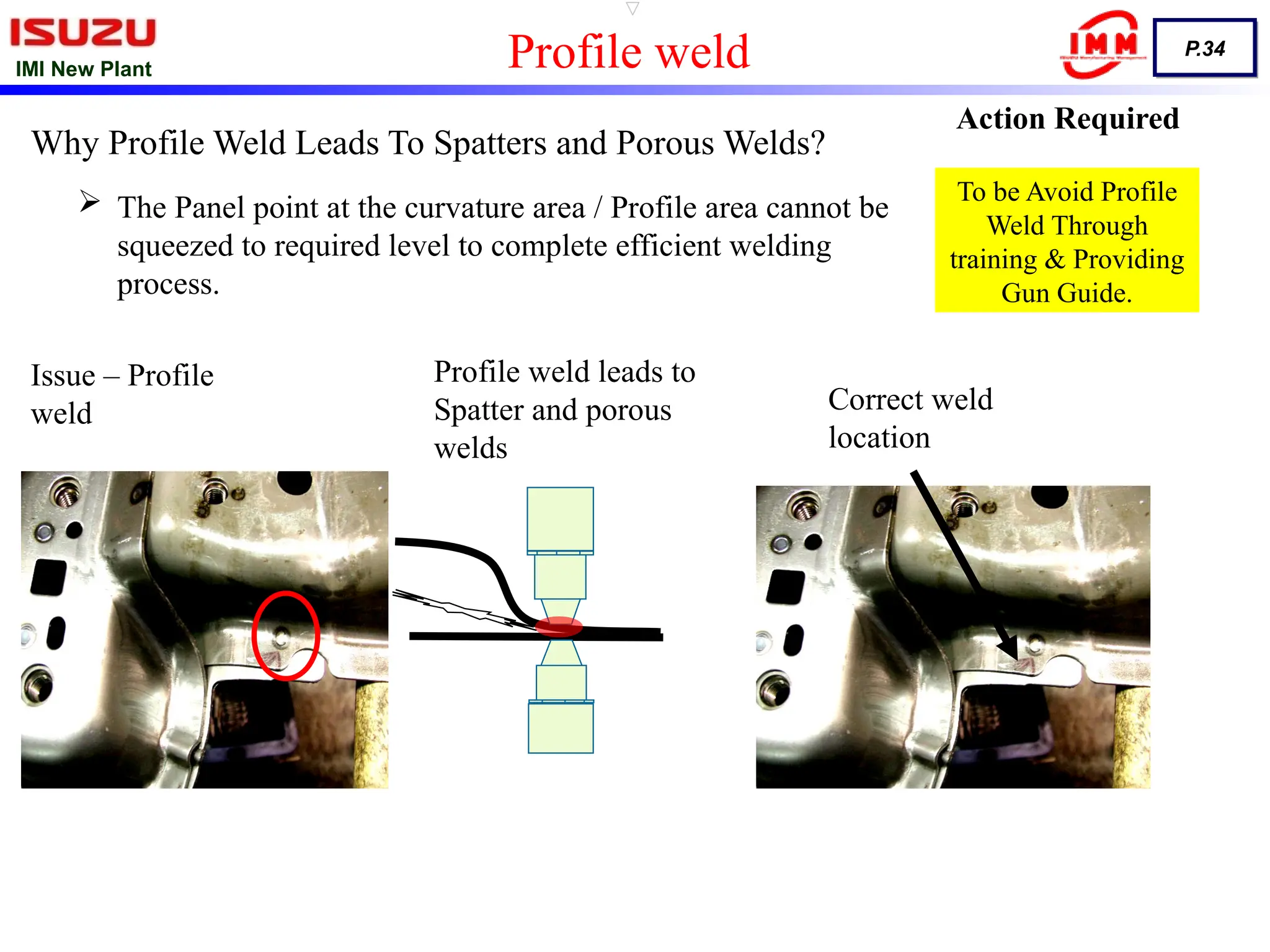
IMI New Plant
P.1
Basics of Welding
Spot welding
(resistance welding)
Arc/co2 (MIG/MAG)
IMI New Plant
P.2
What is welding process?
 Welding joins different metals/alloys with a number of processes, in which heat is
supplied either electrically or by fuel(primarily gas). Welding is done by
application of heat or both heat and pressure. The most essential requirements is
Heat. Pressure may be employed, but this is not in many processes essential.
 The welding processes depends on many factors depending on the type.
 The temperature at which welding is done, should be more than the melting point
of the work piece to be welded.
 Welding is the process of permanently joining two or more metal parts, by melting
both materials. The molten materials quickly cool, and the two metals are
permanently bonded.
IMI New Plant
P.3
Gas
Welding
Arc
Welding
Resistance
Welding
Solid State
Welding
Thermo-chemical
Welding
Radiant- Energy
Welding
Classification of Welding Processes
Air –
Acetylene
Oxy-
Acetylene
Oxy-
hydrogen
Pressure
gas
Carbon Arc
SMAW
SAW
GTAW
MIG (co2)
Electroslag
Plasma Arc
Spot
Seam
Projection
Flash Butt
Resistance
Butt
High Freq.
Resistance
Percussion
Cold
Explosive
Friction
Roll
Diffusion
Forge
Hot
Pressure
Ultrasonic
Welding
Thermite Welding
Atomic Hydrogen
Welding
Electron Beam
Welding
Laser Beam
Welding
IMI New Plant
P.4
S.No Welding Country Discoverer
1 Gas Welding
England (1836)
Acetylene Usage
Edmund Davy
2
Arc Welding
England (1800) Sir Humphry Davy
France (1881-Cabot Labs) Auguste De Meritens
US (1890) Detroit C/L.Coffin (Metal Electrode)
Sweden (1900) Oscar Kjellberg (Coated Electrode)
Great Britain(1907) Strohmenger (Coated Electrode)
3 Stud Welding England Martin
4 Resistance Welding US (1885-1900) Prof. Elihu Thomson
History of welding
IMI New Plant
P.5
Spot Welding
IMI New Plant
P.6
Definition of Resistance Welding :
 Resistance welding is a fusion welding process in which
combination of metals is produced at the faying surfaces by the
heat generated at the joint by the resistance of the work to the
flow of electricity.
 Force is applied before, during, and after the application of current
to prevent arcing at the work piece.
 Melting occurs at the faying surfaces during welding.
Resistance welding depends on three factors:
– Time of current flow (T).
– Resistance of the conductor (R)
– Amperage (I).
Heat generation is expressed as
Q = I2
R T, Q = Heat generated.
IMI New Plant
P.7
Servo robotic guns
integrated trans
guns
portable guns
robotic guns
fixture guns
IMI New Plant
P.8
Hange
r
Trigger
switch
Trigger
cable
Aid cable
Fitting
Arm
(yoke)
Moving
piston
Shank
Adapto
r Cylinde
r
Retract lever
IMI New Plant
P.9
AC controllers
DC controllers controllers integrated trans
AC transformer for
robotic guns
AC transformer for
potable guns
DC integrated transformer
for robotic guns
Timer & transformer control
IMI New Plant
P.10
Cap tip shanks
adaptors
One piece Cap tip holders Insert electrodes
Consumable parts
IMI New Plant
P.11
Kick less cable Aid cable Air cooled jumper
cables
Hose connectors
Tip dresser
(robotic)
shunts
IMI New Plant
P.12
There are two factors or variables mainly responsible for resistance welding are :-
1. The generation of Heat at the place where two pieces are to be joined.
2. The application of pressure at the place where a weld joint is to be formed.
Heat
The heat, H, for electrical resistance welding is generated by passing a large electrical
current through two pieces of metal that are touching each other.
H α I2RT
where H is the heat generate Indicate In joules,
I is the current in root mean square amperes,
R is the resistance in ohms,
T is the time (from fraction of a second to a few seconds) of
current flow through the pieces to be welded
Fundamental of spot welding process
IMI New Plant
P.13
The temperature in resistance welding is regulated by controlling the magnitude and timing of
the welding current. Enough welding current is required to heat the metal pieces being welded
to their plastic state.
The current is obtained from a step down transformer. The magnitude of current can be
Controlled through taps on the primary of the transformer
Current, I
Resistance, R
The total resistance of the system between the electrodes consists of
(i) The resistance of the workpieceR1.
(ii) The contact resistance between the electrodes and the work, R2,
and(iii) The resistance between the faying surfaces of the two metal
pieces to be welded together, R3.
In order to obtain a sound weld and to avoid overheating of the
welding electrodes, R1 and R2 should be kept as low as possible
with respect to resistance R3.
IMI New Plant
P.14
The Four Steps of Spot Welding
The process of resistance spot welding is made of four steps as shown.
1. Squeeze
2. Weld
3. Hold
4. Off
The time for all these steps are expressed in cycles where one cycle is
equal to 1/50th
of a second (if a 50Hz A/C source is used)
IMI New Plant
P.15
 Squeeze time is the time between the initial application o f the electrode pressure
on the work and the first application of current in making the spot weld. It provides
time for the solenoid actuated head cylinder valve to operate and for the welding
electrode to bring the upper electrode rin contact with the work piece and develop
full electrode force.
 Remember however, that resistance spot welding machines are NOT designed as
force clamps to pull the work pieces together for welding. Spot welders are not
designed as an electrical C clamp. Materials should be in perfect contact before
pressure application.
Squeeze Cycle
1 2 4
3
Only Pressure, No current
Squeezing the work Pieces together
IMI New Plant
P.16
 Weld Time is the interval during which the full welding current is applied.
 Some time this weld step is accompanied with,
1. Pre Heat (to reduce thermal gradient and to melt zinc in galvanized steel)
2. Post Heat (for grain refinement(tempering) on hardenable carbon alloy steel)
 This is when the metals are being heated enough to melt and fuse
together to form what is called as a weld nugget.
Weld Cycle
1 2 4
3
Pressure, Along with current
Current passes thro the electrodes and work pieces.
IMI New Plant
P.17
 Hold time is the interval during which, after the the welding current is
off, the electrode force is held on the work piece until the metal of the
spot weld has solidified.
 If the proper hold time is not given and the electrode force is withdrawn
immediately, then the solidification and fusion process will not happen in
between the metals.
Hold Cycle
1 2 4
3
Only Pressure, No current
Squeezing the work Pieces together to get solidification at the center.
IMI New Plant
P.18
 Off Time is the interval from the end of the hold time until the beginning
of the squeeze time for next cycle. The time needed to retract electrode,
remove, reposition the work piece.
 Normally used for continuous welding(Stitch mode)
Off time
1. Squeeze - Pressure is applied to a lap joint of two pieces of sheet metal
by two opposing cylindrical electrodes.
2. Weld -While the pressure is being applied, the current is turned on to
create the weld.
3. Hold - The current is turned off while pressure continues to be applied.
4. Off -The pressure is released after the weld nugget has formed.
Relook into the Spot Welding Stages
1 2 4
3
1 2 4
3
1 2 4
3
4
IMI New Plant
P.19
Basic Single Impulse
Welding Cycle
Electrode Force
Welding Current
Squeeze Time
Weld Time Hold
Time
Off
Time
Welding Cycle
IMI New Plant
P.20
Welding
Cycle
IMI New Plant
P.21
Application of Spot welding
1. Spot welding vast application in automobile and aircraft industries.
such as for Body Shell, Fuel tank etc.
2. The attachment of braces, brackets, pads or clips to formed sheet
metal parts such as cases, covers, bases or trays is another application
of spot welding.
3. Now a days , spot welding is considered as replacement of riveting.
4. The attachment of braces, brackets, pads or clips to formed sheet
metal parts such as cases, covers, bases or trays is another application
of spot welding.
1. Low cost .
2. High speed of welding.
3. Dependability.
4. More general elimination of warping or distortion of parts.
5. High uniformity of products .
6. No edge preparation is needed.
Advantages
IMI New Plant
P.22
Destructive Test
Weld Control
Teardown
Non destructive Test
Coupon Test Complete Body shell
Ultrasonic testing
Visual checking Pry bar checking
IMI New Plant
P.23
Spot welding defects
Cracks & pinhole Excessive indentation Stuck weld
Burn weld Edge weld Non round weld
Non continuousness
Undersize weld Excess welding
IMI New Plant
P.24
Adobe Acrobat
Document
Spot welding defects
Stuck electrodes Missing weld
Poor appearance
Brittle weld
Sheet metal distortion Interfacial separation
IMI New Plant
P.25
Weld spatters
SPATTER BETWEEN SHEETS
1. HEAD LOWERING
2. ELECTRODE FORCE TOO LOW
3. WELDING CURRENT TOO HIGH
4. WELD TIME TOO LONG
5. ELECTRODE TIP DIAMETER TOO SMALL
6. IMPURITIES ON THE SHEET
EXTERNAL SPATTER ON SHEETS
1. HEAD LOWERING AND SQUEEZE TIME TOO
SHORT
2. CURRENT TOO HIGH IN RELATION TO THE
PRESSURE
3. IMPURITIES ON THE SURFACES
4. UNSUITABLE ELECTRODE MATERIAL
(ELECTRIACL RESISTANCE IS TOO HIGH).
ELECTRODE IMPRESION TOO HIGH.
1. UNSUITABLE ELECTRODE FORCE.
2. WELDING CURRENT HIGH.
3. WELD TIME TOO LONG.
4. ELECTRODE TIP DIAMETER TOO SMALL.
BURNED MATERIAL ON OUTSIDE SURFACES.
1. WELDING CURRENT TOO HIGH..
2. ELECTRODE FORCE TOO LOW
3. HEAD LOWERING AND SQUEEZE TIME TOO SMALL.
4. ELECTRODE TIP DIA TOO SMALL
5. ELECTRODE DESIGN UNSUITABLE
6. ELECTRODE MATERIAL UNSUITABLE
7. POOR COOLING OF ELECTRODE TIPS
8. ELECTRODE TIPS NOT CLEAN
9. WORKPIECE SHEET NOT CLEAN.
IMI New Plant
P.26
Thickness of metal sheet Minimum fracture dia (mm)
0.5 2.5
0.8 4
1.0 5
1.2 6
1.5 7.5
2.0 10
2.5 12.5
Spot weld nugget calculation
Diameter (weld nugget) D = 5 T (thickness of material)
√
IMI New Plant
P.27
• Shunt effects
• Welding splashes
ø6 ø9
• Electrode wear
• Changes in kind and thickness of coating
• Switch between 2 and 3 sheets welding
operations
• Adhesive between the sheets
• Drop and increase in electrode force
Weld disturbance
IMI New Plant
P.28
Bad - Tip dress
Tip Dressing Comparison &Tip Dressing Method
Ok - Tip dress
Use always smooth file.
Place smooth file and twist to
form landing surface.
Ensure the landing surface
roughly about 6mm in
diameter.
LANDING As
per
requirements
TEMPLATE
Tip life gauge
Welding tip Made of CU (copper),ZR (zirconium),CR-
IMI New Plant
P.29
Tip Dressing Method
TIP
FILE
FILE
TIP
STEP
1
STEP
2
STEP 3
SMOOTH FILE
Safety procedures to be followed as per the Job Instruction
IMI New Plant
P.30
Tip Changing Method
IMI New Plant
P.31
Alignment & slippage issue
IMI New Plant
P.32
Gun angle & shunting issue
IMI New Plant
P.33
Gun angle alignment issue
IMI New Plant
P.34
Issue – Profile
weld
Profile weld leads to
Spatter and porous
welds
Correct weld
location
Why Profile Weld Leads To Spatters and Porous Welds?
 The Panel point at the curvature area / Profile area cannot be
squeezed to required level to complete efficient welding
process.
Action Required
To be Avoid Profile
Weld Through
training & Providing
Gun Guide.
Profile weld
IMI New Plant
P.35
 This type of poor spots will not Acceptable.
Samples For Poor Angle / Alignment
IMI New Plant
P.36
Samples For Good Angle / Alignment
Good spots for better quality
IMI New Plant
P.37
TIP DRESS
DRIVE CHECK
TIP MANAGEMENT
TORQUE MANAGEMENT
2MINS INSPECTION
IMI New Plant
P.38
PARAMETERMONITORING
TEAR DOWN
DASH&DASH
SAFETY PATROL
IMI New Plant
P.39
START UP CHECKSHEET
TPM
IMI New Plant
P.40
Quality Issues Vs Possible
Causes
IMI New Plant
P.41
Quality Issues Vs Possible
Causes
IMI New Plant
P.42
Quality Issues Vs Possible
Causes
IMI New Plant
P.43
Quality Issues Vs Possible
Causes
IMI New Plant
P.44
Thank you

resistance_spot_welding_01234567895.pptx

  • 1.
    IMI New Plant P.1 Basicsof Welding Spot welding (resistance welding) Arc/co2 (MIG/MAG)
  • 2.
    IMI New Plant P.2 Whatis welding process?  Welding joins different metals/alloys with a number of processes, in which heat is supplied either electrically or by fuel(primarily gas). Welding is done by application of heat or both heat and pressure. The most essential requirements is Heat. Pressure may be employed, but this is not in many processes essential.  The welding processes depends on many factors depending on the type.  The temperature at which welding is done, should be more than the melting point of the work piece to be welded.  Welding is the process of permanently joining two or more metal parts, by melting both materials. The molten materials quickly cool, and the two metals are permanently bonded.
  • 3.
    IMI New Plant P.3 Gas Welding Arc Welding Resistance Welding SolidState Welding Thermo-chemical Welding Radiant- Energy Welding Classification of Welding Processes Air – Acetylene Oxy- Acetylene Oxy- hydrogen Pressure gas Carbon Arc SMAW SAW GTAW MIG (co2) Electroslag Plasma Arc Spot Seam Projection Flash Butt Resistance Butt High Freq. Resistance Percussion Cold Explosive Friction Roll Diffusion Forge Hot Pressure Ultrasonic Welding Thermite Welding Atomic Hydrogen Welding Electron Beam Welding Laser Beam Welding
  • 4.
    IMI New Plant P.4 S.NoWelding Country Discoverer 1 Gas Welding England (1836) Acetylene Usage Edmund Davy 2 Arc Welding England (1800) Sir Humphry Davy France (1881-Cabot Labs) Auguste De Meritens US (1890) Detroit C/L.Coffin (Metal Electrode) Sweden (1900) Oscar Kjellberg (Coated Electrode) Great Britain(1907) Strohmenger (Coated Electrode) 3 Stud Welding England Martin 4 Resistance Welding US (1885-1900) Prof. Elihu Thomson History of welding
  • 5.
  • 6.
    IMI New Plant P.6 Definitionof Resistance Welding :  Resistance welding is a fusion welding process in which combination of metals is produced at the faying surfaces by the heat generated at the joint by the resistance of the work to the flow of electricity.  Force is applied before, during, and after the application of current to prevent arcing at the work piece.  Melting occurs at the faying surfaces during welding. Resistance welding depends on three factors: – Time of current flow (T). – Resistance of the conductor (R) – Amperage (I). Heat generation is expressed as Q = I2 R T, Q = Heat generated.
  • 7.
    IMI New Plant P.7 Servorobotic guns integrated trans guns portable guns robotic guns fixture guns
  • 8.
    IMI New Plant P.8 Hange r Trigger switch Trigger cable Aidcable Fitting Arm (yoke) Moving piston Shank Adapto r Cylinde r Retract lever
  • 9.
    IMI New Plant P.9 ACcontrollers DC controllers controllers integrated trans AC transformer for robotic guns AC transformer for potable guns DC integrated transformer for robotic guns Timer & transformer control
  • 10.
    IMI New Plant P.10 Captip shanks adaptors One piece Cap tip holders Insert electrodes Consumable parts
  • 11.
    IMI New Plant P.11 Kickless cable Aid cable Air cooled jumper cables Hose connectors Tip dresser (robotic) shunts
  • 12.
    IMI New Plant P.12 Thereare two factors or variables mainly responsible for resistance welding are :- 1. The generation of Heat at the place where two pieces are to be joined. 2. The application of pressure at the place where a weld joint is to be formed. Heat The heat, H, for electrical resistance welding is generated by passing a large electrical current through two pieces of metal that are touching each other. H α I2RT where H is the heat generate Indicate In joules, I is the current in root mean square amperes, R is the resistance in ohms, T is the time (from fraction of a second to a few seconds) of current flow through the pieces to be welded Fundamental of spot welding process
  • 13.
    IMI New Plant P.13 Thetemperature in resistance welding is regulated by controlling the magnitude and timing of the welding current. Enough welding current is required to heat the metal pieces being welded to their plastic state. The current is obtained from a step down transformer. The magnitude of current can be Controlled through taps on the primary of the transformer Current, I Resistance, R The total resistance of the system between the electrodes consists of (i) The resistance of the workpieceR1. (ii) The contact resistance between the electrodes and the work, R2, and(iii) The resistance between the faying surfaces of the two metal pieces to be welded together, R3. In order to obtain a sound weld and to avoid overheating of the welding electrodes, R1 and R2 should be kept as low as possible with respect to resistance R3.
  • 14.
    IMI New Plant P.14 TheFour Steps of Spot Welding The process of resistance spot welding is made of four steps as shown. 1. Squeeze 2. Weld 3. Hold 4. Off The time for all these steps are expressed in cycles where one cycle is equal to 1/50th of a second (if a 50Hz A/C source is used)
  • 15.
    IMI New Plant P.15 Squeeze time is the time between the initial application o f the electrode pressure on the work and the first application of current in making the spot weld. It provides time for the solenoid actuated head cylinder valve to operate and for the welding electrode to bring the upper electrode rin contact with the work piece and develop full electrode force.  Remember however, that resistance spot welding machines are NOT designed as force clamps to pull the work pieces together for welding. Spot welders are not designed as an electrical C clamp. Materials should be in perfect contact before pressure application. Squeeze Cycle 1 2 4 3 Only Pressure, No current Squeezing the work Pieces together
  • 16.
    IMI New Plant P.16 Weld Time is the interval during which the full welding current is applied.  Some time this weld step is accompanied with, 1. Pre Heat (to reduce thermal gradient and to melt zinc in galvanized steel) 2. Post Heat (for grain refinement(tempering) on hardenable carbon alloy steel)  This is when the metals are being heated enough to melt and fuse together to form what is called as a weld nugget. Weld Cycle 1 2 4 3 Pressure, Along with current Current passes thro the electrodes and work pieces.
  • 17.
    IMI New Plant P.17 Hold time is the interval during which, after the the welding current is off, the electrode force is held on the work piece until the metal of the spot weld has solidified.  If the proper hold time is not given and the electrode force is withdrawn immediately, then the solidification and fusion process will not happen in between the metals. Hold Cycle 1 2 4 3 Only Pressure, No current Squeezing the work Pieces together to get solidification at the center.
  • 18.
    IMI New Plant P.18 Off Time is the interval from the end of the hold time until the beginning of the squeeze time for next cycle. The time needed to retract electrode, remove, reposition the work piece.  Normally used for continuous welding(Stitch mode) Off time 1. Squeeze - Pressure is applied to a lap joint of two pieces of sheet metal by two opposing cylindrical electrodes. 2. Weld -While the pressure is being applied, the current is turned on to create the weld. 3. Hold - The current is turned off while pressure continues to be applied. 4. Off -The pressure is released after the weld nugget has formed. Relook into the Spot Welding Stages 1 2 4 3 1 2 4 3 1 2 4 3 4
  • 19.
    IMI New Plant P.19 BasicSingle Impulse Welding Cycle Electrode Force Welding Current Squeeze Time Weld Time Hold Time Off Time Welding Cycle
  • 20.
  • 21.
    IMI New Plant P.21 Applicationof Spot welding 1. Spot welding vast application in automobile and aircraft industries. such as for Body Shell, Fuel tank etc. 2. The attachment of braces, brackets, pads or clips to formed sheet metal parts such as cases, covers, bases or trays is another application of spot welding. 3. Now a days , spot welding is considered as replacement of riveting. 4. The attachment of braces, brackets, pads or clips to formed sheet metal parts such as cases, covers, bases or trays is another application of spot welding. 1. Low cost . 2. High speed of welding. 3. Dependability. 4. More general elimination of warping or distortion of parts. 5. High uniformity of products . 6. No edge preparation is needed. Advantages
  • 22.
    IMI New Plant P.22 DestructiveTest Weld Control Teardown Non destructive Test Coupon Test Complete Body shell Ultrasonic testing Visual checking Pry bar checking
  • 23.
    IMI New Plant P.23 Spotwelding defects Cracks & pinhole Excessive indentation Stuck weld Burn weld Edge weld Non round weld Non continuousness Undersize weld Excess welding
  • 24.
    IMI New Plant P.24 AdobeAcrobat Document Spot welding defects Stuck electrodes Missing weld Poor appearance Brittle weld Sheet metal distortion Interfacial separation
  • 25.
    IMI New Plant P.25 Weldspatters SPATTER BETWEEN SHEETS 1. HEAD LOWERING 2. ELECTRODE FORCE TOO LOW 3. WELDING CURRENT TOO HIGH 4. WELD TIME TOO LONG 5. ELECTRODE TIP DIAMETER TOO SMALL 6. IMPURITIES ON THE SHEET EXTERNAL SPATTER ON SHEETS 1. HEAD LOWERING AND SQUEEZE TIME TOO SHORT 2. CURRENT TOO HIGH IN RELATION TO THE PRESSURE 3. IMPURITIES ON THE SURFACES 4. UNSUITABLE ELECTRODE MATERIAL (ELECTRIACL RESISTANCE IS TOO HIGH). ELECTRODE IMPRESION TOO HIGH. 1. UNSUITABLE ELECTRODE FORCE. 2. WELDING CURRENT HIGH. 3. WELD TIME TOO LONG. 4. ELECTRODE TIP DIAMETER TOO SMALL. BURNED MATERIAL ON OUTSIDE SURFACES. 1. WELDING CURRENT TOO HIGH.. 2. ELECTRODE FORCE TOO LOW 3. HEAD LOWERING AND SQUEEZE TIME TOO SMALL. 4. ELECTRODE TIP DIA TOO SMALL 5. ELECTRODE DESIGN UNSUITABLE 6. ELECTRODE MATERIAL UNSUITABLE 7. POOR COOLING OF ELECTRODE TIPS 8. ELECTRODE TIPS NOT CLEAN 9. WORKPIECE SHEET NOT CLEAN.
  • 26.
    IMI New Plant P.26 Thicknessof metal sheet Minimum fracture dia (mm) 0.5 2.5 0.8 4 1.0 5 1.2 6 1.5 7.5 2.0 10 2.5 12.5 Spot weld nugget calculation Diameter (weld nugget) D = 5 T (thickness of material) √
  • 27.
    IMI New Plant P.27 •Shunt effects • Welding splashes ø6 ø9 • Electrode wear • Changes in kind and thickness of coating • Switch between 2 and 3 sheets welding operations • Adhesive between the sheets • Drop and increase in electrode force Weld disturbance
  • 28.
    IMI New Plant P.28 Bad- Tip dress Tip Dressing Comparison &Tip Dressing Method Ok - Tip dress Use always smooth file. Place smooth file and twist to form landing surface. Ensure the landing surface roughly about 6mm in diameter. LANDING As per requirements TEMPLATE Tip life gauge Welding tip Made of CU (copper),ZR (zirconium),CR-
  • 29.
    IMI New Plant P.29 TipDressing Method TIP FILE FILE TIP STEP 1 STEP 2 STEP 3 SMOOTH FILE Safety procedures to be followed as per the Job Instruction
  • 30.
    IMI New Plant P.30 TipChanging Method
  • 31.
  • 32.
    IMI New Plant P.32 Gunangle & shunting issue
  • 33.
    IMI New Plant P.33 Gunangle alignment issue
  • 34.
    IMI New Plant P.34 Issue– Profile weld Profile weld leads to Spatter and porous welds Correct weld location Why Profile Weld Leads To Spatters and Porous Welds?  The Panel point at the curvature area / Profile area cannot be squeezed to required level to complete efficient welding process. Action Required To be Avoid Profile Weld Through training & Providing Gun Guide. Profile weld
  • 35.
    IMI New Plant P.35 This type of poor spots will not Acceptable. Samples For Poor Angle / Alignment
  • 36.
    IMI New Plant P.36 SamplesFor Good Angle / Alignment Good spots for better quality
  • 37.
    IMI New Plant P.37 TIPDRESS DRIVE CHECK TIP MANAGEMENT TORQUE MANAGEMENT 2MINS INSPECTION
  • 38.
    IMI New Plant P.38 PARAMETERMONITORING TEARDOWN DASH&DASH SAFETY PATROL
  • 39.
    IMI New Plant P.39 STARTUP CHECKSHEET TPM
  • 40.
    IMI New Plant P.40 QualityIssues Vs Possible Causes
  • 41.
    IMI New Plant P.41 QualityIssues Vs Possible Causes
  • 42.
    IMI New Plant P.42 QualityIssues Vs Possible Causes
  • 43.
    IMI New Plant P.43 QualityIssues Vs Possible Causes
  • 44.