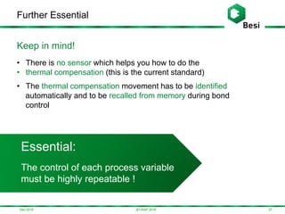
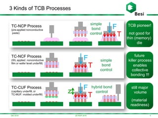
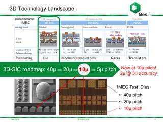
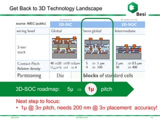
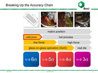
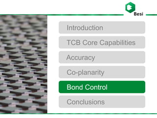
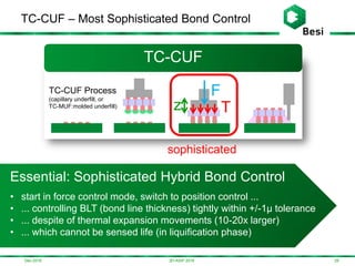
This document summarizes key aspects of thermo compression bonding (TCB) technology from the perspective of a machine vendor. It discusses three core TCB capabilities that are essential for high yield: accuracy, co-planarity, and sophisticated bond control. Maintaining high accuracy during temperature ramping from cold to hot states is critical. Co-planarity must also be maintained during temperature ramping to avoid yield issues. Sophisticated hybrid bond control, as used in the TC-CUF process, tightly controls bond line thickness despite thermal expansion movements.

![0 100 200 300 400 500 600 700 800 900
-2.5
-2
-1.5
-1
-0.5
0
0.5
1
1.5
2
2.5
x[µ],y[µ]
@4305.77.Speck Challenge (17:04:43) [stream]: mean = 0.17/0.02, sigma = 0.16/0.12 @ x/y [µ/µ]
Cpk = 3.88/5.57, Cp = 4.24/5.62 @ x/y [2µ/2µ]
Dec-2016
A Closer Look at the Data
193D-ASIP 2016
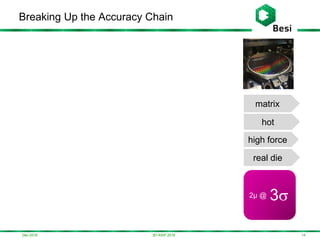
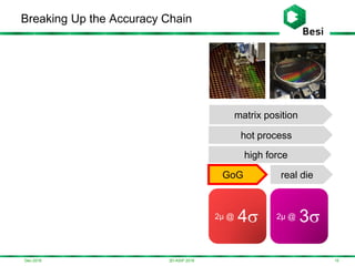
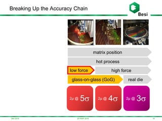
2µ @ 7
required
Single position GoG application
cold (20°C), low force (30N)
2µ @ 11 sigma
achieved!
(+/- 0.55µ)
Matrix GoG application
hot (380°C), high force (250N)
0 200 400 600 800 1000 1200
-2.5
-2
-1.5
-1
-0.5
0
0.5
1
1.5
2
2.5
x[µ],y[µ]
Matrix GoG, T: 100->380°C, 30N [stream]: mean = 0.17/-0, sigma = 0.4/0.4 @ x/y [µ/µ]
Cpk = 1.53/1.68, Cp = 1.67/1.68 @ x/y [2µ/2µ]
2µ @ 4
required
2µ @ 5 sigma
achieved!
(+/- 1.2µ)](https://image.slidesharecdn.com/f0e7e5aa-3ebe-4489-8c30-bc7b0c876c25-161215140611/85/Some-Essentials-of-TCB-19-320.jpg)
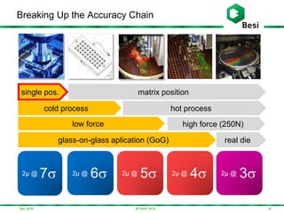
![Accuracy – Essential !
213D-ASIP 2016
Essential - Accuracy
Maintain position accuracy while
ramping from cold to hot state
Dec-2016
single position GoG application
hot (380°C), low force (30N)
2µ @ 5
required weird
behavior !!!
1000 1500 2000 2500 3000 3500 4000 4500
-10
-8
-6
-4
-2
0
2
4
6
8
10
@4305.84.BMC_Test_left_heated_tool_hot (13:51:51)
time
x[µ],y[µ]
Potential Issue
Or: bring accuracy
from bond head down to die
80°C
80°C
80°C->380°C](https://image.slidesharecdn.com/f0e7e5aa-3ebe-4489-8c30-bc7b0c876c25-161215140611/85/Some-Essentials-of-TCB-21-320.jpg)
,T/10[°C](temp.-red),w[µ](pos.-green)
(C) Time t [s] - (selection by: tasks: All Tasks, types: * gantry: L layer: 0)
100
150
200
250
300
Test:
Run 40 repeatable
temperature ramps
from 80°C to 300°C
0 1 2 3 4 5 6 7 8
-4
-2
0
2
4
6
Residues: kinematic: std = NaNµ (Cpk = NaN), thermal: std = 0.69µ (Cpk = 0.48)
#2.56 Tilt 119G-05 (2015-01-29)
-40
-20
0
20
40
60
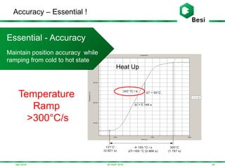
Improper Co-planarity Integrity
Position traces of
4 die corners
Residual analysis out of spec
0 1 2 3 4 5 6 7 8
-4
-2
0
2
4
6
Residues: kinematic: std = 0.03µ (Cpk = 12.29), thermal: std = 0.09µ (Cpk = 3.8)
#2.56 Tilt 119G-05 (2015-01-29)
-40
-20
0
20
40
60
Proper Co-planarity Integrity
Position traces of
4 die corners
Residual analysis in spec +/-1µ
Essential:
Coplanarity Integrity
„Maintain co-planarity during
temperature ramp!“](https://image.slidesharecdn.com/f0e7e5aa-3ebe-4489-8c30-bc7b0c876c25-161215140611/85/Some-Essentials-of-TCB-27-320.jpg)
![Dec-2016
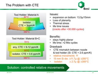
Bond Control for TC-CUF Process
303D-ASIP 2016
z (position)
T (temperature)
F (force)
0 0.5 1 1.5 2 2.5 3 3.5 4 4.5 5 5.5
-20
-10
0
10
20
30
40
50
-200
-100
0
100
200
300
400
500
Temperature[°C]
Bond Control for CUF Process
Force[N],Position[µm]
time [s]
high temperature
ramping rate
200°C/s
dynamic
z-control
during collapse
thermal
compensation
rapid cooling
-100°C/s
• Challenge 1: How do you teach the position control?
• Challenge 2: How do you move from one tool to another?
T (temperature)
F (force)
z (position)
position control.
force
control](https://image.slidesharecdn.com/f0e7e5aa-3ebe-4489-8c30-bc7b0c876c25-161215140611/85/Some-Essentials-of-TCB-30-320.jpg)
![Dec-2016
Enhanced Bond Control for TC-CUF Process
313D-ASIP 2016
0 0.5 1 1.5 2 2.5 3 3.5 4 4.5 5 5.5
-20
-10
0
10
20
30
40
50
-200
-100
0
100
200
300
400
500
Temperature[°C]
Enhanced Bond Control for CUF Process
Force[N],Position[µm]
time [s]
• By distributing bond control over two position axes the
complexity of the bond control is reduced
w (position)
T (temperature)
F (force)
z (position)
thermal
compensation
@ z-position-axis
w-position axis
used for
BLT control
-7µ@2s
responsibility of
process engineer
kinematic
compensation position control.
force
control](https://image.slidesharecdn.com/f0e7e5aa-3ebe-4489-8c30-bc7b0c876c25-161215140611/85/Some-Essentials-of-TCB-31-320.jpg)
![Dec-2016
1) Start with Force Ramp
323D-ASIP 2016
0 0.5 1 1.5 2 2.5 3 3.5 4 4.5 5 5.5
-20
-10
0
10
20
30
40
50
-200
-100
0
100
200
300
400
500
Temperature[°C]
Enhanced Bond Control for CUF Process
Force[N],Position[µm]
time [s]
w (position)
T (temperature)
z (position)
start with
force ramping
-7µ@2s
responsibility of
process engineer
bond head position (w)
reacts with elastic movement)
F (force)](https://image.slidesharecdn.com/f0e7e5aa-3ebe-4489-8c30-bc7b0c876c25-161215140611/85/Some-Essentials-of-TCB-32-320.jpg)
![0 0.5 1 1.5 2 2.5 3 3.5 4 4.5 5 5.5
-20
-10
0
10
20
30
40
50
-200
-100
0
100
200
300
400
500
Temperature[°C]
Enhanced Bond Control for CUF Process
Force[N],Position[µm]
time [s]
Dec-2016
2) Start Temperature Ramping
333D-ASIP 2016
w (position)
T (temperature)
z (position)
-7µ@2s
responsibility of
process engineer
start
temperature
ramping
bond head position (z)
will start moving due to
thermal expansion
Shortly before liquification:
switch from force to position
control (to be prepared for the
soon following force collapse)
hold force
start your compensation for
the thermal expansion](https://image.slidesharecdn.com/f0e7e5aa-3ebe-4489-8c30-bc7b0c876c25-161215140611/85/Some-Essentials-of-TCB-33-320.jpg)
![0 0.5 1 1.5 2 2.5 3 3.5 4 4.5 5 5.5
-20
-10
0
10
20
30
40
50
-200
-100
0
100
200
300
400
500
Temperature[°C]
Enhanced Bond Control for CUF Process
Force[N],Position[µm]
time [s]
Dec-2016
3) Liquification Phase: Hurry up!
343D-ASIP 2016
w (position)
T (temperature)
z (position)
-7µ@2s
responsibility of
process engineer
temperature
exceeds
liquification
threshold
Liquification:
the bump gets
liquid and the
force breaks
down
Luckily you are already in
position mode and you can
control bond head position
for whatever you want!
Hurry up and raise the bond
head position, since by collapse
of the force your compressed
elasticities relax at sudden
don‘t forget: your materials
are thermally expanding!
Compensate with porper
bond head raise movement!
solder climbing
squish
otherwise you get these
nasty results](https://image.slidesharecdn.com/f0e7e5aa-3ebe-4489-8c30-bc7b0c876c25-161215140611/85/Some-Essentials-of-TCB-34-320.jpg)
![0 0.5 1 1.5 2 2.5 3 3.5 4 4.5 5 5.5
-20
-10
0
10
20
30
40
50
-200
-100
0
100
200
300
400
500
Temperature[°C]
Enhanced Bond Control for CUF Process
Force[N],Position[µm]
time [s]
Dec-2016
4) Relax – Solder Joint Formation
353D-ASIP 2016
w (position)
T (temperature)
z (position)
-7µ@2s
Relax!
Adjust bond head position to
form final solder joint height
and never forget:
your materials are still
thermally expanding!
Compensate with porper
bond head raise movement!
responsibility of
process engineer
temperature
is still in a
transient
phase](https://image.slidesharecdn.com/f0e7e5aa-3ebe-4489-8c30-bc7b0c876c25-161215140611/85/Some-Essentials-of-TCB-35-320.jpg)
![0 0.5 1 1.5 2 2.5 3 3.5 4 4.5 5 5.5
-20
-10
0
10
20
30
40
50
-200
-100
0
100
200
300
400
500
Temperature[°C]
Enhanced Bond Control for CUF Process
Force[N],Position[µm]
time [s]
Dec-2016
5) Bring to the End
363D-ASIP 2016
w (position)
T (temperature)
z (position)
-7µ@2s
Hold your solder joint thickness!
Especially during solidification
phase, otherwise you will
impact your solder joint strength
And never forget:
your materials are still
thermally expanding, later
on shrinking!
Compensate with porper
bond head movement!
run the rest of
your thermal profile.
solder joints are still
liquid until
solidification](https://image.slidesharecdn.com/f0e7e5aa-3ebe-4489-8c30-bc7b0c876c25-161215140611/85/Some-Essentials-of-TCB-36-320.jpg)