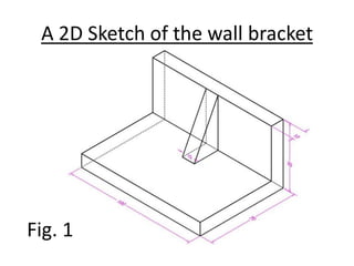
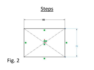
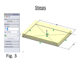
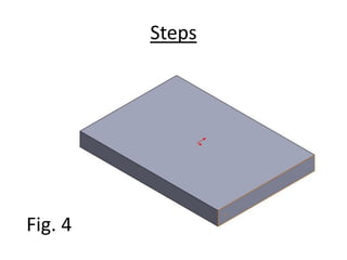
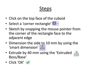
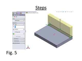
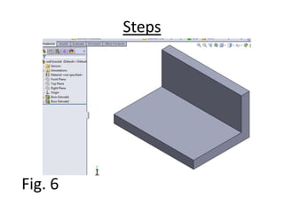
SlideShare a Scribd company logo
SolidWorks Simple Mini Guide
Contents
• Launching the SolidWorks environment
• Drawing a simple wall bracket using:
– Sketch
– Extrude Boss/Base tool
– Rib tool
• Conclusion
Launching the SolidWorks environment
and creating a new environment
• Double-click on the solidworks icon on the
desktop to launch the solidworks then:
i. Click new then choose the part option to
start a new single part drawing.
ii. Or choose the assembly option to assemble
already created parts.
iii. Click ‘OK’
Drawing a simple wall bracket
When drawing on a 3 D environment, there are
usually several ways of realizing a model. This is
due to our different ways of picturing images.
This reason explains why different times are
spent on same drawing, using different
concepts.
A 2D Sketch of the wall bracket
Fig. 1
Steps
• Select ‘Top Plane’ from the draw tree at
the left pane of the drawing environment
• Select ‘center rectangle’ from the sketch
option, snap the mouse to the origin and draw a
rectangle
• Note: All dimensions in ‘mm’ already
• Select ‘Smart Dimension’ and pick the
horizontal side, type 100 mm
• Also, pick the vertical side, type 70 mm
• You should see a drawing similar to fig. 2
Steps
Fig. 2
Steps
• Click ‘Features’ to display a number of
possible options
• Click ‘Extruded Boss/Base’ and in the
space provided for dimension, type 10 mm
• Click the ‘OK’ to confirm the dimensions
• You should see a cuboid that looks like fig. 4 as
shown below
Steps
Fig. 3
Steps
Fig. 4
Steps
• Click on the top face of the cuboid
• Select a ‘corner rectangle’
• Sketch by snapping the mouse pointer from
the corner of the rectangle face to the
adjacent edge
• Dimension the side to 10 mm by using the
‘smart dimension’
• Extrude by 40 mm using the ‘Extruded
Boss/Base’
• Click ‘OK’
Steps
Fig. 5
Steps
Fig. 6
Creating a rib on the wall bracket
• Select the right plane of the model
• Click on ‘Normal To’. This enables the
plane to face you.
• Select a line and draw from the top edge of
the drawing as shown in fig. 7
• Select isometric on the top of the menu to
give a 3D view of the model.
• Dimension the vertical edge with the end of
the drawn line as 20 mm
Steps
Fig. 7
Steps
Fig. 8
Steps
• From the ‘Features’ option, click rib
• On the left pane, a rib menu dialog shows,
make the thickness ‘both sides’ keeping it to
10 mm
• Change the ‘Extrusion direction’ and check
‘Flip material side’ as appropriate
• Click ‘OK’
• The result should look like fig. 9 below
Steps
Fig. 9
Conclusion
• Note: This guide is just to give a fore-sight to
SolidWorks environment. The in-depth shall
be taught in class.

More Related Content

What's hot

Bracket Exercise (Inventor)
Bracket Exercise (Inventor)Bracket Exercise (Inventor)
Bracket Exercise (Inventor)
Andrew Aung
 
Roland Primer 3D Scanner
Roland Primer 3D ScannerRoland Primer 3D Scanner
Roland Primer 3D Scanner
NYCCTfab
 
Catia Part06
Catia Part06Catia Part06
Catia Part06
Girish S Murthy
 
Unit Work Planes
Unit Work PlanesUnit Work Planes
Pinion mount
Pinion mountPinion mount
Pinion mount
Andrew Aung
 
11 Steps: How to Make Revolve Arrows in Adobe Illustrator Using 3D Effect
11 Steps: How to Make Revolve Arrows in Adobe Illustrator Using 3D Effect11 Steps: How to Make Revolve Arrows in Adobe Illustrator Using 3D Effect
11 Steps: How to Make Revolve Arrows in Adobe Illustrator Using 3D Effect
ZillionDesigns
 
How to Make a Web 2.0 Play Button in Adobe Illustrator CS6
How to Make a Web 2.0 Play Button in Adobe Illustrator CS6How to Make a Web 2.0 Play Button in Adobe Illustrator CS6
How to Make a Web 2.0 Play Button in Adobe Illustrator CS6
ZillionDesigns
 
Catia Part05
Catia Part05Catia Part05
Catia Part05
Girish S Murthy
 
Vice Grip Soldiworks Project
Vice Grip Soldiworks ProjectVice Grip Soldiworks Project
Vice Grip Soldiworks ProjectMichael Lagalle
 
Assembling the MugTree (Using Inventor10)
Assembling the MugTree (Using Inventor10)Assembling the MugTree (Using Inventor10)
Assembling the MugTree (Using Inventor10)
krysia
 
Lesson revolve
Lesson revolveLesson revolve
Lesson revolveMr_Burns
 
Lesson loft
Lesson loftLesson loft
Lesson loft
Mr_Burns
 
Catia Part07
Catia Part07Catia Part07
Catia Part07
Girish S Murthy
 
Waffle Structure
Waffle StructureWaffle Structure
Waffle StructureNYCCTfab
 
Molds design in solid works
Molds design in solid worksMolds design in solid works
Molds design in solid works
Long Nguyen
 
Silicone Mold Primer
Silicone Mold PrimerSilicone Mold Primer
Silicone Mold Primer
NYCCTfab
 
3D exercise by gonzalochris
3D exercise by gonzalochris3D exercise by gonzalochris
3D exercise by gonzalochrisChris Gonzalo
 

What's hot (20)

Bracket Exercise (Inventor)
Bracket Exercise (Inventor)Bracket Exercise (Inventor)
Bracket Exercise (Inventor)
 
Roland Primer 3D Scanner
Roland Primer 3D ScannerRoland Primer 3D Scanner
Roland Primer 3D Scanner
 
Catia Part06
Catia Part06Catia Part06
Catia Part06
 
Unit Work Planes
Unit Work PlanesUnit Work Planes
Unit Work Planes
 
Catia Part02
Catia Part02Catia Part02
Catia Part02
 
Pinion mount
Pinion mountPinion mount
Pinion mount
 
11 Steps: How to Make Revolve Arrows in Adobe Illustrator Using 3D Effect
11 Steps: How to Make Revolve Arrows in Adobe Illustrator Using 3D Effect11 Steps: How to Make Revolve Arrows in Adobe Illustrator Using 3D Effect
11 Steps: How to Make Revolve Arrows in Adobe Illustrator Using 3D Effect
 
ViceGripFem
ViceGripFemViceGripFem
ViceGripFem
 
How to Make a Web 2.0 Play Button in Adobe Illustrator CS6
How to Make a Web 2.0 Play Button in Adobe Illustrator CS6How to Make a Web 2.0 Play Button in Adobe Illustrator CS6
How to Make a Web 2.0 Play Button in Adobe Illustrator CS6
 
Catia Part05
Catia Part05Catia Part05
Catia Part05
 
Vice Grip Soldiworks Project
Vice Grip Soldiworks ProjectVice Grip Soldiworks Project
Vice Grip Soldiworks Project
 
Assembling the MugTree (Using Inventor10)
Assembling the MugTree (Using Inventor10)Assembling the MugTree (Using Inventor10)
Assembling the MugTree (Using Inventor10)
 
Lesson revolve
Lesson revolveLesson revolve
Lesson revolve
 
Surface machining
Surface machiningSurface machining
Surface machining
 
Lesson loft
Lesson loftLesson loft
Lesson loft
 
Catia Part07
Catia Part07Catia Part07
Catia Part07
 
Waffle Structure
Waffle StructureWaffle Structure
Waffle Structure
 
Molds design in solid works
Molds design in solid worksMolds design in solid works
Molds design in solid works
 
Silicone Mold Primer
Silicone Mold PrimerSilicone Mold Primer
Silicone Mold Primer
 
3D exercise by gonzalochris
3D exercise by gonzalochris3D exercise by gonzalochris
3D exercise by gonzalochris
 

Similar to SolidWorks mini guide

Inventor notes[1]
Inventor notes[1]Inventor notes[1]
Inventor notes[1]
dedet wahyudi
 
Inventor notes
Inventor notesInventor notes
Inventor notes
Mardhieyah Jamaluddin
 
Using AutoDesk Inventor to create a Trinket box
Using AutoDesk Inventor to create a Trinket boxUsing AutoDesk Inventor to create a Trinket box
Using AutoDesk Inventor to create a Trinket box
krysia
 
Sheet metal design in Solid Edge.docx
Sheet metal design in Solid Edge.docxSheet metal design in Solid Edge.docx
Sheet metal design in Solid Edge.docx
Somashekar S.M
 
Intro to Inventor with MugTree
Intro to Inventor with MugTreeIntro to Inventor with MugTree
Intro to Inventor with MugTree
krysia
 
Solidworks apple mouse Design
Solidworks apple mouse DesignSolidworks apple mouse Design
Solidworks apple mouse Design
Ra'uf Tailony
 
How To Use Sketchup
How To Use SketchupHow To Use Sketchup
How To Use Sketchup
johnysteve
 
Sculpted skateboard fusion 360 rev2
Sculpted skateboard fusion 360 rev2Sculpted skateboard fusion 360 rev2
Sculpted skateboard fusion 360 rev2
dsp39
 
Model and texture a photorealistic usb cable with maya and mental ray
Model and texture a photorealistic usb cable with maya and mental rayModel and texture a photorealistic usb cable with maya and mental ray
Model and texture a photorealistic usb cable with maya and mental ray
Sandra Montoya
 
Workshop2 creep-geo
Workshop2 creep-geoWorkshop2 creep-geo
Workshop2 creep-geo
mmd110
 
Fluid Mechanics Project Assignment (Total 15)  Due Dates  .docx
Fluid Mechanics Project Assignment (Total 15)  Due Dates  .docxFluid Mechanics Project Assignment (Total 15)  Due Dates  .docx
Fluid Mechanics Project Assignment (Total 15)  Due Dates  .docx
bryanwest16882
 
Cad cam lab 2016 2017
Cad cam lab 2016 2017Cad cam lab 2016 2017
Cad cam lab 2016 2017
mohammed faizal
 
Pscs6 ch07 ppt
Pscs6 ch07 pptPscs6 ch07 ppt
Pscs6 ch07 ppt
cpashke
 
Sketchup basic course by Eng. Khalid A. Mter
Sketchup basic course by Eng. Khalid A. MterSketchup basic course by Eng. Khalid A. Mter
Sketchup basic course by Eng. Khalid A. Mter
khalid mter
 
Chuck close inspired portraits instructions
Chuck close inspired portraits instructionsChuck close inspired portraits instructions
Chuck close inspired portraits instructions
Natalie Hurd
 
Finite Element Simulation with Ansys Workbench 14
Finite Element Simulation with Ansys Workbench 14Finite Element Simulation with Ansys Workbench 14
Finite Element Simulation with Ansys Workbench 14
Prem Prakash Pandey
 

Similar to SolidWorks mini guide (20)

Inventor notes[1]
Inventor notes[1]Inventor notes[1]
Inventor notes[1]
 
Inventor notes
Inventor notesInventor notes
Inventor notes
 
Rma w2 d2
Rma   w2 d2Rma   w2 d2
Rma w2 d2
 
Using AutoDesk Inventor to create a Trinket box
Using AutoDesk Inventor to create a Trinket boxUsing AutoDesk Inventor to create a Trinket box
Using AutoDesk Inventor to create a Trinket box
 
Sheet metal design in Solid Edge.docx
Sheet metal design in Solid Edge.docxSheet metal design in Solid Edge.docx
Sheet metal design in Solid Edge.docx
 
Chapter07
Chapter07Chapter07
Chapter07
 
Intro to Inventor with MugTree
Intro to Inventor with MugTreeIntro to Inventor with MugTree
Intro to Inventor with MugTree
 
Solidworks apple mouse Design
Solidworks apple mouse DesignSolidworks apple mouse Design
Solidworks apple mouse Design
 
How To Use Sketchup
How To Use SketchupHow To Use Sketchup
How To Use Sketchup
 
Sculpted skateboard fusion 360 rev2
Sculpted skateboard fusion 360 rev2Sculpted skateboard fusion 360 rev2
Sculpted skateboard fusion 360 rev2
 
Model and texture a photorealistic usb cable with maya and mental ray
Model and texture a photorealistic usb cable with maya and mental rayModel and texture a photorealistic usb cable with maya and mental ray
Model and texture a photorealistic usb cable with maya and mental ray
 
Workshop2 creep-geo
Workshop2 creep-geoWorkshop2 creep-geo
Workshop2 creep-geo
 
Ig proe-wf-5.0
Ig proe-wf-5.0Ig proe-wf-5.0
Ig proe-wf-5.0
 
Ig proe-wf-5.0
Ig proe-wf-5.0Ig proe-wf-5.0
Ig proe-wf-5.0
 
Fluid Mechanics Project Assignment (Total 15)  Due Dates  .docx
Fluid Mechanics Project Assignment (Total 15)  Due Dates  .docxFluid Mechanics Project Assignment (Total 15)  Due Dates  .docx
Fluid Mechanics Project Assignment (Total 15)  Due Dates  .docx
 
Cad cam lab 2016 2017
Cad cam lab 2016 2017Cad cam lab 2016 2017
Cad cam lab 2016 2017
 
Pscs6 ch07 ppt
Pscs6 ch07 pptPscs6 ch07 ppt
Pscs6 ch07 ppt
 
Sketchup basic course by Eng. Khalid A. Mter
Sketchup basic course by Eng. Khalid A. MterSketchup basic course by Eng. Khalid A. Mter
Sketchup basic course by Eng. Khalid A. Mter
 
Chuck close inspired portraits instructions
Chuck close inspired portraits instructionsChuck close inspired portraits instructions
Chuck close inspired portraits instructions
 
Finite Element Simulation with Ansys Workbench 14
Finite Element Simulation with Ansys Workbench 14Finite Element Simulation with Ansys Workbench 14
Finite Element Simulation with Ansys Workbench 14
 

SolidWorks mini guide

  • 2. Contents • Launching the SolidWorks environment • Drawing a simple wall bracket using: – Sketch – Extrude Boss/Base tool – Rib tool • Conclusion
  • 3. Launching the SolidWorks environment and creating a new environment • Double-click on the solidworks icon on the desktop to launch the solidworks then: i. Click new then choose the part option to start a new single part drawing. ii. Or choose the assembly option to assemble already created parts. iii. Click ‘OK’
  • 4. Drawing a simple wall bracket When drawing on a 3 D environment, there are usually several ways of realizing a model. This is due to our different ways of picturing images. This reason explains why different times are spent on same drawing, using different concepts.
  • 5. A 2D Sketch of the wall bracket Fig. 1
  • 6. Steps • Select ‘Top Plane’ from the draw tree at the left pane of the drawing environment • Select ‘center rectangle’ from the sketch option, snap the mouse to the origin and draw a rectangle • Note: All dimensions in ‘mm’ already • Select ‘Smart Dimension’ and pick the horizontal side, type 100 mm • Also, pick the vertical side, type 70 mm • You should see a drawing similar to fig. 2
  • 8. Steps • Click ‘Features’ to display a number of possible options • Click ‘Extruded Boss/Base’ and in the space provided for dimension, type 10 mm • Click the ‘OK’ to confirm the dimensions • You should see a cuboid that looks like fig. 4 as shown below
  • 11. Steps • Click on the top face of the cuboid • Select a ‘corner rectangle’ • Sketch by snapping the mouse pointer from the corner of the rectangle face to the adjacent edge • Dimension the side to 10 mm by using the ‘smart dimension’ • Extrude by 40 mm using the ‘Extruded Boss/Base’ • Click ‘OK’
  • 14. Creating a rib on the wall bracket • Select the right plane of the model • Click on ‘Normal To’. This enables the plane to face you. • Select a line and draw from the top edge of the drawing as shown in fig. 7 • Select isometric on the top of the menu to give a 3D view of the model. • Dimension the vertical edge with the end of the drawn line as 20 mm
  • 17. Steps • From the ‘Features’ option, click rib • On the left pane, a rib menu dialog shows, make the thickness ‘both sides’ keeping it to 10 mm • Change the ‘Extrusion direction’ and check ‘Flip material side’ as appropriate • Click ‘OK’ • The result should look like fig. 9 below
  • 19. Conclusion • Note: This guide is just to give a fore-sight to SolidWorks environment. The in-depth shall be taught in class.