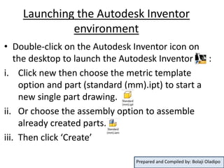
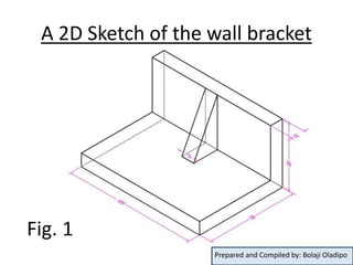
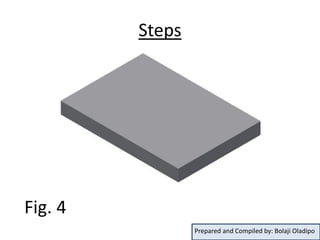
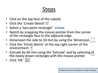
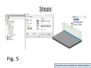
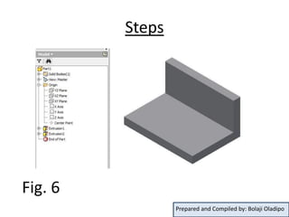
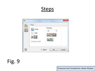
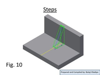
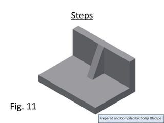
Autodesk Inventor Simple mini guide
Prepared and Compiled by: Bolaji Oladipo
Contents
• Launching the Autodesk Inventor environment
and creating a new document
• Drawing a simple wall bracket
– Sketch
– Extrude Boss/Base tool
– Rib tool
• Conclusion
Prepared and Compiled by: Bolaji Oladipo
Launching the Autodesk Inventor
environment
• Double-click on the Autodesk Inventor icon on
the desktop to launch the Autodesk Inventor :
i. Click new then choose the metric template
option and part (standard (mm).ipt) to start a
new single part drawing.
ii. Or choose the assembly option to assemble
already created parts.
iii. Then click ‘Create’
Prepared and Compiled by: Bolaji Oladipo
Drawing a simple wall bracket
When drawing on a 3 D environment, there are
usually several ways of realizing a model. This is
due to our different ways of picturing images.
This reason explains why different times are
spent on same drawing, using different
concepts.
Prepared and Compiled by: Bolaji Oladipo
A 2D Sketch of the wall bracket
Fig. 1
Prepared and Compiled by: Bolaji Oladipo
Steps
• From the left pane draw tree, click the ‘origin’ to
view the various planes available
• From the various planes displayed, select the ‘xy
plane’
• From the top ribbon menu bar, select ‘3D model’
• Select the ‘sketch’ option
• A four cardinal point appears with a center (the
origin)
Prepared and Compiled by: Bolaji Oladipo
Steps
• Select ‘center rectangle’ from the
sketch option, snap the mouse to the origin
and draw a rectangle
• Note: All dimensions in ‘mm’ already
• Select ‘Dimension’ and pick the horizontal
side, type 100 mm and press the enter key
• Also, pick the vertical side, type 70 mm and
press the enter key
• You should see a drawing similar to fig. 2
Prepared and Compiled by: Bolaji Oladipo
Steps
Fig. 2
Prepared and Compiled by: Bolaji Oladipo
Steps
• Click the ‘Finish Sketch’ at the top right corner
of the environment.
• Click ‘Extrude’ from the ‘3D model’ ribbon
and in the space provided for dimension, type
10 mm
• Click the ‘OK’ to confirm the dimension
• You should see a cuboid that looks like fig. 4 as
shown below
Prepared and Compiled by: Bolaji Oladipo
Steps
Fig. 3
Prepared and Compiled by: Bolaji Oladipo
Steps
Fig. 4
Prepared and Compiled by: Bolaji Oladipo
Steps
• Click on the top face of the cuboid
• Click the ‘Create Sketch’
• Select a ‘two point rectangle’
• Sketch by snapping the mouse pointer from the corner
of the rectangle face to the adjacent edge
• Dimension the side to 10 mm by using the ‘dimension’
• Click the ‘Finish Sketch’ at the top right corner of the
environment.
• Extrude by 40 mm using the ‘Extrude’ and by selecting
the newly drawn rectangle with the mouse pointer
• Click ‘OK’
Prepared and Compiled by: Bolaji Oladipo
Steps
Fig. 5
Prepared and Compiled by: Bolaji Oladipo
Steps
Fig. 6
Prepared and Compiled by: Bolaji Oladipo
Creating a rib on the wall bracket
• Select the ‘yz plane’ of the model from the drawing
tree
• Click on ‘Right’ from the view cube at the right of
the environment. This enables the plane to face you.
• Select a line and draw from the top edge of the model
as shown in fig. 7
• Constrain the start of the line to the top edge of the
model by:
– Click on the coincident constraint
– Click on the start of the line
– Click on the top edge of the model
Prepared and Compiled by: Bolaji Oladipo
Steps
• Also, by using the same coincident constraint:
– Click on the coincident constraint,
– Click on the end of the line
– Click on the corresponding horizontal edge of the
model as shown in fig. 7
• Click on ‘home’ from the view cube at the right of
the environment to give a 3D view of the model.
• Dimension the vertical edge with the end of the
drawn line as 20 mm
Prepared and Compiled by: Bolaji Oladipo
Steps
Fig. 7
Prepared and Compiled by: Bolaji Oladipo
Steps
Fig. 8
Prepared and Compiled by: Bolaji Oladipo
Steps
• From the ‘3D Model’ option, click ‘rib’
• On the screen, a rib menu dialog box pops up,
make the thickness ‘both sides’ keeping it to 10
mm, click:
– ‘Parallel to sketch plane’
– ‘direction 2’
– ‘to next’
All as appropriate
• Click ‘OK’
• The result should look like fig. 11 below
Prepared and Compiled by: Bolaji Oladipo
Steps
Fig. 9
Prepared and Compiled by: Bolaji Oladipo
Steps
Fig. 10
Prepared and Compiled by: Bolaji Oladipo
Steps
Fig. 11
Prepared and Compiled by: Bolaji Oladipo
Conclusion
• Note: This guide is just to give a fore-sight to
Autodesk Inventor environment. The in-depth
shall be taught in class.
Prepared and Compiled by: Bolaji Oladipo

Autodesk Inventor mini guide upload

  • 1.
    Autodesk Inventor Simplemini guide Prepared and Compiled by: Bolaji Oladipo
  • 2.
    Contents • Launching theAutodesk Inventor environment and creating a new document • Drawing a simple wall bracket – Sketch – Extrude Boss/Base tool – Rib tool • Conclusion Prepared and Compiled by: Bolaji Oladipo
  • 3.
    Launching the AutodeskInventor environment • Double-click on the Autodesk Inventor icon on the desktop to launch the Autodesk Inventor : i. Click new then choose the metric template option and part (standard (mm).ipt) to start a new single part drawing. ii. Or choose the assembly option to assemble already created parts. iii. Then click ‘Create’ Prepared and Compiled by: Bolaji Oladipo
  • 4.
    Drawing a simplewall bracket When drawing on a 3 D environment, there are usually several ways of realizing a model. This is due to our different ways of picturing images. This reason explains why different times are spent on same drawing, using different concepts. Prepared and Compiled by: Bolaji Oladipo
  • 5.
    A 2D Sketchof the wall bracket Fig. 1 Prepared and Compiled by: Bolaji Oladipo
  • 6.
    Steps • From theleft pane draw tree, click the ‘origin’ to view the various planes available • From the various planes displayed, select the ‘xy plane’ • From the top ribbon menu bar, select ‘3D model’ • Select the ‘sketch’ option • A four cardinal point appears with a center (the origin) Prepared and Compiled by: Bolaji Oladipo
  • 7.
    Steps • Select ‘centerrectangle’ from the sketch option, snap the mouse to the origin and draw a rectangle • Note: All dimensions in ‘mm’ already • Select ‘Dimension’ and pick the horizontal side, type 100 mm and press the enter key • Also, pick the vertical side, type 70 mm and press the enter key • You should see a drawing similar to fig. 2 Prepared and Compiled by: Bolaji Oladipo
  • 8.
    Steps Fig. 2 Prepared andCompiled by: Bolaji Oladipo
  • 9.
    Steps • Click the‘Finish Sketch’ at the top right corner of the environment. • Click ‘Extrude’ from the ‘3D model’ ribbon and in the space provided for dimension, type 10 mm • Click the ‘OK’ to confirm the dimension • You should see a cuboid that looks like fig. 4 as shown below Prepared and Compiled by: Bolaji Oladipo
  • 10.
    Steps Fig. 3 Prepared andCompiled by: Bolaji Oladipo
  • 11.
    Steps Fig. 4 Prepared andCompiled by: Bolaji Oladipo
  • 12.
    Steps • Click onthe top face of the cuboid • Click the ‘Create Sketch’ • Select a ‘two point rectangle’ • Sketch by snapping the mouse pointer from the corner of the rectangle face to the adjacent edge • Dimension the side to 10 mm by using the ‘dimension’ • Click the ‘Finish Sketch’ at the top right corner of the environment. • Extrude by 40 mm using the ‘Extrude’ and by selecting the newly drawn rectangle with the mouse pointer • Click ‘OK’ Prepared and Compiled by: Bolaji Oladipo
  • 13.
    Steps Fig. 5 Prepared andCompiled by: Bolaji Oladipo
  • 14.
    Steps Fig. 6 Prepared andCompiled by: Bolaji Oladipo
  • 15.
    Creating a ribon the wall bracket • Select the ‘yz plane’ of the model from the drawing tree • Click on ‘Right’ from the view cube at the right of the environment. This enables the plane to face you. • Select a line and draw from the top edge of the model as shown in fig. 7 • Constrain the start of the line to the top edge of the model by: – Click on the coincident constraint – Click on the start of the line – Click on the top edge of the model Prepared and Compiled by: Bolaji Oladipo
  • 16.
    Steps • Also, byusing the same coincident constraint: – Click on the coincident constraint, – Click on the end of the line – Click on the corresponding horizontal edge of the model as shown in fig. 7 • Click on ‘home’ from the view cube at the right of the environment to give a 3D view of the model. • Dimension the vertical edge with the end of the drawn line as 20 mm Prepared and Compiled by: Bolaji Oladipo
  • 17.
    Steps Fig. 7 Prepared andCompiled by: Bolaji Oladipo
  • 18.
    Steps Fig. 8 Prepared andCompiled by: Bolaji Oladipo
  • 19.
    Steps • From the‘3D Model’ option, click ‘rib’ • On the screen, a rib menu dialog box pops up, make the thickness ‘both sides’ keeping it to 10 mm, click: – ‘Parallel to sketch plane’ – ‘direction 2’ – ‘to next’ All as appropriate • Click ‘OK’ • The result should look like fig. 11 below Prepared and Compiled by: Bolaji Oladipo
  • 20.
    Steps Fig. 9 Prepared andCompiled by: Bolaji Oladipo
  • 21.
    Steps Fig. 10 Prepared andCompiled by: Bolaji Oladipo
  • 22.
    Steps Fig. 11 Prepared andCompiled by: Bolaji Oladipo
  • 23.
    Conclusion • Note: Thisguide is just to give a fore-sight to Autodesk Inventor environment. The in-depth shall be taught in class. Prepared and Compiled by: Bolaji Oladipo