1. Chris Blizzard
EML4535C: Vise Grip Modeling In NX 8.5
Project Goals
The goal of this project was to use the software features of NX 8.5 to construct a 3-D
model of a pair of Vise Grips given in class. Each component of the Vice Grip was created
separately based on the actual measurements of the Vise Grip. Functions such as line and circle
tools were utilized to generate a 2-D sketch of each assembly component. The sketches lay a
foundation to compose more complex 3-D bodily dimensions existing on a part. This is done
using design features like extrude, and revolve. By applying assembly constraints, each
completed solid is assembled to produce the full Vise Grip mechanism. The final goal of the
project will be fabrication of a finite element model of the structure enabling stress analysis to
be conducted. The FEM Analysis is covered in the second half of the report. A 10lb is applied to
the ends of both handles. Displacements along the body are observed along with direct stress
properties.
Background
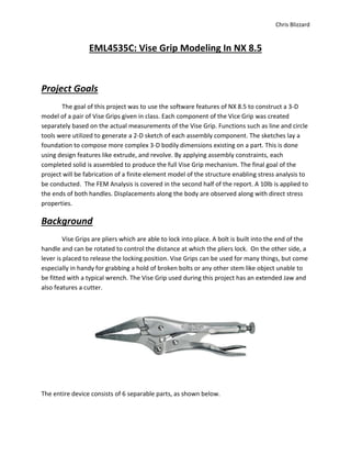
Vise Grips are pliers which are able to lock into place. A bolt is built into the end of the
handle and can be rotated to control the distance at which the pliers lock. On the other side, a
lever is placed to release the locking position. Vise Grips can be used for many things, but come
especially in handy for grabbing a hold of broken bolts or any other stem like object unable to
be fitted with a typical wrench. The Vise Grip used during this project has an extended Jaw and
also features a cutter.
The entire device consists of 6 separable parts, as shown below.
4. Chris Blizzard
All dimensions necessary for modeling were measured and given by the instructor, as well as
supplementary sketches. (See Appendix)
Solid Model
1. Link
Open a new model file and create a new sketch on the XY Plane. Use profile, circle, and fillet
tools to obtain the
sketch.
Extrude Region Boundary curves 3/32 symmetrically
2. Screw
Open a new model file and create a new sketch on the XY Plane. Use insert design feature tab
to create the first cylinder of Height = .23
5. Chris Blizzard
.
Insert another cylinder of height 1.5 on same axis
Add the last cylinder of height 2 again on the same axis
Chamfer edges of solids at equal to the value shown.
6. Chris Blizzard
Use Design feature to thread the center cylinder.
Next create a sketch on the top surface of cylinder one. Create a hexagon and input a value of
.079.
Last use Extrude Boolean subtract to create the cut out.
7. Chris Blizzard
Use Boolean Unite to join the surfaces into one part to obtain the finished sketch
3. Release
Create a new sketch on the XY plane. Use circle tool to create the sketch centered on the axis.
Then use profile tool and fillet to create the rest of the sketch.
8. Chris Blizzard
Finish the first sketch, and then create a new sketch in the XY plane normal to that of the first
sketch.
Next create 6 new datum planes using the “Datum Plane” function. Use the “On Curve” and
“%Arc Length” options in the tool bar to place the Datums, first on the new sketch axis, and
then at 90%, 50%, 30%, 10%, and 0% positions along the original sketch. Be sure to keep the
directions of each Datum the same as well.
9. Chris Blizzard
Create the sketch on Datum 1. “Point on Curve constraint”(POCC) is essential when sketching
along a “Guide Curve”(sketch 1). Be sure each Datum Sketch (1-7) is centered and has a (POCC)
with sketch 1.
Sketch for Datum 2 is identical to that of Datum 1. The next sketch will be on the axis of our
first sketch. Use “offset Curve” to get the desired shape. Use (POCC) to position the sketch
correctly. Create a reference line extending to either end of the sketch in order to use
“Midpoint Constraint”
10. Chris Blizzard
Continue to create sketches on Datum planes according to Dimensions given in the appendix to
get the next figure.
11. Chris Blizzard
Use “Swept” feature. Select Sketch 1 as the guide curve and Add each Datum sketch to the List.
Be sure to click the same direction of each curve. Select cubic interpolation and alignment by
points.
Apply “Edge Blend” to the sections shown. Lastly Extrude the circle, located at sketch origin,
symmetrically using Boolean subtract at a distance of .4 for Final solid (bottom pic)
12. Chris Blizzard
4. Grip
Create a sketch on the XY Plane. Begin by sketching the circle centered on the axis, along with
the other 2 circles found in the sketch. Only the size and position of these circles are important
for this sketch. Use fillets to get the rest of the sketch.
Extrude Sketch 1 5/16” Symmetric Value/Region Boundary Curve
13. Chris Blizzard
Create a Datum plane normal to Sketch one in order to find the correct location for the origin of
the second sketch. Create the sketch then Extrude/ Connected Curves/symmetric
value/Boolean Subtract
Use “Mirror Feature” to equate the other face of the solid to the changes made.
14. Chris Blizzard
Use “Edge Blend” on The back face of the solid, and the corner
The last step of this part is to use Shell method to smooth the figure. Once in the Shell Method
tool bar, under type, choose “remove faces thin shell”. Tangent curves should be selected in the
main toolbar. Use 0.7 for thickness. (Final Part bottom right)
15. Chris Blizzard
5. Jaw
Create a sketch on the XY Plane. Begin the sketch by first creating the circle centered on the
origin. Then create another circle in its general projected position. Use a reference line
connecting the centers of the 2 circles, and another extending from the x-axis, to help position
the part correctly.
Use Profile and Fillet tools to generate the rest of the first sketch.
16. Chris Blizzard
Extrude Sketch 1 Symmetrically at a value of .255/2 using Region Boundary Curve.
Project the curve connected to the “cutter” section of Sketch 1 and convert it to a reference to
draw Sketch 2 (bottom left). Extrude and subtract(bottom right)
The Blade is also tapered at the corner, so another Extrude and Subtraction is shown (bottom
L). The cutter should also be chamfered at 0.05”
17. Chris Blizzard
Project Curve form Sketch 1, and Extrude
To taper the tip of the jaw, create a new sketch on the XZ Plane, then use “Mirror”
18. Chris Blizzard
Now Extrude both curves symmetrically under Region Boundary and choose Boolean Unite.
Unite to Sketch 1 extrusion.
Lastly, Project the bottom fillet from Sketch 1 and create the last hole. Extrude symmetrically,
and unite to form one part.
19. Chris Blizzard
6. Jaw Handle
First Import IGSE File of Jaw.prt. to attain the tip of the jaw(bottom right) which has similar
dimensions to that of the jaw handle(bottom left). Finish sketch, and extrude symmetrically
using region boundary curve and Boolean intersect option.
20. Chris Blizzard
Project the curves from Sketch 1 that would intersect those of the handle. Use these as
reference lines to create Sketch 2 of the jaw handle. Be sure the 2 outer most lines of Sketch 2
are longer than the middle
21. Chris Blizzard
Create Datums along the handle curve at .8(Arc Length), 0.6(Arc Length), 0.3(Arc Length), and
then at 10%, 35%, 55%, 60%. Be sure their directions are all oriented to the same direction.
Create each Sketch in the datums. Utilize the “Intersection Point” constraint to correctly align
each sketch.
22. Chris Blizzard
Use the Swept feature to create the solid. Select each sketch and add it to the “List”. Select the
middle line to be the guide curve. Use cubic interpolation and alignment by points. Also select
connected curves. Be sure to select the same direction for each sketch.
23. Chris Blizzard
Extrude a circle from the screw hole of the jaw handle at a value of 0.3. Select Boolean Unite
and unite the solid with the other. This completes the Jaw Handle.
24. Chris Blizzard
Assembly
Open new assemblies file. Use “Add Component” to bring all 6 parts into the assembly
navigator. Select “Absolute Origin” so to have all parts on one plane.
Apply the Fix constraint to the Jaw Handle.
25. Chris Blizzard
Apply the Fit constraint to the Jaw and Jaw Handle.
Use Touch Align constraint to position the Jaw inside of the Jaw Handle and select “prefer
touch” in the tool bar.
26. Chris Blizzard
Use Fit constraint to align the holes of the Grip and Jaw. Then use the center constrain to
position the jaw between the grip by using the 2 to 2 option and selecting the outer 2 faces of
the grip while selecting the inner surfaces of the Jaw.
Use Touch Align “prefer touch” constrain to align the holes of the Release with those of the
Grip
To kill the DOF for the release apply Bond Constraint for release and Grip
27. Chris Blizzard
Apply Fit constraint for the alignment of the link hole and Grip hole. Then Apply Center
Constraint “2 to 2” option for connector to be positioned between the Grip surfaces.
Use Touch Align constraint then select the infer center axis option to align the center lines of
the Screw and Jaw Handle. Use Distance constraint to control how far the screw dives into the
Jaw Handle.
Hide the Jaw Handle. Apply the Touch Align “2 to2” constraint to the Screw and link. Select the
inner faces of the corner section of the link, while selecting the left and right side edges of the
screw. Use a wire view to select screw edges.
29. Chris Blizzard
Summary
NX proved to be very successful in modeling this project. To my knowledge, there were not any
dimensions unable to be configured. However, this project being a tool with moving parts,
software more capable of modeling movements would be better. As far as modeling/drafting
solid bodies goes, NX makes it very easy to maneuver. Only when it came to assembly did I find
NX was more troublesome with combining movable objects. For the overall purpose of this
assignment, NX is on PAR.
Drafting
30. Chris Blizzard
FE Analysis
1) Overview
The overall idea of the FEM analysis is to subdivide the 3D solid body into simpler parts known as finite
elements. This will enable us to perform stress analysis on the body solvable by Nastran. The main
objective is to perform a static analysis on the Fem model using the actual characteristics of the vice grip
(I.E. material, material thickness, and connecters). This will be done by inserting a specimen in between
the jaws and applying loads to each handle. This part of the report will detail the process of creating a
FEM model and executing an anylisis. The FEM analysis includes Displacements plots and Max stress
plots. Hand calculations are also included to to measure the accuracy of our results
2) Fem
2.1 FE Model
Upload the parts from web courses. Start a new simulation. Go to idealized window. Before starting Fem
use promote tool to select the entire assembly.
31. Chris Blizzard
Create mid surface of these parts by using mid surface by Face Pairs tool.
Use split body to divide the bodies on the ZC plane.
32. Chris Blizzard
Used Curve From bodies/intersect to intersect the Jaw handle with the Jaw.
Use Divide Face
33. Chris Blizzard
Use face merge tool on the handle and the jaw.
Use 2D mesh for Link handle and Grip. Thickness .05 inch, Element Type Cquad4, Type subdivision
Show the mid surfaces of the Jaw and Jaw Handle. Use 3d tetrahedral Mesh using Thickness of .05 inch
and element type of Cquad4
34. Chris Blizzard
Use the insert extrude tool to extrude the cylinder from the handle. Use the screw to apply the correct
vector direction. Make 6 copies each at .05 inch thickness for each copy.
Use insert Element, Copy and Reflect tool. Select the entire body except the Link. Reflect on the x-y
plane (ZC).
35. Chris Blizzard
Use Element Edges pull down to generate element outlines. Select the entire figure and duplicate nodes
at .01 tolerance
Insert a node between the 2 jaw tips. Insert a Cbar element on these nodes.
The 2D meshes have varying thicknesses and are all made of steel. For The Jaw handle use 0.1 inch. The
Link has a thickness of 0.1875 inch. For the Grip change the thickness to 0.07 inch.
For the 3D meshes associated with the jaws, Edit the properties and change their materials to steel.
2.2 FE Assembly
For Joint 1, insert nodes for Grip and Link connection. Show polygons and create 3 nodes, one for each
polygon face.
36. Chris Blizzard
Use 1D connection with element properties type RBE2. Select the center nodes for Source Node. Select
the inner edge of the circles as the target nodes using Feature Edge Nodes Method. Create a collector
for the grip and make another for the link.
Insert a free floating node in the center of the spider of the link. Insert a Cbar that shares the center
node of the 3 spiders of the grip and link.
Insert a Cbush and select the 2 nodes centered in the spider of the link. Edit the stiffness of the Cbush
and add 10e8 for XYZ translation, and XY rotation. Input 0 for Z rotation so to restrict displacement so
you could only rotate in Z.
Edit the 1d manual mesh and enable the CSYS override, Csys type should be absolute.
37. Chris Blizzard
Joint 2: Insert 2 nodes in the center of the top hole of the Jaw handle. Insert another node in between
those two nodes.
Show the Jaw mesh. Use RBE2 and Select the center node as the source node, Use Feature angle nodes
and select the inner surface of the Jaw hole as the target nodes to get a 3d spider mesh.
Create a Cbar element connected by the 3 nodes of the joint.
38. Chris Blizzard
Insert a Cbush at the 2 nodes centered in the 3d spider mesh. Be sure to create a new collector. The 2
Joints should be as shown
Joint 3: Show Jaw Handle polygon and insert 3 nodes, 2 at the center of the hole of the Jaw, and another
between the first 2. Use 1D connector and Use RBE2 and Feature Edge Node method to create a spider
mesh for the Jaw Joint. Use the center nodes for the source node, and the Jaws polygon face for the
target nodes.
Create another 3D spider for the Jaw the same as done before. Hide the 3D mesh to ensure the desired
node is selected. Insert a Cbar element passing through the 3 nodes of the Jaw
39. Chris Blizzard
Be sure to add the Cbar into the correct jaw mesh collector created previously. Show the 3D mesh.
Insert A Cbush element with using the 2 center nodes of the 3D spider of the Jaw. The 3 completed
joints should be as shown
Create 3 nodes for the screw. One at the center of the smaller diameter, another at the center of the
larger diameter, and another between those.Insert a Cbar element for the 3 nodes. Create a new
collector for the smaller diameter section, and then add the larger diameter to the existing collector.
Use 1D collector to add a 3d spider for the screw. Select the center node for the source node. Use No
method and box select the end of the jaw handle for target nodes. Insert another node in the same
position as the one on the inner end of the screw. Use 1D collector and Feature edge Method to create
the spider for the Link. Insert a Cbush element on the 2 center nodes of the Link spider web.
40. Chris Blizzard
Edit the properties of the Cbush 2. Change the XYZ translation to 10e8 and the XYZ rotation to 0. This is
done so it would have the properties of a ball joint despite not actually being a ball joint
Pins
The Dimensions of the Pin CBAR Collectors must be edited.
For Pin Cbar collectors 1, 2 and 4 change the radius to 0.115.
For Cbar collector 3 use a radius of 0.109375 inch.
Cbar 5 is the Nylon Bar (Modified E to 10000 psi) inserted between the Jaws. Radius 0.125
Reasoning for use of different Elements
RBE2 acts like a rigid bonding and allows 0 DOF
Cbar acts as a pin and allows translation in a direction.
Cbush acts as a bearing and allows rotaion in a direction.
2.3 FE Model Check
Element Edge Check
Before After
42. Chris Blizzard
3) Sim
3.1 Gluing
Gluing enables the transfer of loads and moments continuously between different types of meshes. 3
Glues are needed. We will use The Edge to surface gluing method since we need to glue a 2D edge to a
3D surface.
Use the simulation object pulldown to access gluing. Regions must first be created. For the Edge region,
use the Tangent Continuous Edge Method, and select the inner edges of the jaw handle.
For the surfaces, use the Feature Element Method, and select the corresponding surfaces of Jaw that
are in contact with the selected Edge Regions. Now use the Edge to Surface gluing and glue the edges to
their corresponding surfaces.
43. Chris Blizzard
After applying the Gluing
3.2 Loads and support
Constraints
Apply the fixed constraint to the center node of the Nylon Cbar placed between the Jaws. This constraint
will not prevent the vice grip from rotating around the CBAR because the Fixed constraint can grab DOF
(1-6) on the Cbar but cannot transfer DOF (4-6) into the 3D solid.
44. Chris Blizzard
A User defined constraint killing the DOF 3 is needed somewhere on the 3D solid to prevent this rotation
about Z. I chose to apply it at the end of the screw CBAR (Kill DOF 3).
Loads
The loads are applied such that the end points of the handles are squeezed together. The 2 forces
should be of equal 10 lbs of force, and opposite in X-Y direction.
48. Chris Blizzard
Hand
cal Nx(fo6) %error
Bx 24.161 24.615 1.8
By 46.516 46.54 0.05
Gx 24.606 24.615 0.036
Gy 46.525 46.54 0.0322
Cx 26.992 25.455 2.066
Cy 41.232 41.832 1.46
Fx 15.33 34.084 122.34
Fy 42.77 50.18 17.33
F1 52.63 13.485 290.286
F2 52.63 13.485 74.378
Summary
NX proved to be very successful in modeling this project. To my knowledge, there were not any
dimensions unable to be configured. However, this project being a tool with moving parts,
software more capable of modeling movements would be better. As far as modeling/drafting
solid bodies goes, NX makes it very easy to maneuver. Only when it came to assembly did I find
NX was more troublesome with combining movable objects. For the overall purpose of this
assignment, NX is on PAR. Nastran was sufficient in solving the Finite element. The % error
compared to that of the calculated values was not too large besides the F1,F2,Fx,Fy.