The document proposes a solar-powered train system for public transportation. Solar cells would be installed on the rooftops of train coaches to directly charge storage batteries mounted underneath. This system would help address issues like rising fuel costs and shortages of non-renewable energy sources. Developing solar-powered trains is challenging and requires selecting appropriate solar panels, batteries, motors and designing the chassis. If implemented successfully on a large scale, solar-powered trains could help reduce dependence on fossil fuels and make transportation more environmentally friendly.


![6
2.2. History of Photovoltaic Cell
Photovoltaic system converts sun light into electricity. The term "photo" is a
stem from the Greek "photos," which means "light." "Volt" is named for
Alessandro Volta (1745-1827), a pioneer in the study of electricity. "Photo-
voltaic," then, could literally mean "light-electricity." Most commonly known as
"solar cells," PV systems are already an important part of our lives. The simplest
systems power many of the small calculators and wrist watches we use every day.
More complicated systems provide electricity for pumping water, powering
communications equipment, and even lighting our homes and running our
appliances. In a surprising number of cases, PV power is the cheapest form of
electricity performing these tasks.[7]
Photovoltaic cells converts’ lighter energy into electricity into atomic level.
Although first discovered in 1839, the process of producing electric current in
a solid material with the aid of sunlight wasn't truly understood for more than
a hundred years. Through the second half of the 20th century, the science has
been refined and the process has been more fully explained. As a result, the cost of
these devices has put them into the mainstream of modern energy producers. This
was caused in part by advances in the technology, where PV conversion
efficiencies have improved considerably'.
French physicist Edmond Becquerel first described the photovoltaic
(PV) effect in 1839, but it remained a curiosity of science for the next
three quarters of a century. At only 19, Becquerel found that certain materials
would produce small amounts of electric current when exposed to light. The
effect was first studied in solids, such as selenium, by Heinrich Hertz in the
1870s. Soon afterward, selenium PV cells were converting light to electricity at
1% to 2% efficiency. As a result, selenium was quickly adopted in the
emerging field of photography for use in light- measuring devices. Major
steps toward commercializing PV were taken in the 1940s and early 1950s,
when the Czochralski process was developed for producing highly pure
crystalline silicon. In 1954, scientists a t Bell Laboratories depended on the
Czochralski process to develop the first crystalline silicon photovoltaic cell,
which had an efficiency of 4%. The term "photovoltaic" comes from the Greek φῶς
(phōs) meaning "light", and "voltaic", meaning electric, from the name of the Italian
physicist Volta, after whom a unit of electro-motive force, the volt, is named. The term
"photo-voltaic" has been in use in English since 1849.
The photovoltaic effect was first recognized in 1839 by French physicist A. E.
Becquerel. However, it was not until 1883 that the first photovoltaic cell was built, by
Charles Fritts, who coated the semiconductor selenium with an extremely thin layer of
gold to form the junctions. The device was only around 1% efficient. In 1888 Russian](https://image.slidesharecdn.com/1project-150629072141-lva1-app6891/85/Solar-train-by-rohit-6-320.jpg)


![25
Timber sleepers (ties) are of many available timbers, and are often treated with creosote,
copper-chrome-arsenic, or other wood preservative. Pre-stressed concrete sleepers (ties)
are often used where timber is scarce and where tonnage or speeds are high. Steel is used
in some applications.
The track ballast is customarily crushed stone, and the purpose of this is to support the
ties and allow some adjustment of their position, while allowing free drainage.
1. Ballastless track
A disadvantage of traditional track structures is the heavy demand for
maintenance, particularly surfacing (tamping) and lining to restore the desired track
geometry and smoothness of vehicle running. Weakness of the subgrade and drainage
deficiencies also leads to heavy maintenance costs. This can be overcome by using
ballastless track. In its simplest form this consists of a continuous slab of concrete (like a
highway structure) with the rails supported directly on its upper surface (using a resilient
pad).
There are a number of proprietary systems, and variations include a continuous
reinforced concrete slab, or alternatively the use of pre-cast pre-stressed concrete units
lay on a base layer. Many permutations of design have been put forward.
However ballastless track is very expensive in up-front cost and in the case of existing
railroads requires closure of the route for a somewhat long period. Its whole life cost can
be lower because of the great reduction in maintenance requirement. Ballastless track is
usually considered for new very high speed or very high loading routes, in short
extensions that require additional strength (e.g. rail station), or for 25 ocalized
replacement where there are exceptional maintenance difficulties, for example in tunnels.
1.3. Ladder track
Ladder track utilizes sleepers aligned along the same direction as the rails with rung-
like gauge restraining cross members. Both ballasted and ballastless types exist.
1.4.Continuous longitudinally supported track
Early railways (c.1840s) experimented with continuous bearing rail track, in which
the rail was supported along its length, with examples including Brunel’s Baulk road on
the Great Western Railway, as well as use on the Newcastle and North Shields
Railway,[1] on the Lancashire and Yorkshire Railway to a design by John Hawkshaw, and](https://image.slidesharecdn.com/1project-150629072141-lva1-app6891/85/Solar-train-by-rohit-25-320.jpg)
![26
elsewhere.[2] Continuous bearing designs were also promoted by other engineers. The
system was trailed on the Baltimore and Ohio railway in the 1840s, but was found to be
more expensive to maintain than rail with cross ties.
Modern applications of continuously supported track include Balfour Beatty’s
‘Embedded Slab Track’ which uses a rounded rectangular rail profile (BB14072)
embedded in a slip formed (or pre-cast) concrete base (development 2000s), the
‘Embedded Rail Structure’, used in the Netherlands since 1976, initially used a
conventional UIC 54 rail embedded in concrete, later developed (late 1990s) to use a
‘mushroom’ shaped SA42 rail profile; a version for light rail using a rail supported in
an asphalt concrete filled steel trough has also been developed (2002).
2. Chassis
A vehicle frame, also known as its chassis, is the main supporting structure of
a motor vehicle to which all other components are attached, comparable to the skeleton of
an organism.
Until the 1930s, virtually every (motor) vehicle had a structural frame, separate from the
car’s body. This construction design is known as body-on-frame. Since then, nearly all
passenger cars have received unibody construction, meaning their chassis and bodywork have
been integrated into one another. The last UK mass-produced car with a separate chassis was
the Triumph Herald, which was discontinued in 1971. However, nearly all trucks, buses
and pickups continue to use a separate frame as their chassis.
1. Functions
a. To support the vehicle’s mechanical components and body
b. To deal with static and dynamic loads, without undue deflection or distortion.
These include:
Weight of the body, passengers, and cargo loads.
Vertical and torsional twisting transmitted by going over uneven surfaces.
Transverse lateral forces caused by road conditions, side wind, and steering
the vehicle.
Torque from the engine and transmission.
Longitudinal tensile forces from starting and acceleration, as well as
compression from braking.
Sudden impacts from collisions.
3.1.6. Circuit Description](https://image.slidesharecdn.com/1project-150629072141-lva1-app6891/85/Solar-train-by-rohit-26-320.jpg)


![34
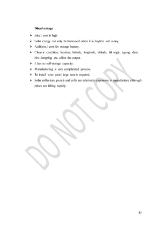
4. Design Procedure
A. Solar Panel
Specification of Solar Panel-
The size of solar panel [inch] =12×8
Output voltage of solar panel [V] = 22.05/ 17.48
Current produced by solar panel [A] = 0.835/ .727
Power of the solar panel [W] = V×I
=10 (pass)
Panel efficiency [%] =15
How to Determine the Efficiency of Solar Panels
Solar panels are relatively simple to maintain, but dirt and improper placement
can significantly decrease their power output. In order to ensure you achieve the
maximum value from this product, you should regularly check the efficiency of your
solar panels. There are four steps to determined the efficiency of solar panel these are
1. Measure the area of your solar panels if you do not already know it.
2. Use a solar meter to measure the maximum solar radiation for the exact
location of your solar panels in kilowatts per meter squared. Essentially, this
measures how much power the sun is bringing to your location--i.e., the
maximum power your solar panels could theoretically provide.
3. Use the volt and amp meter to measure the volts and amps produced by your
solar panels. Multiply volts and amps to calculate the power produced by your
solar panels (P = V x A) in kilowatts. Divide the power by the area of your
solar panels in meters squared.
4. Divide the power output of the solar panel (kW/m^2) by the solar input
measured by the solar meter (kW/m^2). Multiply this number by 100 to get a
percent efficiency. Do not be discouraged if it is low--most solar panels
achieve no more than a maximum of 20 percent efficiency.](https://image.slidesharecdn.com/1project-150629072141-lva1-app6891/85/Solar-train-by-rohit-34-320.jpg)

![36
B. Train Track
Material- Iron
Weight = 5kg
Inner diameter of track [inch] = 24
Outer diameter of track [inch] = 48
Length of track [inch] = 60 + 48](https://image.slidesharecdn.com/1project-150629072141-lva1-app6891/85/Solar-train-by-rohit-36-320.jpg)

![38
C. Chassis
Length of Chassis [inch] = 10
Width of Chassis [inch] = 5
Thickness of chassis [mm] = 1
Material – Iron
Weight = 0.5kg
D. Wheel
Diameter [inch] = 2.5
Width [inch] = 2
Material = Fibre
Weight = 50g
E. Designing of Shaft
Input Voltage of motor =12 volts
Current rating =.717 amp.
Power output of motor = V×I
=12×.717
Power output of motor =8.6 watts.
Power = 2π×N×T
60
8.6 =2 π×60×T
60
T = 1.37 N-m
T = 1370 N-mm
T = π × fs ×d3
16](https://image.slidesharecdn.com/1project-150629072141-lva1-app6891/85/Solar-train-by-rohit-38-320.jpg)


![45
Tesla CEO unveils hyperloop: the solar-powered high-speed train of the future
After much anticipation, Tesla's Elon Musk reveals plans for the hyperloop - a fast,
sustainable and cost-efficient train system without rails yet topped with solar panels and
propelled by both electric motor and air cushion dynamics
An alternative to cars, boats, planes and trains, or the four regular means of travel, the
Hyperloop is a highly anticipated design that comes a year after the electric car company
leader announced his idea for an advanced type of transport. Musk proposed a solution
combining the advantages of air and train travel that could be better than the approved
high-speed rail network in California.
The California High-Speed Rail project, to be completed in 2029, is the first such rail
system in the United States and it is intended to primarily connect travellers between San
Francisco and Los Angeles in less than three hours.
However, in the Hyperloop document, Musk wrote how he was “quite disappointed” with
the planned mass transit. He said, “How could it be that the home of Silicon Valley and
[the Jet Propulsion Laboratory] – doing incredible things like indexing all the world’s
knowledge and putting rovers on Mars – would build a bullet train that is both one of the
most expensive per mile and one of the slowest in the world?”
The Hyperloop is his answer to this dilemma. Designed by engineers from Tesla and
SpaceX, the space transport firm he co-founded, the cutting-edge transportation is an
aboveground steel tube system with aluminium capsules or pods that zoom around
carrying passengers at a speed of 760 miles per hour, or over 1,220 kilometres per hour.
This is faster than a bullet train or the California High-Speed Rail project that has an
estimated rate of 200 miles per hour.
Musk also compared other factors between the Hyperloop and California project, as well
as with other transport options, in the technical section of his design paper. He noted that
while road travel may be inexpensive, it is slow and not so eco-friendly. Air travel, on the
other hand, is expensive but fast, although not environmentally sound. Rail is likewise
expensive, but slow. However, it is the greener option among the three.
Hyperloop, he underscored, is not a give or take of benefits. The design addresses all
requirements of speed, cost and sustainability.
Tesla Model S keeps NHTSA 5-Star rating amid safety probe
Ground – breaking air-rail transport relies on all-electric hybrid system
Tesla not widens as revenue nearly doubles](https://image.slidesharecdn.com/1project-150629072141-lva1-app6891/85/Solar-train-by-rohit-45-320.jpg)


