Downloaded 290 times


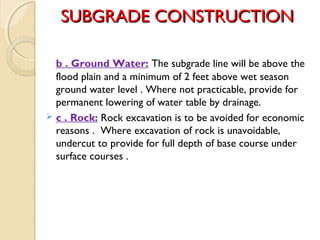
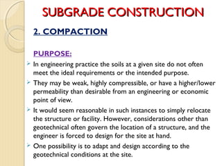


The document discusses pavement materials and field evaluations for geotechnical engineering. It covers various field investigation techniques like drilling, test pits, and geophysical testing methods like seismic and electrical resistivity surveys. Seismic techniques measure wave velocities to evaluate subsurface strata properties. Electrical resistivity uses differences in resistivity between soil/rock layers. Subgrade construction principles are also covered, including establishing grade lines, compaction objectives to improve strength and reduce settlements, and factors that control compaction like soil type, water content, and compactive effort.