Download as PDF, PPTX


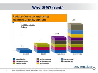


The document discusses the critical importance of design for manufacturing (DFM) in the electronics industry, emphasizing that manufacturing quality can significantly impact product reliability and market competitiveness. It outlines various DFM guidelines, industry standards, and failure analysis techniques essential for optimizing manufacturing processes and ensuring product quality. The workshop aims to educate participants on integrating design and manufacturing effectively to reduce costs and improve manufacturability.


