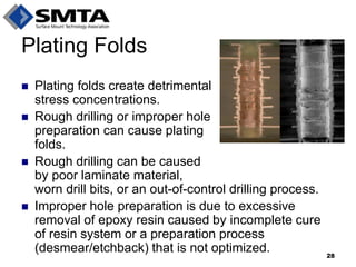
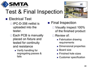
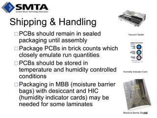
Download as PDF, PPTX

![Why Perform an Onsite Audit?
No industry standard methodology for qualifying PCB suppliers
Standards do exist for lot-based PCB testing and acceptance within the IPC 6010 series
Sourcing follows the “as agreed upon between user and supplier” (AABUS) approach
IPC began discussing this gap in 2008 with a Blue Ribbon Committee
IPC has recently launched a Validation Business Unit with plans to eventually move towards an IPC Qualified Manufacturers List (QML) for suppliers, including PCBs [3]. I
In the meantime, however, onsite audits remain the best approach
13](https://image.slidesharecdn.com/smtai2013pcbbestpracticestulkoff2-140915130219-phpapp02/85/Best-Practices-for-Improving-the-PCB-Supply-Chain-Part-II-13-320.jpg)


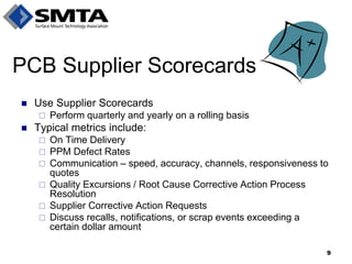
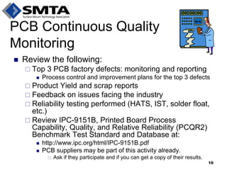
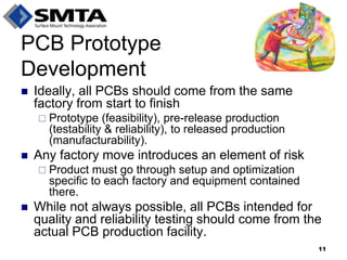
The document outlines best practices for improving the printed circuit board (PCB) supply chain, emphasizing the importance of rigorous supplier selection, qualification, and management processes. It details the formation of a PCB commodity team, supplier tiering strategies, and ongoing relationship management practices to enhance quality and reliability. Additionally, it highlights the necessity of onsite audits and continuous quality monitoring to ensure that PCBs consistently meet specified standards.


![Getting Started with Apache Spark: Big Data Made Simple [Free Meetup]](https://cdn.slidesharecdn.com/ss_thumbnails/apachesparkgettingstarted-260203175547-8361bcc3-thumbnail.jpg?width=640&height=640&fit=bounds)


