Download to read offline
![International Research Journal of Engineering and Technology (IRJET) e-ISSN: 2395-0056
Volume: 09 Issue: 09 | Sep 2022 www.irjet.net p-ISSN: 2395-0072
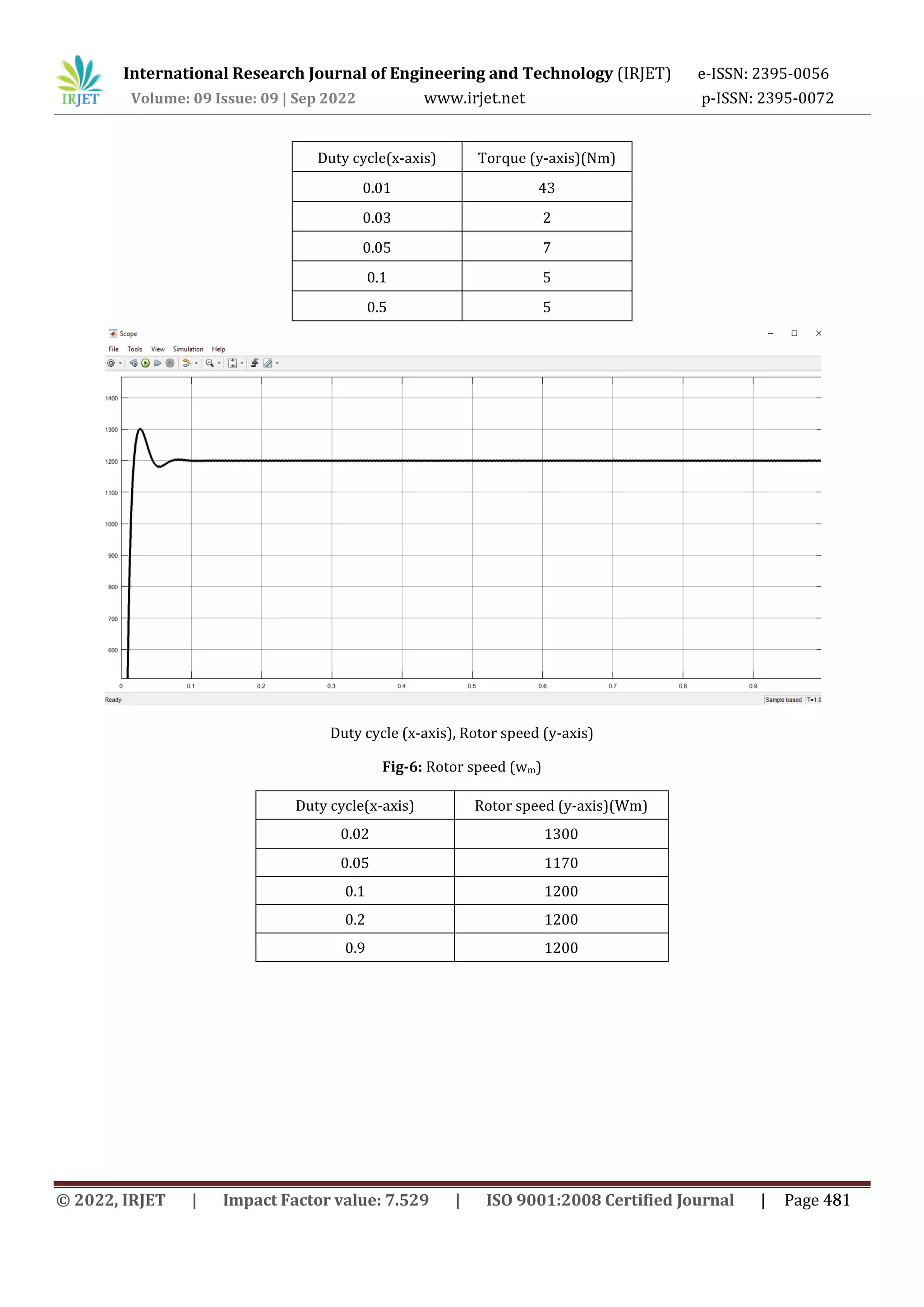
Fig-11: Output of quadratic boost onverter
The load voltage is around 44V which is 3.67 times higher than that of input battery voltage for the duty ratio 0f 33%.
7. CONCLUSION
It has been noted that the input voltage given in both the hardware and software situations is around 12 V. Originally
rated at 50 W, the device's power consumption has decreased to about 32W as a result of loss in the hardware
implementation. In both the hardware implementation and simulation, the output voltage increased by a factor of four to
48 V, which is exactly twice the 24 V target value for a traditional boost converter. In both instances, the switching
frequency was set at 50 kHz, which is recommended for QBC’s with efficiency and high gain. The BLDC motor made to run
by quadratic boost converter using the three phase inverter for the power of 32W.
8. REFERENCES
[1]. B.Chandra Krishna, M.Nageswara Rao “Speed Control of BLDC Motor using Modified Buck Boost Converter” IEEE
Transactions on Power Electronics, vol. 24, no. 5, pp. 1198–1208, May 2019.
[2]. Ashirvad M and Rupesh K C “Quadratic Boost Converter for Grid-Connected MicroInverter” IEEE Trans. Power
Electronics, vol. 30, no. 3, pp. 1488-1498, March. 2019.
[3]. M. Veerachary “Design and Analysis of a Boost Converter” IEEE Transactions on Industrial Electronics, vol. 56, issue 6,
pp. 2203 - 2212, June 2018.
[4]. Kemal Kaya and Yakup Hames “A Quadratic Cascade DC/DC Boost Converter Design” IEEE
Trans. Power Electronic. vol. 18, no. 1, pp.164–172, Jan. 2016.
[5]. Selva Kumar. R, Vignesh.C. J, Gayathri Deivanayaki. V. P. “Design and Comparison of Quadratic Boost Converter with
Boost Converter” IEEE Trans.Ind. Appl., vol. 32, no. 3, pp. 518–525, 2017.
[6]. Mustafa İnci “Design and Analysis of Quadratic Boost Converter with Inductor-Capacitor-Diode Voltage Multiplier
Circuit” IEEE Trans. Ind. Elect.,vol.50, no.5,pp.962– 981,Oct. 2018.
[7]. Angalaeswari S, Deepa.T, Subbulekshmi.D, Krithiga S, Pramit Ghosh, Aniket Kumar, Mutthi Karunanidhi, “Design and
execution of Quadratic Boost Converter (QBC) in Renewabe Energy Synergies” Applied Power Electronics Conference and
Exposition, 2018. APEC 2018. Twenty-Third Annual IEEE, May 2018, pp. 973 - 979.
© 2022, IRJET | Impact Factor value: 7.529 | ISO 9001:2008 Certified Journal | Page 484](https://image.slidesharecdn.com/irjet-v9i983-221031092750-bfb0db54/75/DESIGN-AND-IMPLEMENTATION-OF-QUADRATIC-BOOST-CONVERTER-FOR-APPLICATION-OF-BLDC-MOTOR-7-2048.jpg)
![International Research Journal of Engineering and Technology (IRJET) e-ISSN: 2395-0056
Volume: 09 Issue: 09 | Sep 2022 www.irjet.net p-ISSN: 2395-0072
Based on Coupled inductor with Single Switch and Continuous Input Current” IEEE Transactions on Power Electronics, vol.
29, no. 9, pp.4684-4692, 2019.
[9]. M.S. Aspalli, Farhat Mubeen Munshi, Savitri.L.Medegar “Speed control of BLDC Motor
with Four Switch Three Phase Inverter using Digital Signal Controller” IEEE Trans. Power Electron., vol. 18, no. 1, pp.164–
172, Jan. 2016.
[10] K. I. Hwu, W. C. Tu, "Voltage-boosting converters with hybrid energy pumping," IET Power Electron., vol. 5, no. 2, pp.
185-195,Feb.2017.
[11] Shiyu Zhang, Jianping Xu, Ping Yang, “A single-switch high-gain quadratic boost converter based on voltage-lift-
technique”, Proc. of IEEE IPEC, 2012, pp. 71-75.
[12] K. I. Hwu, Y. T. Yau, “ A KY boost converter,” IEEE Trans. on Power Electron., vol. 25, no. 11, pp. 2699-2703, Nov. 2019.
[8]. S.Alireza Modaberi, Babak Allahverdinejad, Mohamad Reza Banaei, “A Quadratic High Step-up DC-DC Boost Converter
© 2022, IRJET | Impact Factor value: 7.529 | ISO 9001:2008 Certified Journal | Page 485](https://image.slidesharecdn.com/irjet-v9i983-221031092750-bfb0db54/75/DESIGN-AND-IMPLEMENTATION-OF-QUADRATIC-BOOST-CONVERTER-FOR-APPLICATION-OF-BLDC-MOTOR-8-2048.jpg)

The document describes the design and implementation of a quadratic boost converter (QBC) to power a brushless DC motor. A QBC provides higher voltage gain than a standard boost converter while reducing losses. The QBC output feeds a three-phase inverter to drive the BLDC motor. Both MATLAB simulation and hardware experiments were conducted. The QBC was able to boost 12V input to over 44V output to power a 50W BLDC motor, demonstrating the effectiveness of using a QBC for motor applications.