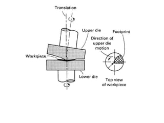
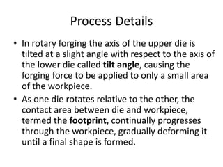
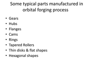
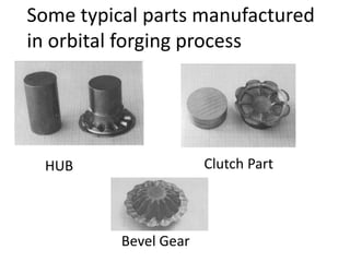
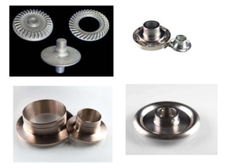
NATIONAL INSTITUTE OF FOUNDRY & FORGE TECHNOLOGY ,
RANCHI
ORBITAL FORGING
- Presented By
SHASHANK KULSHRESTHA
M.TECH (2016-18), FF16M12
FOUNDRY & FORGE TECHNOLOGY
ORBITAL FORGING
• Orbital forging is a two-die
forging process that deforms only
a small portion of the workpiece
at a time in a continuous manner.
• Also known as Rotary Forging.
Process Details
• In rotary forging the axis of the upper die is
tilted at a slight angle with respect to the axis of
the lower die called tilt angle, causing the
forging force to be applied to only a small area
of the workpiece.
• As one die rotates relative to the other, the
contact area between die and workpiece,
termed the footprint, continually progresses
through the workpiece, gradually deforming it
until a final shape is formed.
Significance of Tilt Angle
• The tilt angle between the two dies plays a
major role in determining the amount of
forging force that is applied to the workpiece.
continued….
Larger tilt angle
Smaller footprint
Smaller force
required to complete the same deformation as
compared to a larger contact area.
&
vice-versa
Continued…….
Can we take too large tilt angle, to decrease the
forging force ?
• The larger the tilt angle the more difficult are the
machine design and maintenance problems,
because the drive and bearing system for the
tilted die is subjected to large lateral loads and is
more difficult to maintain.
• In addition, a larger tilt angle causes greater
frame deflection within the forge, making it
difficult to maintain a consistently high level of
precision.
• So,tilt angles are commonly about 1 to 2°.
Classification
Based on
motion of
dies
rotating-die
forging
rocking-die
forging
Rotating Die Forging
• In rotating-die forges, both dies rotate about
their own axis, but neither die rocks or
precesses about the axis of the other die.
Rocking Die Forging
• In rocking-die, or orbital, forges, the upper die
rocks across the face of the lower die in a variety
of fashions.
• The most common form is where the upper die
orbits in a circular pattern about the axis of the
lower die.
• In this case, the upper die can also either rotate
or remain stationary in relation to its own axis.
• Other examples of rocking-die motion include the
rocking of the upper die across the workpiece in a
straight, spiral, or planetary pattern.
Schematic of rocking-die forge
Different Patterns of Upper Die Motion
Continued……….
•Orbital (circular) motion - most commonly used,
especially when forging have relatively thin
parts,where high deformation is needed throughout
the whole part volume.
• Planetary Motion- For parts with large ribs and
flanges.
•Spiral motion -suitable for parts in which most
material flow occurs in central region.
•Straight line motion -convenient for long, narrow
parts.
Applications
• Rotary forging is generally considered to be a
substitute for conventional drop-hammer or
press forging.
• In addition,rotary forging can be used to
produce parts that would otherwise have to
be completely machined because of their
shape or dimensions.
• Currently, approximately one-quarter to one-
third of all parts that are either hammer or
press forged could be formed on a rotary
forge.
• These parts include symmetric and asymmetric
shapes.
• In the current technology, rotating or orbiting
die forges are mainly limited to the production
of symmetrical parts.
• Through a more complex die operation, rocking-
die forges are able to produce both symmetric
and asymmetric pieces.
Some typical parts manufactured in
orbital forging process
• Gears
• Hubs
• Flanges
• Cams
• Rings
• Tapered Rollers
• Thin disks & flat shapes
• Hexagonal shapes
Some typical parts manufactured
in orbital forging process
HUB Clutch Part
Bevel Gear
Workpiece Materials
• Any material, ferrous or nonferrous, that has
adequate ductility and cold-forming qualities
can be rotary forged.
• These materials include -
 carbon and alloy steels,
 stainless steels,
 brass,
 aluminum alloys.
Advantages
• Low Axial Force - The primary advantage of rotary forging is in the low
axial force required to form a part. Because only a small area of the die is in
contact with the workpiece at any given time, rotary forging requires as little
as one-tenth the force required by conventional forging techniques.
• Lower machine and die deformation & Less die-
workpiece friction- due to smaller forging forces.
• High degree of accuracy - low equipment wear makes rotary
forging a precision production process that can be used to form intricate parts
to a high degree of accuracy.
• Relatively short operation time - Parts that require subsequent
finishing after conventional forging can be rotary forged to net shape in
one step.The average cycle time for a moderately complex part is 10 to
15s
A cycle time in the range of 10 to 15 s will yield approximately 300
pieces per hour.
• Lower tooling cost -Tooling costs for rotary forging are often
lower than those for conventional forging. Because of the lower forging
loads, die manufacture is easier, and the required die strength is much
lower. Die change and adjustment times are also much lower; dies can
be changed in as little as 15 min. These moderate costs make the
process economically attractive for either short or long production runs,
thus permitting greater flexibility in terms of machine use and batch
sizes.
• Less environmental hazards & complications -
Because impact is not used in rotary forging, there are fewer
environmental hazards than in conventional forging techniques.
Complications such as noise, vibrations, fumes, and dirt are virtually
non-existent.
• Can be cold forged -The smaller forging forces allow many
parts to be cold forged that would conventionally require hot forging,
resulting in decreased die wear and greater ease in handling parts after
forging. This is in addition to the favorable grain structure that results
from the cold working of metals.
Disadvantages
• Relative newness of the current technology- there is a need
for a convenient method of determining whether or not a piece can be
produced by rotary forging. Like other forging processes, the current process is
basically one of trial and error.
• High initial capital investment- A set of dies must be constructed
and tested for each part not previously produced by rotary forging in order to
determine whether or not the part is suitable for rotary forging.
• Constraints due to materials, specific shape & geometry
of parts- rotary forging may not be suitable for a variety of reasons like
the material may experience cracking during the forging process; the
finished part may undergo elastic spring-back; or there may be areas on
the workpiece that do not conform to the die contour, leaving a gap
between die and workpiece, such as central thinning.
• Design of rotary forge machines- a major problem lies in
the design of rotary forge machines. The large lateral forces associated
with the unique die motion make the overall frame design of the
machines more difficult. These large forces must be properly supported
by the frame in order for the forge to maintain a consistent level of
accuracy. Conventional forges present a less troublesome design problem
because they do not experience such a wide range of die motion.
CONCLUSION
• The rotary forges that are currently in use are
adequate for forming the parts that they
presently produce, but the accuracy of these
parts is not as great as it can be.
• Further research and additional production
experience are necessary before these forges
reach their full practical potential.
ORBITAL FORGING

ORBITAL FORGING

  • 1.
    NATIONAL INSTITUTE OFFOUNDRY & FORGE TECHNOLOGY , RANCHI ORBITAL FORGING - Presented By SHASHANK KULSHRESTHA M.TECH (2016-18), FF16M12 FOUNDRY & FORGE TECHNOLOGY
  • 2.
    ORBITAL FORGING • Orbitalforging is a two-die forging process that deforms only a small portion of the workpiece at a time in a continuous manner. • Also known as Rotary Forging.
  • 4.
    Process Details • Inrotary forging the axis of the upper die is tilted at a slight angle with respect to the axis of the lower die called tilt angle, causing the forging force to be applied to only a small area of the workpiece. • As one die rotates relative to the other, the contact area between die and workpiece, termed the footprint, continually progresses through the workpiece, gradually deforming it until a final shape is formed.
  • 5.
    Significance of TiltAngle • The tilt angle between the two dies plays a major role in determining the amount of forging force that is applied to the workpiece. continued….
  • 6.
    Larger tilt angle Smallerfootprint Smaller force required to complete the same deformation as compared to a larger contact area. & vice-versa Continued…….
  • 7.
    Can we taketoo large tilt angle, to decrease the forging force ? • The larger the tilt angle the more difficult are the machine design and maintenance problems, because the drive and bearing system for the tilted die is subjected to large lateral loads and is more difficult to maintain. • In addition, a larger tilt angle causes greater frame deflection within the forge, making it difficult to maintain a consistently high level of precision. • So,tilt angles are commonly about 1 to 2°.
  • 8.
  • 9.
    Rotating Die Forging •In rotating-die forges, both dies rotate about their own axis, but neither die rocks or precesses about the axis of the other die.
  • 10.
    Rocking Die Forging •In rocking-die, or orbital, forges, the upper die rocks across the face of the lower die in a variety of fashions. • The most common form is where the upper die orbits in a circular pattern about the axis of the lower die. • In this case, the upper die can also either rotate or remain stationary in relation to its own axis. • Other examples of rocking-die motion include the rocking of the upper die across the workpiece in a straight, spiral, or planetary pattern.
  • 11.
  • 12.
    Different Patterns ofUpper Die Motion Continued……….
  • 14.
    •Orbital (circular) motion- most commonly used, especially when forging have relatively thin parts,where high deformation is needed throughout the whole part volume. • Planetary Motion- For parts with large ribs and flanges. •Spiral motion -suitable for parts in which most material flow occurs in central region. •Straight line motion -convenient for long, narrow parts.
  • 15.
    Applications • Rotary forgingis generally considered to be a substitute for conventional drop-hammer or press forging. • In addition,rotary forging can be used to produce parts that would otherwise have to be completely machined because of their shape or dimensions. • Currently, approximately one-quarter to one- third of all parts that are either hammer or press forged could be formed on a rotary forge.
  • 16.
    • These partsinclude symmetric and asymmetric shapes. • In the current technology, rotating or orbiting die forges are mainly limited to the production of symmetrical parts. • Through a more complex die operation, rocking- die forges are able to produce both symmetric and asymmetric pieces.
  • 17.
    Some typical partsmanufactured in orbital forging process • Gears • Hubs • Flanges • Cams • Rings • Tapered Rollers • Thin disks & flat shapes • Hexagonal shapes
  • 18.
    Some typical partsmanufactured in orbital forging process HUB Clutch Part Bevel Gear
  • 20.
    Workpiece Materials • Anymaterial, ferrous or nonferrous, that has adequate ductility and cold-forming qualities can be rotary forged. • These materials include -  carbon and alloy steels,  stainless steels,  brass,  aluminum alloys.
  • 21.
    Advantages • Low AxialForce - The primary advantage of rotary forging is in the low axial force required to form a part. Because only a small area of the die is in contact with the workpiece at any given time, rotary forging requires as little as one-tenth the force required by conventional forging techniques. • Lower machine and die deformation & Less die- workpiece friction- due to smaller forging forces. • High degree of accuracy - low equipment wear makes rotary forging a precision production process that can be used to form intricate parts to a high degree of accuracy. • Relatively short operation time - Parts that require subsequent finishing after conventional forging can be rotary forged to net shape in one step.The average cycle time for a moderately complex part is 10 to 15s A cycle time in the range of 10 to 15 s will yield approximately 300 pieces per hour.
  • 22.
    • Lower toolingcost -Tooling costs for rotary forging are often lower than those for conventional forging. Because of the lower forging loads, die manufacture is easier, and the required die strength is much lower. Die change and adjustment times are also much lower; dies can be changed in as little as 15 min. These moderate costs make the process economically attractive for either short or long production runs, thus permitting greater flexibility in terms of machine use and batch sizes. • Less environmental hazards & complications - Because impact is not used in rotary forging, there are fewer environmental hazards than in conventional forging techniques. Complications such as noise, vibrations, fumes, and dirt are virtually non-existent. • Can be cold forged -The smaller forging forces allow many parts to be cold forged that would conventionally require hot forging, resulting in decreased die wear and greater ease in handling parts after forging. This is in addition to the favorable grain structure that results from the cold working of metals.
  • 23.
    Disadvantages • Relative newnessof the current technology- there is a need for a convenient method of determining whether or not a piece can be produced by rotary forging. Like other forging processes, the current process is basically one of trial and error. • High initial capital investment- A set of dies must be constructed and tested for each part not previously produced by rotary forging in order to determine whether or not the part is suitable for rotary forging. • Constraints due to materials, specific shape & geometry of parts- rotary forging may not be suitable for a variety of reasons like the material may experience cracking during the forging process; the finished part may undergo elastic spring-back; or there may be areas on the workpiece that do not conform to the die contour, leaving a gap between die and workpiece, such as central thinning.
  • 24.
    • Design ofrotary forge machines- a major problem lies in the design of rotary forge machines. The large lateral forces associated with the unique die motion make the overall frame design of the machines more difficult. These large forces must be properly supported by the frame in order for the forge to maintain a consistent level of accuracy. Conventional forges present a less troublesome design problem because they do not experience such a wide range of die motion.
  • 25.
    CONCLUSION • The rotaryforges that are currently in use are adequate for forming the parts that they presently produce, but the accuracy of these parts is not as great as it can be. • Further research and additional production experience are necessary before these forges reach their full practical potential.