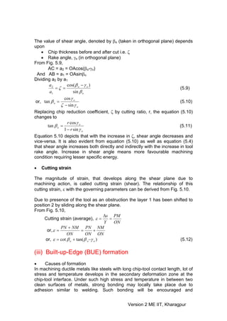
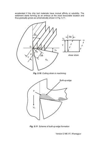
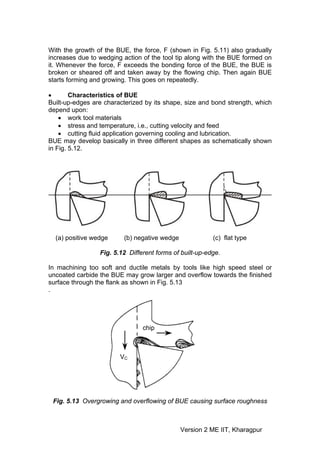
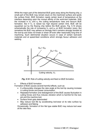
(1) Chip formation in machining occurs through shear deformation in ductile materials and brittle fracture in brittle materials. In ductile materials, compression ahead of the tool leads to shear along the plane of maximum shear stress. (2) Geometric properties of chips include chip thickness ratio, shear angle, and cutting strain. A higher chip thickness ratio requires more cutting force. Shear angle increases with tool rake angle and chip thickness ratio. (3) Built-up edge formation occurs at the tool-chip interface in ductile materials due to welding between tool and chip surfaces under high stress and temperature conditions.


![Knowledge of basic mechanism(s) of chip formation helps to understand the
characteristics of chips and to attain favourable chip forms.
• Mechanism of chip formation in machining ductile materials
During continuous machining the uncut layer of the work material just ahead
of the cutting tool (edge) is subjected to almost all sided compression as
indicated in Fig. 5.1.
a1: chip thickness (before cut)
a2: chip thickness (after cut)
Work Vf
F
Tool N
R
πo
VC
Fig. 5.1 Compression of work material (layer) ahead of the tool tip
The force exerted by the tool on the chip arises out of the normal force, N and
frictional force, F as indicated in Fig. 5.1.
Due to such compression, shear stress develops, within that compressed
region, in different magnitude, in different directions and rapidly increases in
magnitude. Whenever and wherever the value of the shear stress reaches or
exceeds the shear strength of that work material in the deformation region,
yielding or slip takes place resulting shear deformation in that region and the
plane of maximum shear stress. But the forces causing the shear stresses in
the region of the chip quickly diminishes and finally disappears while that
region moves along the tool rake surface towards and then goes beyond the
point of chip-tool engagement. As a result the slip or shear stops propagating
long before total separation takes place. In the mean time the succeeding
portion of the chip starts undergoing compression followed by yielding and
shear. This phenomenon repeats rapidly resulting in formation and removal of
chips in thin layer by layer. This phenomenon has been explained in a simple
way by Piispannen [1] using a card analogy as shown in Fig. 5.2.
In actual machining chips also, such serrations are visible at their upper
surface as indicated in Fig. 5.2. The lower surface becomes smooth due to
further plastic deformation due to intensive rubbing with the tool at high
pressure and temperature. The pattern of shear deformation by lamellar
sliding, indicated in the model, can also be seen in actual chips by proper
mounting, etching and polishing the side surface of the machining chip and
observing under microscope.
Version 2 ME IIT, Kharagpur](https://image.slidesharecdn.com/lm-05-110803105033-phpapp02/85/Lm-05-4-320.jpg)
![The pattern and extent of total deformation of the chips due to the primary and
the secondary shear deformations of the chips ahead and along the tool face,
as indicated in Fig. 5.3, depend upon
[1] Piispannen V., “Theory of formation of metal chips”, J. Applied Physics, Vol. 19, No. 10, 1948, pp. 876.
• work material
• tool; material and geometry
• the machining speed (VC) and feed (so)
• cutting fluid application
chip
VC Tool
(a) Shifting of the postcards by partial (b) Chip formation by shear in
sliding against each other lamella.
Fig. 5.2 Piispanen model of card analogy to explain chip formation in
machining ductile materials
primary deformation (shear)
zone
WORK
CHIP
secondary deformation zone
VC
Fig. 5.3 Primary and secondary deformation zones in the chip.
The overall deformation process causing chip formation is quite complex and
hence needs thorough experimental studies for clear understanding the
phenomena and its dependence on the affecting parameters. The feasible
and popular experimental methods [2] for this purpose are:
• Study of deformation of rectangular or circular grids marked on the side
surface as shown in Fig. 5.4
Version 2 ME IIT, Kharagpur](https://image.slidesharecdn.com/lm-05-110803105033-phpapp02/85/Lm-05-5-320.jpg)
![[2] Bhattacharya, A.., “Metal cutting – Theory and Practice”, Book, New Central Book Agency, Kolkata.
• Microscopic study of chips frozen by drop tool or quick stop apparatus
• Study of running chips by high speed camera fitted with low
magnification microscope.
(a) rectangular grids (b) circular grids
Fig. 5.4 Pattern of grid deformation during chip formation.
It has been established by several analytical and experimental methods
including circular grid deformation that though the chips are initially
compressed ahead of the tool tip, the final deformation is accomplished
mostly by shear in machining ductile materials.
However, machining of ductile materials generally produces flat, curved or
coiled continuous chips.
• Mechanism of chip formation in machining brittle materials
The basic two mechanisms involved in chip formation are
• Yielding – generally for ductile materials
• Brittle fracture – generally for brittle materials
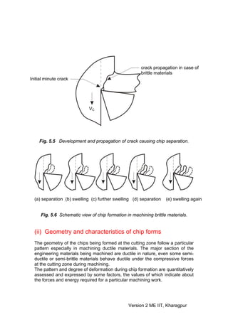
During machining, first a small crack develops at the tool tip as shown in Fig.
5.5 due to wedging action of the cutting edge. At the sharp crack-tip stress
concentration takes place. In case of ductile materials immediately yielding
takes place at the crack-tip and reduces the effect of stress concentration and
prevents its propagation as crack. But in case of brittle materials the initiated
crack quickly propagates, under stressing action, and total separation takes
place from the parent workpiece through the minimum resistance path as
indicated in Fig. 5.5.
Machining of brittle material produces discontinuous chips and mostly of
irregular size and shape. The process of forming such chips is schematically
shown in Fig. 5.6.
Version 2 ME IIT, Kharagpur](https://image.slidesharecdn.com/lm-05-110803105033-phpapp02/85/Lm-05-6-320.jpg)
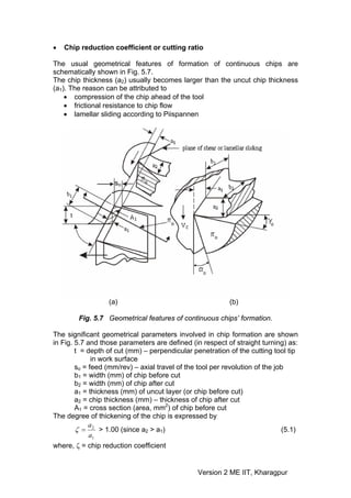
![a1= sosinφ (5.2)
where φ = principal cutting edge angle
Larger value of ζ means more thickening i.e., more effort in terms of forces or
energy required to accomplish the machining work. Therefore it is always
desirable to reduce a2 or ζ without sacrificing productivity, i.e. metal removal
rate (MRR).
Chip thickening is also often expressed by the reciprocal of ζ as,
1 a
=r= 1 (5.3)
ζ a2
where, r = cutting ratio
The value of chip reduction coefficient, ζ (and hence cutting ratio) depends
mainly upon
• tool rake angle, γ
• chip-tool interaction, mainly friction,μ
Roughly in the following way [3]
π
μ ( −γ o )
ζ =e 2
[for orthogonal cutting] (5.4)
π/2 and γo are in radians
The simple but very significant expression (5.4) clearly depicts that the value
of ζ can be desirably reduced by
• Using tool having larger positive rake
• Reducing friction by using lubricant
The role of rake angle and friction at the chip-tool interface on chip reduction
coefficient are also schematically shown in Fig. 5.8.
Chip reduction coefficient, ζ
μ (friction coefficient)
Rake angle, γ
Fig. 5.8 Role of rake angle and friction on chip reduction coefficient
Chip reduction coefficient, ζ is generally assessed and expressed by the ratio
of the chip thickness, after (a2) and before cut (a1) as in equation 5.1.
But ζ can also be expressed or assessed by the ratio of
Version 2 ME IIT, Kharagpur](https://image.slidesharecdn.com/lm-05-110803105033-phpapp02/85/Lm-05-9-320.jpg)
![[3] Kronenberg, M., “A new approach to some relationships in the Theory of Metal Cutting”, J. Applied
Physics, Vol.6, No. 6, 1945.
• Total length of the chip before (L1) and after cut (L2)
• Cutting velocity, VC and chip velocity, Vf
Considering total volume of chip produced in a given time,
a1b1L1 = a2b2L2 (5.5)
The width of chip, b generally does not change significantly during machining
unless there is side flow for some adverse situation.
Therefore assuming, b1=b2 in equation (5.5), ζ comes up to be,
⎛ a ⎞ L
ζ ⎜= 2 ⎟ = 1
⎜ a ⎟ L (5.6)
⎝ 1 ⎠ 2
Again considering unchanged material flow (volume) ratio, Q
Q = (a1b1)VC = (a2b2)Vf (5.7)
Taking b1=b2,
⎛ a ⎞ V
ζ ⎜= 2 ⎟ = C
⎜ a ⎟ V (5.8)
⎝ 1 ⎠ f
Equation (5.8) reveals that the chip velocity, Vf will be lesser than the cutting
⎛ 1⎞
velocity, VC and the ratio is equal to the cutting ratio, r ⎜ = ⎟
⎜ ζ⎟
⎝ ⎠
• Shear angle
It has been observed that during machining, particularly ductile materials, the
chip sharply changes its direction of flow (relative to the tool) from the
direction of the cutting velocity, VC to that along the tool rake surface after
thickening by shear deformation or slip or lamellar sliding along a plane. This
plane is called shear plane and is schematically shown in Fig. 5.9.
Shear plane: Shear plane is the plane of separation of work material layer in
the form of chip from the parent body due to shear along that plane.
Shear angle: Angle of inclination of the shear plane from the direction of
cutting velocity [as shown in Fig. 5.9].
VC'
Shear plane
a1
A
B
βo a2
(βo - γo)
O C γo
VC
πo
Fig. 5.9 Shear plane and shear angle in chip formation
Version 2 ME IIT, Kharagpur](https://image.slidesharecdn.com/lm-05-110803105033-phpapp02/85/Lm-05-10-320.jpg)
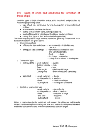
![Answers
A. Quiz Test
1 – (a)
2 – (d)
3 – (c)
4 – (b)
B. Numerical Problem
a2 a2 0 .5
ζ = = = = 2 .5
a1 so sin φ 0.2 x sin 90o
cos γ o cos 0o
tan β o = = [∵ γ o = 0o ]
ζ − sin γ o 2.5 − sin 0o
1 1
= = = 0 .4
ζ 2 .5
∴ β o = tan−1(0.4) = 21.8o
Version 2 ME IIT, Kharagpur](https://image.slidesharecdn.com/lm-05-110803105033-phpapp02/85/Lm-05-17-320.jpg)