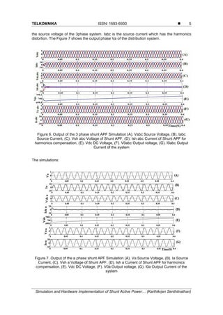
This paper presents the design, simulation, and hardware implementation of a Shunt Active Power Filter (SAPF) utilizing Synchronous Reference Frame (SRF) theory to effectively eliminate current harmonics in electrical systems. The SAPF, based on a Voltage Source Inverter (VSI) topology, was successfully simulated in MATLAB/Simulink and implemented in hardware using an ATmega microcontroller, demonstrating significant reduction in Total Harmonic Distortion (THD) levels. Results showed THD of 0.95% in simulation and 4.60% in real-time implementation, indicating the effectiveness of the proposed method in maintaining harmonic levels within acceptable limits.
![TELKOMNIKA, Vol.16, No.1, February 2018, pp. 1-9
ISSN: 1693-6930, accredited A by DIKTI, Decree No: 58/DIKTI/Kep/2013
DOI: 10.12928/TELKOMNIKA.v16i1.6524 1
Received October 9, 2017; Revised January 19, 2018; Accepted January 29, 2018
Simulation and Hardware Implementation of Shunt
Active Power Filter Based on Synchronous Reference
Frame Theory
Karthikrjan Senthilnathan
1
, Iyswarya Annapoorani*
2
, S.Ravi
3
1,2
School of Electrical Engineering, VIT University, Chennai, India
3
Department of Electrical Engineering, Botswana International University of Science and Technology,
Botswana
*Corresponding author, e-mail: Iyswarya.annapoorani@vit.ac.in
Abstract
This paper describes about the Shunt Active Power Filter (SAPF) for the elimination of the current
harmonics in the line side. The Active Power Filter is based on the Voltage Source Inverter (VSI) topology.
The Synchronous Reference Frame (SRF) theory based control strategy is utilized for SAPF. The SAPF
has the better performance for compensation of harmonics. The simulation of shunt active power filter is
performed in MATLAB/Simulink. The SAPF is implemented in hardware protptype with ATMEGA 8
Microcontroller. The Simulation and Hardware result shows that the current harmonics are eliminated in
the system.
Keywords: shunt active power filter, voltage source converters, harmonics, synchronous reference frame
Copyright © 2018 Universitas Ahmad Dahlan. All rights reserved.
1. Introduction
Harmonics are the major disturbance in distribution system, the efficiency of the system
reduces and cause damage to the equipment’s. The elimination of harmonics is done by various
methods used are using passive LC filter and Active Power Filters (APF) [1]-[4]. The APF can
be connected as shunt and series configuration. The shunt connection gives better harmonics
compensation than the series connection [5-8]. The quality of power delivering to the system to
be maintained within their limits and compensation techniques also to be implemented to make
the system as efficient one. The APF has the property of compensating the current and voltage
related problems. The shunt active power filter is the most promising approach to compensate
the current harmonics [9]-[10] in the system. The converter connected to the system which acts
as the APF for the injecting the negative harmonics [11] to the system for the compensating the
harmonics. The Shunt APF [12]-[13] has the converter which is based on the Voltage Source
Inverter (VSI) topology using Insulated Gate Bipolar Transistor (IGBT) device. The gate pulse
for the IGBT is generated by the Synchronous Reference Frame (SRF) [14] theory for the
reference signal calculation and compared using the hysteresis controller [19-22].
The SAP Filter based on the VSI topology is connected through the capacitor which
delivers the supply for the compensation of the current harmonics in distribution system. The
Total Harmonics Distortion (THD) [15-18] has the acceptable limit for both voltage and current.
The THD of instantaneous current I1, I2, I3 up to In is given by square root of the mean
(average) value of the squared function of the instantaneous values.The THD limit is 5% for
Voltage and 8% for Current as per IEEE 519 standards. The Current Harmonics is calculated by
the Equation (1) and (2).
𝑇𝐻𝐷% 𝑓𝑢𝑛𝑑𝑎𝑚𝑒𝑛𝑡𝑎𝑙 = (
𝐼𝑟𝑚𝑠 (𝑑𝑖𝑠𝑡𝑜𝑟𝑡𝑖𝑜𝑛)
𝐼𝑓𝑢𝑛𝑑𝑎𝑚𝑒𝑛𝑡𝑎𝑙
) (1)
Where, Irms (distortion) is denoted by
𝐼
𝑟𝑚𝑠(𝑑𝑖𝑠𝑡𝑜𝑟𝑡𝑖𝑜𝑛)= √𝐼1
2+𝐼2
2+𝐼3
2+⋯ (2)](https://image.slidesharecdn.com/16524-200820054534/85/Simulation-and-Hardware-Implementation-of-Shunt-Active-Power-Filter-Based-on-Synchronous-Reference-Frame-Theory-1-320.jpg)
![TELKOMNIKA, Vol.16, No.1, February 2018, pp. 1-9
ISSN: 1693-6930, accredited A by DIKTI, Decree No: 58/DIKTI/Kep/2013
DOI: 10.12928/TELKOMNIKA.v16i1.6524 1
Received October 9, 2017; Revised January 19, 2018; Accepted January 29, 2018
Simulation and Hardware Implementation of Shunt
Active Power Filter Based on Synchronous Reference
Frame Theory
Karthikrjan Senthilnathan
1
, Iyswarya Annapoorani*
2
, S.Ravi
3
1,2
School of Electrical Engineering, VIT University, Chennai, India
3
Department of Electrical Engineering, Botswana International University of Science and Technology,
Botswana
*Corresponding author, e-mail: Iyswarya.annapoorani@vit.ac.in
Abstract
This paper describes about the Shunt Active Power Filter (SAPF) for the elimination of the current
harmonics in the line side. The Active Power Filter is based on the Voltage Source Inverter (VSI) topology.
The Synchronous Reference Frame (SRF) theory based control strategy is utilized for SAPF. The SAPF
has the better performance for compensation of harmonics. The simulation of shunt active power filter is
performed in MATLAB/Simulink. The SAPF is implemented in hardware protptype with ATMEGA 8
Microcontroller. The Simulation and Hardware result shows that the current harmonics are eliminated in
the system.
Keywords: shunt active power filter, voltage source converters, harmonics, synchronous reference frame
Copyright © 2018 Universitas Ahmad Dahlan. All rights reserved.
1. Introduction
Harmonics are the major disturbance in distribution system, the efficiency of the system
reduces and cause damage to the equipment’s. The elimination of harmonics is done by various
methods used are using passive LC filter and Active Power Filters (APF) [1]-[4]. The APF can
be connected as shunt and series configuration. The shunt connection gives better harmonics
compensation than the series connection [5-8]. The quality of power delivering to the system to
be maintained within their limits and compensation techniques also to be implemented to make
the system as efficient one. The APF has the property of compensating the current and voltage
related problems. The shunt active power filter is the most promising approach to compensate
the current harmonics [9]-[10] in the system. The converter connected to the system which acts
as the APF for the injecting the negative harmonics [11] to the system for the compensating the
harmonics. The Shunt APF [12]-[13] has the converter which is based on the Voltage Source
Inverter (VSI) topology using Insulated Gate Bipolar Transistor (IGBT) device. The gate pulse
for the IGBT is generated by the Synchronous Reference Frame (SRF) [14] theory for the
reference signal calculation and compared using the hysteresis controller [19-22].
The SAP Filter based on the VSI topology is connected through the capacitor which
delivers the supply for the compensation of the current harmonics in distribution system. The
Total Harmonics Distortion (THD) [15-18] has the acceptable limit for both voltage and current.
The THD of instantaneous current I1, I2, I3 up to In is given by square root of the mean
(average) value of the squared function of the instantaneous values.The THD limit is 5% for
Voltage and 8% for Current as per IEEE 519 standards. The Current Harmonics is calculated by
the Equation (1) and (2).
𝑇𝐻𝐷% 𝑓𝑢𝑛𝑑𝑎𝑚𝑒𝑛𝑡𝑎𝑙 = (
𝐼𝑟𝑚𝑠 (𝑑𝑖𝑠𝑡𝑜𝑟𝑡𝑖𝑜𝑛)
𝐼𝑓𝑢𝑛𝑑𝑎𝑚𝑒𝑛𝑡𝑎𝑙
) (1)
Where, Irms (distortion) is denoted by
𝐼
𝑟𝑚𝑠(𝑑𝑖𝑠𝑡𝑜𝑟𝑡𝑖𝑜𝑛)= √𝐼1
2+𝐼2
2+𝐼3
2+⋯ (2)](https://image.slidesharecdn.com/16524-200820054534/75/Simulation-and-Hardware-Implementation-of-Shunt-Active-Power-Filter-Based-on-Synchronous-Reference-Frame-Theory-1-2048.jpg)
![ ISSN: 1693-6930
TELKOMNIKA Vol. 16, No. 1, February 2018 : 1 – 9
2
2. Shunt Active Power Filter (SAPF)
Expl The Shunt Active Power Filter (SAPF) has the robust control of current harmonics
within the limit and makes the system to be more efficient. The Figure 1 shows the configuration
of the Shunt APF [3]. The coupling transformer connected to the system for the injection of the
compensating harmonics to eliminate the distortion. The switching converter is based on VSC
topology of three leg configuration of IGBT components. The Capacitor C connected along the
DC terminal of the converter which supplies the DC voltage VDC to the converter. The 6 pulse
converters which are operated in the 1800 phase shift to the IGBT of same leg, 1200 between
the two legs and 600 phase shift between the n+ 1 component.
Figure 1. Shunt Active Power Filter (SAPF) Configuration
3. Control Strategy for SAPF based on Synchronous Reference Frame (SRF) Theory
The control strategy of the system is to control the converter for the injections of the
negative harmonics for the compensation of the system. The converter output is controlled by
the gate pulse given to the IGBT’s. This is achieved by the Synchronous Reference Frame
Theory [4]. The SRF [6] theory is based on the synchronous machine in which for the analysis
of 3phase system is made easy. The 3phase system abc is converted to the direct and
quadrature axis quantities dq0. For the shunt APF is load current is considered for the reference
signal calculation and pulse is generated. The Equation (3), (4), (5) represents the current for
the three phases which is converted to dq0 for the balanced state.
𝑖 𝑎 = 𝐼 𝑚 𝑠𝑖𝑛𝜔𝑠 𝑡 (3)
𝑖 𝑏 = 𝐼 𝑚sin (𝜔𝑠 𝑡 −
2𝜋
3
) (4)
𝑖 𝑎 = 𝐼 𝑚sin (𝜔𝑠 𝑡 +
2𝜋
3
) (5)
The transformation matrix for the ia, ib ic is given by Equation (6),
[
𝑖 𝑎
𝑖 𝑏
𝑖 𝑐
] = [
𝑐𝑜𝑠𝜃 −𝑠𝑖𝑛𝜃 1
𝑐𝑜𝑠 (𝜃 −
2𝜋
3
) −𝑠𝑖𝑛𝜃 (𝜃 −
2𝜋
3
) 1
𝑐𝑜𝑠 (𝜃 +
2𝜋
3
) −𝑠𝑖𝑛𝜃 (𝜃 +
2𝜋
3
) 1
] [
𝑖 𝑑
𝑖 𝑞
𝑖0
] (6)
The transformation of matrix from abc to dq0 and inverse transform of matrix dq0 to abc
is simultaneously performed to calculate the reference signal for the pulse generation. The](https://image.slidesharecdn.com/16524-200820054534/85/Simulation-and-Hardware-Implementation-of-Shunt-Active-Power-Filter-Based-on-Synchronous-Reference-Frame-Theory-2-320.jpg)
![TELKOMNIKA ISSN: 1693-6930
Simulation and Hardware Implementation of Shunt Active Power… (Karthikrjan Senthilnathan)
3
Equations (7), (8) and (9) show the transformation of dq0 under the balanced state. The id, iq, i0
are the currents of direct, quadrature and zero axis of the system which is obtained from the
inverse transformation.
id = kd
3
2
Imsin(ωst − θ) (7)
iq = −kq
3
2
Imsin(ωst − θ) (8)
i0 =
1
3
(𝑖 𝑎 + 𝑖 𝑏 + 𝑖 𝑐) (9)
The transformation matrix for the dq0 transform is given by (10),
[
𝑖 𝑑
𝑖 𝑞
𝑖0
] =
2
3
[
𝑐𝑜𝑠𝜃 𝑐𝑜𝑠 (𝜃 −
2𝜋
3
) 𝑐𝑜𝑠 (𝜃 +
2𝜋
3
)
−𝑠𝑖𝑛𝜃 −𝑠𝑖𝑛𝜃 (𝜃 −
2𝜋
3
) −𝑠𝑖𝑛𝜃 (𝜃 +
2𝜋
3
)
1
2
1
2
1
2 ]
(10)
The DC voltage across the capacitor Vdc is to be kept within a range of a voltage of
705V throughout the operation of the system. The PI controller is connected to output of the
voltage measurement Vdc and a constant of 705 is compared with the measured voltage of the
system. The block diagram for the SRF theory implementation is represented in Figure 2.
Figure 2. Block diagram representation of Synchronous Reference Frame (SRF) theory
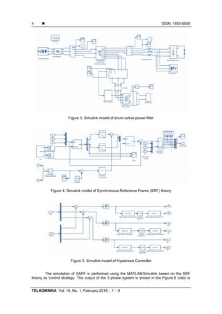
4. Simulation of Shunt Active Power Filter
The shunt active power filter (SAPF) design for three phase systems is modelled in
MATLAB. The load considered here is reftified RL and three phase RLC static load. The shunt
active filter has the ability to compensate the current harmonics caused by the non linear loads
in power systems. The control strategy based on SRF theory for SAPF is simulated in
MATLAB/Simulink shown in the Figure 3.
The Figure 4 shows the Simulink model of the SRF theory which is used for reference
signal calculation. The reference signal is compared with the measured signal by using the
hysteresis band for the PWM pulse for the IGBT operation. The Figure 5 shows the simulation
of the Hysteresis band for the PWM pulse generation.](https://image.slidesharecdn.com/16524-200820054534/85/Simulation-and-Hardware-Implementation-of-Shunt-Active-Power-Filter-Based-on-Synchronous-Reference-Frame-Theory-3-320.jpg)
![ ISSN: 1693-6930
TELKOMNIKA Vol. 16, No. 1, February 2018 : 1 – 9
8
Figure 14. Output Voltage of Real Time implementation
The current harmonics is calculated and displayed in the LCD display. The THD
calculated using the Controller for the hardware is 4.60 % and it is shown in the Figure 16.
Figure 16. THD calculated value for real time implementation
6. Conclusion
This paper proposes the simulation and real time implementation of the shunt active
power filter (SAPF) based on the synchronous reference frame (SRF) theory and the real time
implementation using ATMEGA controller. The results shows that the harmonic level in the
system is maintained within the acceptable limit are about 0.95 % for the simulation and 4.60%
for the real time implementation of the shunt active power filter. The further improvement can be
done using various control algorithms for the elimination of harmonics of the system.
References
[1] L Gyugui, E Strycula. Active AC power filters. Conf.Rec. IEEE LAS Annu. Meeting. IL. 1976: 529-
535.
[2] E Ozdemir, M Ucar, M Kesler, M Kale. A simplified control algorithm for shunt active power filter
without load and filter current measurement. In Proc. 32nd IEEE IECON. Paris, France. 2006: 2599-
2604.
[3] E Ozdemir, M Ucar, M Kesler, M Kale. The design and implementation of a shunt active power filter
based on source current measurement. In Proc. IEEE EMDC. Antalya, Turkey. 2007: 608-613.
[4] P Rodríguez, J Pou, J Bergas, JI Candela, RP Burgos, D Boroyevich. Decoupled double
synchronous reference frame PLL for power converters control. IEEE Trans. Power Electron. 2007;
22(2): 584-592.
[5] RM Santos Filho, PF Seixas, PC Cortizo, LAB Torres, AF Souza. Comparison of three single-phase
PLL algorithms for UPS applications. IEEE Trans. Ind. Electron. 2008; 55(8): 2923-2932.
[6] P Rodriguez, J Pou, J Bergas, JI Candela, RP Burgos, D Boroyevich. Decoupled double
synchronous reference frame PLL for power converters control. IEEE Trans. Power Electron. 2007;
22(2): 584-592.
[7] A Luo, Z Shuai, W Zhu, ZJ Shen. Combined system for harmonic suppression and reactive power
compensation. IEEE Trans. Ind.Electron. 2009; 56(2): 418-428.
[8] SAO da Silva, RA Modesto. A comparative analysis of SRF based controllers applied to active power
line conditioners. In Proc. 34
th
IEEE IECON. 2008: 405-410.
[9] Rajasekaran Dharmalingam, Subhransu Sekhar Dash, Karthikrajan Senthilnathan, Arun Bhaskar
Mayilvaganan, Subramani Chinnamuthu. Power Quality Improvement by Unified Power Quality](https://image.slidesharecdn.com/16524-200820054534/85/Simulation-and-Hardware-Implementation-of-Shunt-Active-Power-Filter-Based-on-Synchronous-Reference-Frame-Theory-8-320.jpg)
![TELKOMNIKA ISSN: 1693-6930
Simulation and Hardware Implementation of Shunt Active Power… (Karthikrjan Senthilnathan)
9
Conditioner Based on CSC Topology Using Synchronous Reference Frame Theory. The Scientific
World Journal. 2014; 2014.
[10] G Rajpriya, Samikannu Ravi, Ahmad Mujahid Ahmad Zaidi, JT Agee. Design and Development of
MATLAB Simulink Based Selective Harmonic Elimination Technique for Three Phase Voltage Source
Inverter. Proceedings of the IEEE Xplore on International Conference on Advanced Computing &
Communication Systems. Coimbatore, India. 2013.
[11] C Nithya, V Kumarakrishnan, S Ravi, S Rasool Mohideen. High Performance Tiny Capacitor
Development Using MATLAB for Harmonic Elimination in Symmetrical Full Bridge Circuit. IEEE
International Conference on Soft Computing and Network Security. Tamilnadu. 2015.
[12] P Rodríguez, J Pou, J Bergas, JI Candela, RP Burgos, D Boroyevich. Decoupled double
synchronous reference frame PLL for power converters control. IEEE Trans. Power Electron. 2007;
22(2): 584-592.
[13] S Ravi, Vitaliy Mezhuyev, K Iyswarya Annapoorani, P Sukumar, Design and implementation of a
microcontroller based buck boost converter as a smooth starter for permanent magnet motor.
Indonesian Journal of Electrical Engineering and Computer Science (IJEECS). 2016; 1(3): 566-574.
[14] Karthikrajan Senthilnathan, Iyswarya Annapoorani. Implementation of unified power quality
conditioner (UPQC) based on current source converters for distribution grid and performance
monitoring through LabVIEW Simulation Interface Toolkit server: a cyber physical model. IET
Generation, Transmission & Distribution. 2016; 10(11): 2622-2630.
[15] Karthikrajan Senthilnathan, Iyswarya AK. Artificial Neural Network Control Strategy for Multi-
converter Unified Power Quality Conditioner for Power Quality Improvements in 3-Feeder System.
Advances in Intelligent Systems and Computing. 2016; 394: 1105-1111.
[16] Senthilnathan K, Annapoorani KI. A Review on Back-to-Back Converters in Permanent Magnet
Synchronous Generator based Wind Energy Conversion System. Indonesian Journal of Electrical
Engineering and Computer Science (IJEECS). 2016; 2(3): 583-591.
[17] C Ganesh, S Anupama, MB Hemanth Kumar. Control of Wind Energy Conversion System and
Power Quality Improvement in the Sub Rated Region Using Extremum Seeking. Indonesian Journal
of Electrical Engineering and Informatics (IJEEI). 2016; 4(1): 14-23.
[18] T Rakesh, V Madhusudhan, M Sushama. MLI Power Topologies and Voltage Eminence: An
Exploratory Review. Indonesian Journal of Electrical Engineering and Informatics (IJEE). 2017; 5(1):
1-15.
[19] M Tamil Selvi, D Gunapriya. A Power Quality Improvement for Microgrid Inverter Operated In Grid
Connected and Grid Disconnected Modes. Bulletin of Electrical Engineering and Informatics (BEEI).
2014; 3(2): 113-118.
[20] Nabil Elhaj, M. Brahim Sedra, Hind Djeghloud. DFPI-based Control of the DC-bus Voltage and the
AC-side Current of a Shunt Active Power Filter. Bulletin of Electrical Engineering and Informatics
(BEEI). 2016; 5(4): 430-441.
[21] Yiying Wang, Jiangong Liu, Yang Liu. A New Method of Reference Signals Calculation for Switching
Compensator. TELKOMNIKA (Telecommunication Computing Electronics and Control). 2016; 14(1):
39-46.
[22] Amirullah, Ontoseno Penangsang, Adi Soeprijanto. Power Quality Analysis of Integration
Photovoltaic Generator to Three Phase Grid under Variable Solar Irradiance Level. TELKOMNIKA
(Telecommunication Computing Electronics and Control). 2016; 14(1): 29-38.](https://image.slidesharecdn.com/16524-200820054534/85/Simulation-and-Hardware-Implementation-of-Shunt-Active-Power-Filter-Based-on-Synchronous-Reference-Frame-Theory-9-320.jpg)