Download to read offline
![International Research Journal of Engineering and Technology (IRJET) e-ISSN: 2395-0056
Volume: 04 Issue: 08 | Aug -2017 www.irjet.net p-ISSN: 2395-0072
© 2017, IRJET | Impact Factor value: 5.181 | ISO 9001:2008 Certified Journal | Page 2340
Harmonic Mitigation using Modified Synchronous Reference
Frame Theory
Mr. Bhushan S. Rakhonde1, Astt.Prof. C. M. Bobade 2
1M.E. student, Electrical Power System Engineering, G.H.R.C.E.M. Amravati, Maharashtra, India
2Assistant Professor, Electrical Engineering Department, G.H.R.C.E.M. Amravati, Maharashtra, India
---------------------------------------------------------------------***---------------------------------------------------------------------
Abstract - Use of nonlinear load increasing day by day
because it consumes less power as compared to linear load.
Although this power electronics equipment make our life
convenient, they inject harmonic into power system. These
harmonics affects amplitude and nature of sourcecurrentand
hence performance ofsystem. Thereforepower qualitybecame
very serious issue. Conventionally, passive filters have been
used to eliminate harmonics from power system but it has
some limitations. So, new solution to eliminate harmonics is
developed which is shunt active power filter.
This paper presents a new three-phase shunt active
power filter to compensate harmonics is implemented in
MATLAB. Main part of shunt active power filter is reference
current generation control algorithm. This Paper includes
simulation of three reference current generation techniques
viz. Modified synchronous reference frame (MSRF) theory,
Key Words: InstantaneousReactivePowerTheory,Total
Harmonic Distortion (THD), Reference current
generation, filter, power quality, Shunt Active Power
Filter.
1.INTRODUCTION
As we know that the harmonics generated by
nonlinear loads affects on amplitude and nature of source
current hence the performance of system. Nonlinear loads
cause high disturbances on power system. harmonics cause
many problems like heat, losses, failure of electrical
equipment and interference withcommunicationsystem. So,
elimination of harmonics is important issue andtosolvethis
problem shunt active power filter (SAPF) came into
action[1].
The most popular solution to eliminate these
harmonics is Shunt Active PowerFilter(SAPF)becauseSAPF
can eliminate harmonics easily, overcome voltage sag and
improves power factor[6].
Significance of SAPF can be understood as follows.
Assume that load connected to system is drawing
unbalanced harmonic current. In addition, the load power
factor is poor. This will obviously lead to unbalance and
distortion in other system quantities which is undesirable.
Therefore, it important to install some corrective measures
in system to solve above problem.Itiswell knownthatshunt
capacitor is good solution for correcting poor power factor.
Similarly tuned filter are also used with power electronic
loads to bypass harmonic currents. The problem of load
balancing also has to solve by some method. However, all
these problems can be solved bysingledevice whichiscalled
shunt active power factor (SAPF). Principle of SAPF is to
inject current in the system which is equal and opposite in
polarity to harmonic current. It has many advantages over
passive filter like reactive power compensation, voltage
regulation also SAPF is smaller, more versatile, more
selective, better damped and less prone to failure. They are
studied widely and great developments have taken place in
theory and application of active power filters. The
performance of SAPF depends on control algorithm usedfor
reference current generation which is then used as a
reference for filter current. Finally, this filter current is used
for compensation of harmonics. In this way, we can achieve
harmonic mitigation and improve power quality, voltage
regulation, load current unbalance, power factor etc. of
power system.
When shunt active power filter is connected in the
system and modified synchronous reference frame method
is used for reference current generation thenthepercentage
THD is reduced to 3.25%.
1.1 Passive Filter
Passive filters have been most commonly used to
limit the flow of harmonics currents in distribution system.
They are usually custom designed for application. However,
their performance is limited to a fewharmonicsandtheycan
introduce resonance in the power system.
Passive filters use reactive storage components, namely
capacitors and inductors and they do not rely upon any type
of external power source. In addition, they are not going to
rely on transistors or any other type of active components
for working. The inductors will block high frequency signals
and conduct low frequency signals. The capacitors are going
to do just the opposites. By tuning these elements passive
filters are designed to shunt harmonics from the lines or
block their flow through some parts of system. They have
some advantages such as simplicity, reliability, efficiency,](https://image.slidesharecdn.com/irjet-v4i8420-170927091720/85/Harmonic-Mitigation-using-Modified-Synchronous-Reference-Frame-Theory-1-320.jpg)
![International Research Journal of Engineering and Technology (IRJET) e-ISSN: 2395-0056
Volume: 04 Issue: 08 | Aug -2017 www.irjet.net p-ISSN: 2395-0072
© 2017, IRJET | Impact Factor value: 5.181 | ISO 9001:2008 Certified Journal | Page 2340
Harmonic Mitigation using Modified Synchronous Reference
Frame Theory
Mr. Bhushan S. Rakhonde1, Astt.Prof. C. M. Bobade 2
1M.E. student, Electrical Power System Engineering, G.H.R.C.E.M. Amravati, Maharashtra, India
2Assistant Professor, Electrical Engineering Department, G.H.R.C.E.M. Amravati, Maharashtra, India
---------------------------------------------------------------------***---------------------------------------------------------------------
Abstract - Use of nonlinear load increasing day by day
because it consumes less power as compared to linear load.
Although this power electronics equipment make our life
convenient, they inject harmonic into power system. These
harmonics affects amplitude and nature of sourcecurrentand
hence performance ofsystem. Thereforepower qualitybecame
very serious issue. Conventionally, passive filters have been
used to eliminate harmonics from power system but it has
some limitations. So, new solution to eliminate harmonics is
developed which is shunt active power filter.
This paper presents a new three-phase shunt active
power filter to compensate harmonics is implemented in
MATLAB. Main part of shunt active power filter is reference
current generation control algorithm. This Paper includes
simulation of three reference current generation techniques
viz. Modified synchronous reference frame (MSRF) theory,
Key Words: InstantaneousReactivePowerTheory,Total
Harmonic Distortion (THD), Reference current
generation, filter, power quality, Shunt Active Power
Filter.
1.INTRODUCTION
As we know that the harmonics generated by
nonlinear loads affects on amplitude and nature of source
current hence the performance of system. Nonlinear loads
cause high disturbances on power system. harmonics cause
many problems like heat, losses, failure of electrical
equipment and interference withcommunicationsystem. So,
elimination of harmonics is important issue andtosolvethis
problem shunt active power filter (SAPF) came into
action[1].
The most popular solution to eliminate these
harmonics is Shunt Active PowerFilter(SAPF)becauseSAPF
can eliminate harmonics easily, overcome voltage sag and
improves power factor[6].
Significance of SAPF can be understood as follows.
Assume that load connected to system is drawing
unbalanced harmonic current. In addition, the load power
factor is poor. This will obviously lead to unbalance and
distortion in other system quantities which is undesirable.
Therefore, it important to install some corrective measures
in system to solve above problem.Itiswell knownthatshunt
capacitor is good solution for correcting poor power factor.
Similarly tuned filter are also used with power electronic
loads to bypass harmonic currents. The problem of load
balancing also has to solve by some method. However, all
these problems can be solved bysingledevice whichiscalled
shunt active power factor (SAPF). Principle of SAPF is to
inject current in the system which is equal and opposite in
polarity to harmonic current. It has many advantages over
passive filter like reactive power compensation, voltage
regulation also SAPF is smaller, more versatile, more
selective, better damped and less prone to failure. They are
studied widely and great developments have taken place in
theory and application of active power filters. The
performance of SAPF depends on control algorithm usedfor
reference current generation which is then used as a
reference for filter current. Finally, this filter current is used
for compensation of harmonics. In this way, we can achieve
harmonic mitigation and improve power quality, voltage
regulation, load current unbalance, power factor etc. of
power system.
When shunt active power filter is connected in the
system and modified synchronous reference frame method
is used for reference current generation thenthepercentage
THD is reduced to 3.25%.
1.1 Passive Filter
Passive filters have been most commonly used to
limit the flow of harmonics currents in distribution system.
They are usually custom designed for application. However,
their performance is limited to a fewharmonicsandtheycan
introduce resonance in the power system.
Passive filters use reactive storage components, namely
capacitors and inductors and they do not rely upon any type
of external power source. In addition, they are not going to
rely on transistors or any other type of active components
for working. The inductors will block high frequency signals
and conduct low frequency signals. The capacitors are going
to do just the opposites. By tuning these elements passive
filters are designed to shunt harmonics from the lines or
block their flow through some parts of system. They have
some advantages such as simplicity, reliability, efficiency,](https://image.slidesharecdn.com/irjet-v4i8420-170927091720/75/Harmonic-Mitigation-using-Modified-Synchronous-Reference-Frame-Theory-1-2048.jpg)
![International Research Journal of Engineering and Technology (IRJET) e-ISSN: 2395-0056
Volume: 04 Issue: 08 | Aug -2017 www.irjet.net p-ISSN: 2395-0072
© 2017, IRJET | Impact Factor value: 5.181 | ISO 9001:2008 Certified Journal | Page 2345
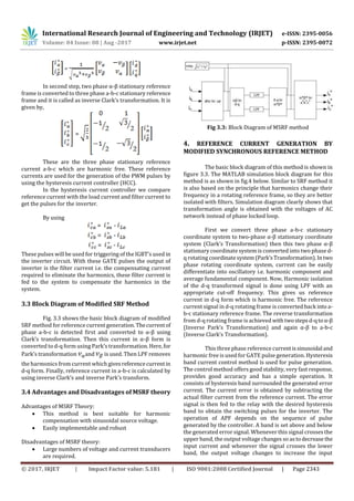
Fig. 5.2: FFT analysis of source current with MSRF theory
REFERENCES
[1] Bhim Singh, J. Solanki, “A Comparison of Control
Algorithms for DSTATCOM”, IEEE Transactions on
Industrial Electronics, VOL. 56, NO. 7, Page(s): 2738 –
2745, JULY 2009.
[2] A. Bhattacharya, C. Chakraborty and S. Bhattacharya,
“ShuntCompensation,Reviewing Traditional Methodsof
Reference Current Generation”, IEEE Industrial
Electronics Magazine, Sept. 2009.
[3] Akagi H., Kanazawa Y., Nabae A.,“Instantaneousreactive
power compensation comprising switching devices
without energy storage components”, IEEE Trans. Ind.
Appl., vol. IA-20, 2010, pp- 625-630.
[4] Chen Duo, Chen Xincan, Kang Mingcai, “An Analysis on
Sequence of the Harmonic in Power System”, China
International Conference on Electricity Distribution
(CICED 2014).
[5] P. Santiprapan and K-L. Areerak, “Performance
Improvement ofHarmonic DetectionusingSynchronous
Reference Frame Method”, International Conference on
Advances in Energy Engineering 2010.
[6] Nilesh M. Chamat, Prof. S. P. Diwan, Vikas S. Bhandare
and Snehal Jamadade, “Instantaneous Reactive Power
Theory for Real Time Control of Three-Phase Shunt
Active Power Filter (SAPF),” 2014 International
Conference on Circuit, Power and Computing
Technologies [ICCPCT], IEEE, pp. 792- 796.
[7] P. Salmerón and S. P. Litrán, “Improvement of the
Electric Power Quality Using Series Active and Shunt
Passive Filters”, IEEE Transactions on Power Delivery,
Vol. 25, April 2010, pp. 1058-1067.
[8] SQUARE D Product Data Bulletin, Power System
Harmonics Causes and Effects of Variable Frequency
Drives Relative to the IEEE 519-1992 Standard, Bulletin
No. 8803PD9402, August, 1994.
BIOGRAPHIES
Mr. Bhushan S. Rakhonde
He received Bachelor of
Engineering degree in Electrical
Engineering. pursuing Master of
Engineering in Electrical Power
System Engineering, G.H.R.C.E.M.
Amravati, Maharashtra, India
Mr. C. M. Bobade
Assistant Professor & H.o.D.
Electrical EngineeringDepartment,
G.H.R.C.E.M. Amravati,](https://image.slidesharecdn.com/irjet-v4i8420-170927091720/85/Harmonic-Mitigation-using-Modified-Synchronous-Reference-Frame-Theory-6-320.jpg)

This document summarizes a research paper that presents a new control algorithm called the Modified Synchronous Reference Frame (MSRF) Theory to generate reference currents for a three-phase shunt active power filter (SAPF) to mitigate harmonics in power systems. The SAPF injects compensating currents to cancel out harmonic currents from nonlinear loads, making the source current sinusoidal. The MSRF method calculates the transformation angle from the AC network voltages rather than a phase-locked loop, allowing it to better isolate harmonics. Simulation results showed the SAPF reduced the total harmonic distortion to 3.25% using the MSRF control algorithm. Passive filters are limited and can cause resonance, while the SAPF


