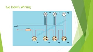
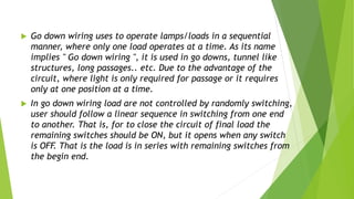
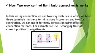
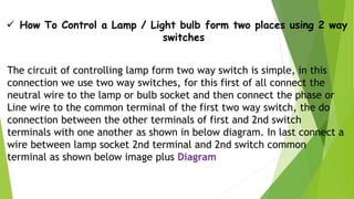
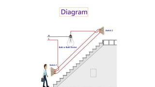
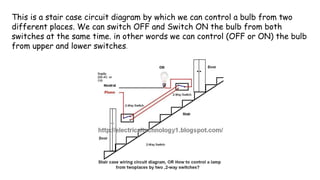
Electrical workshop
Types of wiring
(Staircase wiring & Ground wiring)
Mahatma Gandhi Institute Of Technical
Education And Research Center
PRESENTED BY :
ENROLLMENT NO NAME
 160330109xxx Vaibhav Tandel
BRANCH : ELECTRICAL ENGINEERING
SUBJECT : ELECTRICAL WORKSHOP
Staircase wiring
How to Control a Lamp / Light Bulb from Two places Using Two Way
switches For Staircase Lighting Circuit
 Why Two way light switch wiring is important in Staircase circuit
Staircase circuit connection wiring is different form one way control
light switch and we did not use one way switches in this connection
because we need to controlled or switch off/on the lamp form both
places top and down. For that we control lamp form two places using
two way switches. In short this connection we use to save energy and to
control or switching lamp / light bulb form both places
 How Two way control light bulb connection is works
In this wiring connection we use two way switches in which we have
three terminals, in these terminals one is common and two for
connection. we can use it for many connection using different
connection methods. For example we use it changing flow of
current positive to negative etc.
 How To Control a Lamp / Light bulb form two places using 2 way
switches
The circuit of controlling lamp form two way switch is simple, in this
connection we use two way switches, for this first of all connect the
neutral wire to the lamp or bulb socket and then connect the phase or
Line wire to the common terminal of the first two way switch, the do
connection between the other terminals of first and 2nd switch
terminals with one another as shown in below diagram. In last connect a
wire between lamp socket 2nd terminal and 2nd switch common
terminal as shown below image plus Diagram
Diagram
This is a stair case circuit diagram by which we can control a bulb from two
different places. We can switch OFF and Switch ON the bulb from both
switches at the same time. in other words we can control (OFF or ON) the bulb
from upper and lower switches.
Tube light Wiring
Tube light is not connected in the supply main directly. Although it operates
at 230 V, 50 Hz, some auxiliary electrical components are used to insert in
this installation to support the tube light operational principle. The total
electrical components for single tube light installation are
 Choke: it is electromagnetic ballast or electronic
ballast.
 Starter: Small neon glow up lamp
 Switch
 Wires
 Wiring Diagram of Single Tube Light Installation with
Electromagnetic Ballast
 How to Install a Single Tube Light with Electromagnetic Ballast
 From the junction box the neutral wire is not taken out to the switch board, rather it is taken
out from the junction box and carried out to the port 2 of the tube light, as per figure above. A
wire connects port 2 and pin 1 of the terminal 2 already. So the neutral wire is continued from
port 2 to pin 1 of terminal 2.
 The live wire or phase is taken from the junction box to the switch board. The live wire is
connected to the one terminal of the switch. From another terminal of the switch the wire is
carried out up to tube light set up and connected to port 1.
 One terminal of choke or ballast is connected to port 1 and another terminal is connected to
pin 1 of terminal 1.
 One end of a starter is connected to pin 2 of terminal 1 and another end of the starter is
connected to the pin 2 of terminal 2.
 As no starter is used in case of electronic ballast application, wiring
diagram is little bit changed.
 Electronic ballast has six ports, two ports out of six ports are for input
and rest four ports are for output ports. Suppose they are named port 1
and port 2 for input; port 3, port 4, port 5 and port 6 are for output of
the ballast.
 From the junction box the neutral wire is taken out from the junction box
and carried out to the port 2 of the electronic ballast to connect, as per
figure above.
 The live wire or phase is taken from the junction box to the switch board.
The live wire is connected to the one terminal of the switch. From
another terminal of the switch, the wire is carried out up to tube light set
up and connected to port 1 of the electronic ballast.
•Let, the color of wires from port 3 and port 4 are black, and from port 5 and port
6 are red or any other color.
•Port 3 and pin 2 of terminal 1 and Port 4 and pin 1 of terminal 1 are connected.
•Port 6 and pin 2 of terminal 2 and Port 5 and pin 1 of terminal 2 are connected.
[NB: incoming voltage of port 1 and port 2 of the electronic ballast is only 230 V,
50 Hz. But output ports 3, 4, 5 and 6 give very high voltage at the time of switch
ON, may be 1000 V at 40 kHz or more. When tube light starts to operate, output
ports voltages become below 230 V at 40 kHz or more.]
Go Down Wiring
 Go down wiring uses to operate lamps/loads in a sequential
manner, where only one load operates at a time. As its name
implies " Go down wiring ", it is used in go downs, tunnel like
structures, long passages.. etc. Due to the advantage of the
circuit, where light is only required for passage or it requires
only at one position at a time.
 In go down wiring load are not controlled by randomly switching,
user should follow a linear sequence in switching from one end
to another. That is, for to close the circuit of final load the
remaining switches should be ON, but it opens when any switch
is OFF. That is the load is in series with remaining switches from
the begin end.
Godown wiring makes the feasibility for the user to turn off the
load when switching another, its circuit arrangement is in such a way
that, from common pole we can switch to both 1 & 2 poles, the 1st
pole is connected to load and 2nd to common pole of next and this
sequence repeat. In godown wiring as the remaining switches are in
position common to the 2nd pole (c-2) then it is in contact with the
common pole of next switch by this arrangement we can connect
infinite number of loads and switching one load OFF previous load
and ON next.
Switch S1 in the circuit is SPST (single pole single throw) and
remaining are SPDT (single pole double throw). In godown wiring the
number of loads can be connected further to any extend.
Thank you

Staircase wiring & ground wiring

  • 1.
    Electrical workshop Types ofwiring (Staircase wiring & Ground wiring) Mahatma Gandhi Institute Of Technical Education And Research Center
  • 2.
    PRESENTED BY : ENROLLMENTNO NAME  160330109xxx Vaibhav Tandel BRANCH : ELECTRICAL ENGINEERING SUBJECT : ELECTRICAL WORKSHOP
  • 3.
  • 4.
    How to Controla Lamp / Light Bulb from Two places Using Two Way switches For Staircase Lighting Circuit  Why Two way light switch wiring is important in Staircase circuit Staircase circuit connection wiring is different form one way control light switch and we did not use one way switches in this connection because we need to controlled or switch off/on the lamp form both places top and down. For that we control lamp form two places using two way switches. In short this connection we use to save energy and to control or switching lamp / light bulb form both places
  • 5.
     How Twoway control light bulb connection is works In this wiring connection we use two way switches in which we have three terminals, in these terminals one is common and two for connection. we can use it for many connection using different connection methods. For example we use it changing flow of current positive to negative etc.
  • 6.
     How ToControl a Lamp / Light bulb form two places using 2 way switches The circuit of controlling lamp form two way switch is simple, in this connection we use two way switches, for this first of all connect the neutral wire to the lamp or bulb socket and then connect the phase or Line wire to the common terminal of the first two way switch, the do connection between the other terminals of first and 2nd switch terminals with one another as shown in below diagram. In last connect a wire between lamp socket 2nd terminal and 2nd switch common terminal as shown below image plus Diagram
  • 7.
  • 8.
    This is astair case circuit diagram by which we can control a bulb from two different places. We can switch OFF and Switch ON the bulb from both switches at the same time. in other words we can control (OFF or ON) the bulb from upper and lower switches.
  • 9.
  • 10.
    Tube light isnot connected in the supply main directly. Although it operates at 230 V, 50 Hz, some auxiliary electrical components are used to insert in this installation to support the tube light operational principle. The total electrical components for single tube light installation are  Choke: it is electromagnetic ballast or electronic ballast.  Starter: Small neon glow up lamp  Switch  Wires
  • 11.
     Wiring Diagramof Single Tube Light Installation with Electromagnetic Ballast
  • 12.
     How toInstall a Single Tube Light with Electromagnetic Ballast  From the junction box the neutral wire is not taken out to the switch board, rather it is taken out from the junction box and carried out to the port 2 of the tube light, as per figure above. A wire connects port 2 and pin 1 of the terminal 2 already. So the neutral wire is continued from port 2 to pin 1 of terminal 2.  The live wire or phase is taken from the junction box to the switch board. The live wire is connected to the one terminal of the switch. From another terminal of the switch the wire is carried out up to tube light set up and connected to port 1.  One terminal of choke or ballast is connected to port 1 and another terminal is connected to pin 1 of terminal 1.  One end of a starter is connected to pin 2 of terminal 1 and another end of the starter is connected to the pin 2 of terminal 2.
  • 13.
     As nostarter is used in case of electronic ballast application, wiring diagram is little bit changed.  Electronic ballast has six ports, two ports out of six ports are for input and rest four ports are for output ports. Suppose they are named port 1 and port 2 for input; port 3, port 4, port 5 and port 6 are for output of the ballast.  From the junction box the neutral wire is taken out from the junction box and carried out to the port 2 of the electronic ballast to connect, as per figure above.  The live wire or phase is taken from the junction box to the switch board. The live wire is connected to the one terminal of the switch. From another terminal of the switch, the wire is carried out up to tube light set up and connected to port 1 of the electronic ballast.
  • 14.
    •Let, the colorof wires from port 3 and port 4 are black, and from port 5 and port 6 are red or any other color. •Port 3 and pin 2 of terminal 1 and Port 4 and pin 1 of terminal 1 are connected. •Port 6 and pin 2 of terminal 2 and Port 5 and pin 1 of terminal 2 are connected. [NB: incoming voltage of port 1 and port 2 of the electronic ballast is only 230 V, 50 Hz. But output ports 3, 4, 5 and 6 give very high voltage at the time of switch ON, may be 1000 V at 40 kHz or more. When tube light starts to operate, output ports voltages become below 230 V at 40 kHz or more.]
  • 15.
  • 16.
     Go downwiring uses to operate lamps/loads in a sequential manner, where only one load operates at a time. As its name implies " Go down wiring ", it is used in go downs, tunnel like structures, long passages.. etc. Due to the advantage of the circuit, where light is only required for passage or it requires only at one position at a time.  In go down wiring load are not controlled by randomly switching, user should follow a linear sequence in switching from one end to another. That is, for to close the circuit of final load the remaining switches should be ON, but it opens when any switch is OFF. That is the load is in series with remaining switches from the begin end.
  • 17.
    Godown wiring makesthe feasibility for the user to turn off the load when switching another, its circuit arrangement is in such a way that, from common pole we can switch to both 1 & 2 poles, the 1st pole is connected to load and 2nd to common pole of next and this sequence repeat. In godown wiring as the remaining switches are in position common to the 2nd pole (c-2) then it is in contact with the common pole of next switch by this arrangement we can connect infinite number of loads and switching one load OFF previous load and ON next. Switch S1 in the circuit is SPST (single pole single throw) and remaining are SPDT (single pole double throw). In godown wiring the number of loads can be connected further to any extend.
  • 18.