Download to read offline
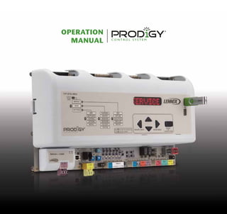
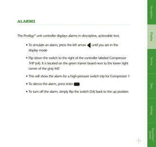
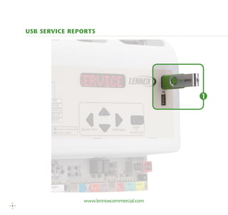
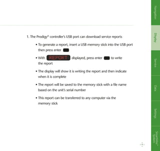
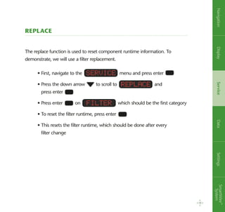
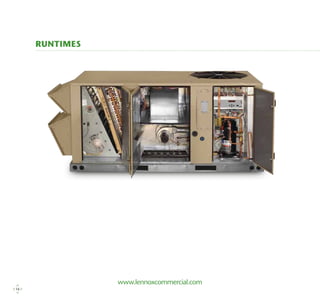
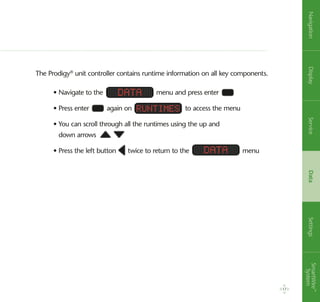
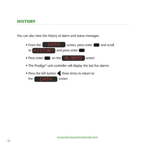
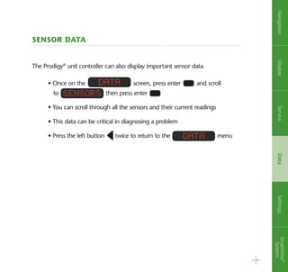
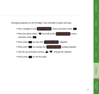
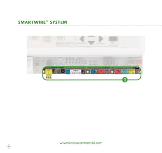

The document provides an overview of the Prodigy control system used on Lennox rooftop units. It describes the key components of the Prodigy system, including the controller, SmartWire system, and optional modules. It then outlines various functions of the Prodigy controller such as navigation, display features, alarms, service reports, profiles, self-test, replacing components, viewing runtimes, sensors, and changing setpoints.