Downloaded 41 times
![PROGRAMMING OVERVIEW
You can program the system at any time, even at the installer's premises prior to the actual installation. Programming can
also be performed remotely from the installer’s office/home, using an IBM personal computer, a modem, and Compass
downloading software.
TO ENTER PROGRAMMING MODE:
Local programming requires the use of an alpha keypad connected to the keypad terminals on the control.
A. POWER UP, then depress [,] and [#] both at once, within 50 seconds of powering up (if ,98 was used to exit previously,
this method must be used to reenter program mode). OR
B. Initially, key: Installer Code (4 + 1 + 1 + 2) plus 8 + 0 + 0.
Data Field Programming Procedures
Task Procedure
Go to a Data Field Press [∗] + [Field Number], followed by the required entry.
Entering Data When the desired field number appears, simply make the required entry. When the last entry for a
field is entered, the keypad beeps three times and automatically displays the next data field in
sequence. If the number of digits that you need to enter in a data field is less than the maximum digits
available (for example, the phone number fields *41, *42), enter the desired data, then press [∗ ] to
end the entry. The next data field is displayed.
Review a Data Field Press [#] + [Field Number].
Data will be displayed for that field number. No changes will be accepted in this mode.
Deleting an Entry Press [∗] + [Field Number] + [∗]. (Applies only to fields ∗40–*44, *94, and pager programming fields)
Interactive Menu Mode Programming (∗29, ∗56, ∗57, ∗58, ∗79, ∗80, ∗81, ∗82)
∗
See respective sections in this document for programming procedures.
Press [,] + [Menu Mode No.] (for example, ,56). The alpha display keypad will display the first of a series of prompts.
The following is a list of the various Programming modes used to program this system:
Programming Mode… Used to …
Data Field Programming Program basic data fields used for setting the various system options.
Most of the data fields in this system have been programmed for specific default
values. However, some fields must be programmed for each particular
installation to establish its specific alarm and reporting features.
∗29 IP/GSM Programming Program the IP and/or GSM options from a keypad.
∗56 Zone Programming Assign zone characteristics, report codes, alpha descriptors, and serial numbers
for 5800 RF transmitters.
∗57 Function Key Programming Program each of the four alphabet function keys to perform one of several
system operations.
∗58 Zone Programming Assign zone attributes similar to ∗56 mode, but provides a faster programming
(Expert Mode) procedure and is intended for those more experienced in programming controls
of this type.
∗79 Output Device Mapping Assign device address of the 4204 Relay module and map the specific relays
∗80 Output Definitions Define up to 12 output definitions which can control the output relays mapped
using *79 Output Device Mapping mode.
∗81 Zone List Programming Create Zone Lists for relay zones, chime, night-stay, cross zones, and pager
zones.
∗82 Alpha Programming Create alpha descriptors for easy zone identification.
Scheduling Mode (code + [#] +64) Create schedules to automate various system functions.
Site-Initiated Download Installer code + [#] + 1 (perform while system is disarmed and in normal mode)
INITIALIZE DOWNLOAD and RESET DEFAULTS
,96 Press ∗96 while in Program Mode. This initializes the system for downloading and resets all the subscriber account
numbers and CSID.
,97 Press ∗97 while in Program Mode. This resets all data fields to the default values shown on the Program Form. Use
∗97 only if you wish to return to the original factory-programmed defaults. Do not press ∗97 to load defaults if any
programming has been done previously—data already programmed into the system will be changed!
TO EXIT PROGRAMMING MODE:
,98 Exits programming mode and prevents re-entry by: Installer Code + 8 + 0 + 0. If ,98 is used to exit programming
mode, system must be powered down, and method A above used to enter the programming mode.
See field *88 for other *98 Program mode lockout options.
,99 Exits programming mode and allows re-entry by: Installer Code + 8 + 0 + 0 or method A above.
SPECIAL MESSAGES
OC = OPEN CIRCUIT (no communication between Keypad and Control).
EE or ENTRY ERROR = ERROR (invalid field number entered; re-enter valid field number).
After powering up, AC, dI (disabled) or Busy Standby and NOT READY will be displayed after approximately 4 seconds.
This will revert to a “Ready” message in approximately 1 minute, which allows PIRS, etc. to stabilize. You can bypass this
delay by pressing [#] + [0].
If E4 or E8 appears, more zones than the expansion units can handle have been programmed. The display will clear after
you correct the programming.
–3–](https://image.slidesharecdn.com/honeywell-vista-10p-programming-guide-120917000741-phpapp01/85/Honeywell-vista-10p-programming-guide-3-320.jpg)
![DATA FIELD PROGRAMMING FORM
Where noted, certain fields have special settings when used with the VISTA-10PSIA (indicated by heavy borders and reverse type throughout
for easy identification).
SIA Guidelines: Notes in certain data fields give instructions for programming the VISTA-10P for False Alarm Reduction.
NOTE: Entry of a number other than one specified will give unpredictable results. Values shown in brackets are factory defaults.
∗20 Installer Code [4112] | | | ∗32 Fire Alarm Sounder Timeout [0]
4 digits, 0–9. Can perform all system functions except 0 = sounder stops at timeout programmed in field ∗33
cannot disarm unless it is used to arm system. 1 = no sounder timeout UL: must be “1” for fire install.
Select whether or not alarm sounding continues until
∗21 Quick Arm Enable [0]
manually turned off (ignores sounder timeout). If not
0 = no quick arm; 1 = allow quick arm (with [#] key) selected, sounding stops at timeout programmed in ∗33.
Select whether or not users can press the [#] key in place of This control complies with NFPA requirements for temporal
entering a security code when arming the system (e.g., to pulse sounding of fire notification appliances. Temporal
arm AWAY, press [#] + AWAY). If not selected, users must pulse sounding for a fire alarm consists of the following:
enter a security code to arm the system. In either case, the 3 pulses – pause – 3 pulses – pause – 3 pulses.
user code is always needed to disarm the system.
∗22 RF Jam Option [0]
∗33 Alarm Sounder (Bell) Timeout [1]
0 = none; 1 = 4 min; 2 = 8 min; 3 = 12 min; 4 = 16 min
0 = no RF Jam detection
1 = send RF Jam report upon detection of RF jamming signal UL: For residential fire alarm installation, must be set for a
Select whether or not the system sends an RF jam report if minimum of 4 min (option 1); for UL Commercial Burglary
an RF jamming signal is detected. installations, must be minimum 16 min (option 4)
UL: must be 1 if wireless devices are used Enter the desired alarm sounding time. Entering “0” lets
sounding continue until manually turned off.
∗23 Quick (Forced) Bypass [0]
∗34 Exit Delay [60] |
0 = no quick bypass UL: must be “0”
00 - 96 = 0 - 96 secs; 97 = 120 secs
1 = allow quick bypass (code + [6] + [#] )
SIA Guidelines: minimum exit delay is 45 seconds
Select whether or not the Quick Bypass command (code
+[6] + [#]) is active. Zones bypassed by this function will be
displayed after the bypass is initiated. VISTA-10PSIA: 45 - 96 = 45 - 96 secs; 97 = 120 secs
NOTE: Entries less than 45 will result in a 45-second delay.
∗24 RF House ID Code [00] |
Enter the desired time the system waits before arming
00 = disable all wireless keypad usage entry/exit zones. If the entry/exit door is left open after this
01–31 = house ID for 5827, 5827BD or 5804BD keypad time expires, an alarm will occur.
Enter the RF House ID, which identifies receivers and UL installations: For UL Commercial Burglar Alarm and UL
wireless keypads. If a 5827 or 5827BD Wireless Keypad or Residential Burglar Alarm installations with line security,
5804BD Transmitter is being used, a House ID code must total exit time must not exceed 60 seconds.
be entered, and the keypad set to the same House ID.
∗26 Chime By Zone [0]
∗35 Entry Delay #1 (zone type 01) [30] |
00 - 96 = 0 - 96 secs; 97 = 120 secs; 98 = 180 secs;
0 = no (chimes on fault of any entry/exit or perimeter zone
99 = 240 secs
when chime mode on);
SIA Guidelines: minimum entry delay is30 seconds
1 = use zone list (chimes on fault of specific zones
programmed in chime zone list 3 when Chime mode on; VISTA-10PSIA:
use *81 Menu mode to select zones) 30-96 = 30 - 96 secs; 97 = 120 secs; 98 = 180 secs;
Select if you want a list of specific zones to chime when 99 = 240 secs
faulted while the system is in Chime mode (use zone list 3 to NOTE: Entries less than 30 will result in a 30-second delay.
assign these zones; see ∗81 Zone List Programming section
for details). If not selected, all entry/exit and perimeter zones For UL Residential Burglary Alarm installations, must be
will chime when faulted and system is in Chime mode. set for a maximum of 30 seconds; entry delay plus dial
delay should not exceed 1 min. For UL Commercial
∗28 Access Code For Phone Module [00] |
Burglar Alarm, total entry delay may not exceed 45
00 = disable; UL: must be “00” for UL Commercial Burg. inst. seconds.
1st digit: enter 1–9; 2nd digit: enter # + 11 for ",", Enter the desired time within which the system must be
or # + 12 for "#". disarmed after opening an entry door. If this time expires
Enter a 2-digit access code for the 4286 Phone Module, if without disarming, an alarm occurs.
used. Example: If desired access code is 7∗ , 7 is the first
entry, and [#] + 11 (for ∗) is the second entry. ∗36 Entry Delay #2 (zone type 02) [30] |
NOTE: A “0” in either digit disables the phone module. See *35 Entry Delay 1 above for entries.
Use this entry for a secondary entry door. See *35 above for
∗29 Enable IP/GSM – Communication Device Menu explanation.
Mode (pass-through programming)
This is a Menu Mode command, not a data field. ∗37 Audible Exit Warning [1]
See ∗29 Menu Mode section later in this document.
0 = no; 1 = yes; SIA Guidelines: must be enabled (enter 1)
∗31 One Audible Alarm Per Zone [0] VISTA-10PSIA: Feature always enabled; field does not exist.
0 = unlimited sounding Select whether or not you want exit warning sounds, which
1 = one alarm sounding on bell output per zone consist of slow continuous beeps until the last 10 seconds,
then it changes to fast beeps. Sound ends when exit time
VISTA-10PSIA: If “0” selected, “alarm sounding per zone”
expires.
will be the same as the “number of reports in armed period”
set in field *93 (1 if one report, 2 if 2 reports, unlimited for
zones in zone list 7).
Select whether or not the system limits alarm sounding to
once per arming period for a given zone.
–4–](https://image.slidesharecdn.com/honeywell-vista-10p-programming-guide-120917000741-phpapp01/85/Honeywell-vista-10p-programming-guide-4-320.jpg)
![∗38 Confirmation Of Arming Ding [0] ∗43 Primary Subs. Acct. No.
0 = no ding | | | / | | | | | [FFFF/FFFFFF]
1 = confirmation ding after arming system Enter 4 or 10 digits, depending on selection in *48 Report
2 = ding after arming from RF button or RF keypad only Format. See box above for entries. To clear, press *43*.
(except 5827/5827BD) Enter the primary subscriber account number.
UL: must be “1” for UL Commercial Burglar Alarm inst.
Select whether and when you want a confirmation of arming
∗44 Secondary Subs. Acct. No.
“ding” (1/2 second external sounder “ding”). | | | / | | | | | [FFFF/FFFFFF]
If “1” selected, ding occurs when closing report is sent, or at
See *43. To clear, press *44*.
the end of Exit Delay.
Enter the secondary subscriber account number
If “2” selected, ding occurs upon reception of the wireless
arming command. ∗47 Phone System Select [1]
∗39 Power Up In Previous State [1] DIALING NOT On WATS LINE USING WATS LINE
Pulse Dial 0 2
0 = always power-up in a disarmed state
Tone Dial 1 3
1 = assume the system status prior to power down
Select whether the system will be using pulse or tone
UL: must be “1” SIA Guidelines: must be enabled (enter 1)
dialing, and whether it is on a WATS line.
VISTA-10PSIA: Feature must be enabled (enter 1). ∗48 Report Format [77]
Select whether or not the system powers up in its previous 0 = 3+1, 4+1 ADEMCO L/S STANDARD Primary Second
state (if the system powers up armed and a zone is faulted, 1 = 3+1, 4+1 RADIONICS STANDARD
an alarm will occur 1 minute after power up). Note that if the 2 = 4+2 ADEMCO L/S STANDARD
previous state was armed Away or Stay, the system ignores 3 = 4+2 RADIONICS STANDARD
sensor changes for 1 minute, which allows time for sensors 5 = 10-digit ADEMCO CONTACT ID® REPORTING
such as PIRs to stabilize. 6 = 4+2 ADEMCO EXPRESS
7 = 4-digit ADEMCO CONTACT ID® REPORTING
DIALER PROGRAMMING 8 = 3+1, 4+1 ADEMCO L/S EXPANDED
Enter the number of digits shown. Do not fill unused spaces. Enter 9 = 3+1, 4+1 RADIONICS EXPANDED
0–9; #+11 for ','; #+12 for '#'; #+13 for a 2-second pause. If fewer Select the desired type of reports to be sent to the
than the maximum digits entered, exit the field by pressing [∗]. The primary/secondary numbers. Make selection from the table
next field number is displayed. in the Programming Guide. If “0” selected, all reports go only
∗40 PABX Access Code | | | | | to the primary number unless unsuccessful, then control will
attempt to dial secondary number.
Enter up to 6 digits. To clear entries, press ,40,. If call
waiting used, enter its cancel digits “∗ (#+11) 70” plus “# + ∗49 Split/Dual Reporting [0]
13” (pause). 0 = Standard/Backup reporting only (all to primary unless fail)
NOTES: See Backup Reporting note below.
1. The call waiting disable feature cannot be used on a PABX
Primary Phone No. Secondary Phone No.
line.
1 = Alarms, Restore, Cancel Others
2. Using call waiting cancel on a non-call waiting line will prevent
2 = All except Open/Close, Test Open/Close, Test
successful communication to the central station.
3 = Alarms, Restore, Cancel All
VISTA-10PSIA: If call waiting is used, enter call waiting 4 = All except Open/Close, Test All
disable digits as described above, and also set Call Waiting 5 = All All
Disable option in field *91. Backup Reporting: All reports are sent only to the primary
number unless unsussessful after 8 attempts. If unsuccessful,
Enter the PABX code, if used. If fewer than 6 digits, exit by the system makes up to 8 attempts to send all reports to the
pressing [∗], which advances to the next field. secondary number. If still unsuccessful after 16 attempts, the
Call Waiting: If the subscriber’s phone service has “call system displays “COMM FAILURE” message (FC for fixed-
waiting” (and is not using PABX), enter “*70” (“# + 11”) plus “# word keypads). Backup reporting is automatic only if there is
+ 13” (pause) as the PABX entry to disable “call waiting” a secondary phone number (field ∗42)
during control panel calls. If the subscriber does not have “call
waiting” and is not using PABX, make no entry in this field. ∗50 Burglary Dialer Delay [2, 0]
Important: 1. The call waiting disable feature cannot be Delay Time: Delay Time VISTA-10PSIA
used on a PABX line. 2. Using Call Waiting Disable on a 0 = no delay UL: must be “0” Delay Disable
non-call waiting line will prevent successful communication 1 = 15 seconds; 2 = 30 seconds; 3 = 45 seconds
to the central station. SIA Guidelines: delay must be minimum of 15 seconds
∗41 Primary Phone No. VISTA-10PSIA:
| | | | | | | | | | | | | | | | | | | Delay Time: 1 = 15 secs; 2 = 30 secs; 3 = 45 secs
Delay Disable:
∗42 Secondary Phone No. 0 = use delay set in entry 1
| | | | | | | | | | | | | | | | | | | 1 = dial delay disabled for zones listed in zone list 6 (use
zone list 6 to enter those zones that require dial delay
Enter up to 20 digits. To clear entries, press ,41, or ,42,
to be disabled; these zones ignore the setting in entry
respectively.
1)
Enter the primary phone and secondary phone numbers. If
you enter fewer than 20 digits, exit by pressing [∗]. To clear UL: Dial delay plus entry delay must not exceed one minute;
use zone list 6 to disable dial delay from appropriate zones,
entries from field, press ∗41∗.
if necessary.
NOTE: Entry of a number other than one specified will give
unpredictable results. Enter the desired delay time (none, 15, 30, or 45 seconds)
before a “BURGLARY ALARM” report is sent to the central
For fields *43- *44: Enter 0–9; #+11 for B; #+12 for C; #+13 for D;
station. This delay allows time for the subscriber to avoid
#+14 for E; #+15 for F. Enter [,] as the fourth digit if a 3-digit sending a false alarm if the alarm was inadvertently caused.
account number (for 3+1 dialer reporting format) is used. Enter 0 as This delay does not apply to zone type 24 alarms (silent
the first digit of a 4-digit account number for Nos. 0000-0999. Exit burglary) or to 24-hour zone types 6, 7, and 8 (silent panic,
field by pressing , (and press next field number) if only 3 digits are audible alarm, auxiliary alarm), which are always sent as
used. E.g., For Acct. B234, enter: #+11, 2, 3, 4 soon as they occur.
–5–](https://image.slidesharecdn.com/honeywell-vista-10p-programming-guide-120917000741-phpapp01/85/Honeywell-vista-10p-programming-guide-5-320.jpg)
![∗53 SESCOA/Radionics Select [0] ∗59 Exit Error Report Code (continued)
If the system is not disarmed before entry delay expires, an
0 = Radionics (0-9, B-F), and all formats other than SESCOA “EXIT ALARM” message (VISTA-10PSIA: also zone alarm
1 = SESCOA (0-9 only reporting) message) will be sent to the central station if Exit Error
Select whether SESCOA format is used. Report Code is enabled. The keypad will display “EA” (fixed-
word ) or “EXIT ALARM” (alpha display), and alarm
∗54 Dynamic Signaling Delay [0] sounding continues until the system is disarmed (or timeout
Delay selectable from 0 to 225 secs in 15-sec increments. occurs).
0 = no delay (both signals sent); 1 = 15 secs; 2 = 30 secs, etc An Exit Alarm condition will also result if a fault occurs in an
UL: If using line security, must be 0. exit or interior zone within 2 minutes following the end of the
Intended for use with communication device on ECP (ex. exit delay, and an “EXIT ALARM” message will be sent to
LRR) reporting. Enter the desired time the panel should wait, the central station (except for VISTA-10PSIA, see field *69
per message, for acknowledgment from the first reporting Recent Closing report).
destination (see ∗55) before it attempts to send a message
to the second destination. Entering ”0” sends redundant
∗60 Trouble Report Code [10] |
reports to both Primary Dialer and the communication Sent if a zone has a trouble condition.
device. UL: Required for UL commercial burglar alarm installations
and for residential fire alarm installations
∗55 Dynamic Signaling Priority [0] ∗61 Bypass Report Code [00] |
0 = Primary Dialer first; 1 = Communication Device first. Sent when a zone is manually bypassed.
For UL Commercial Burglary installations that use a DACT UL: Required for UL commercial burglar alarm installations.
and LRR, this field must be “0”.
∗62 AC Loss Report Code [10] |
Intended for use with communication device reporting (field Enter the appropriate report code. Timing of this report is
∗29 must be enabled). random with up to a 4-hour delay. If AC restores before the
Select the initial reporting destination for messages as report goes out, there is no “AC LOSS” report.
follows: UL: Required for UL commercial burglar alarm installations
Primary Dialer First selected (0): and for residential fire alarm installations
• If acknowledged before delay expires (see ∗54), then ∗63 Low Bat Report Code [10] |
message will not be sent via communication device.
Sent when a low-battery condition exists in the system’s
• If not acknowledged before delay expires, message is
battery.
sent to both the Primary Phone No. and communication
UL: Required for UL commercial burglar alarm installations
device.
and for residential fire alarm installations
Communication Device (LRR) First selected (1):
• If acknowledged before delay expires, then message will ∗64 Test Report Code [00] |
not be sent to the primary dialer. Sent periodically to test that the communicator and phone
• If not acknowledged before delay expires, then message lines are operational
is sent to both Primary Phone No. and communication Use Scheduling mode to set periodic test reports or use the
device. following key commands to set schedule 2 to the stated
repeat option (first test report sent 12 hours after command):
∗56 -*58 Menu Modes installer code +[#] + [0] + 0 = test report sent every 24 hours
These are Menu Mode commands, not data fields. installer code +[#] + [0] + 1 = test report sent once per week
See Menu Mode sections later in this document. installer code +[#] + [0] + 2 = test report sent every 28 days
Each mode sets schedule 2 to the selected repeat option;
PROGRAMMING SYSTEM STATUS, & RESTORE REPORT first test report sent 12 hours after command.
CODES (∗59 - ∗68, ∗70 - ∗76, and ∗89):
∗ NOTE: Make sure the Real-Time Clock is set to the proper
For 3+1 or 4+1 Standard Format: Enter a code in the first box: 1– time before entering the test report schedule command to
9, #+10 for 0, #+11 for B, #+12 for C, #+13 for D, #+14 for E, #+15 ensure that test reports are sent when expected. (see
for F. Setting the Real-Time Clock section).
A 0 (not #+10) in the first box will disable a report. A 0 (not #+10) in UL: Required for UL commercial burglar alarm installations
the second box will result in automatic advance to the next field. and for residential fire alarm installations
For Expanded or 4+2 Format: Enter codes in both boxes (1st and ∗65 Open Report Code [0]
2nd digits) for 1–9, 0, or B–F, as described above.
A 0 (not #+10) in the second box will eliminate the expanded Enter the appropriate report code, which is sent upon
message for that report. A 0 (not #+10) in both boxes will disable disarming of the system.
the report. UL: Required for UL commercial burglar alarm installations
For Ademco Contact ID® Reporting: Enter any digit (other than 0) ∗66 Arm Away/Stay Rpt Code [0,0]
in the first box, to enable zone to report (entries in the second boxes
are ignored). Enter appropriate report code. Away Stay
A 0 (not #+10) in the first box disables the report. NOTE: “OPEN” reports not sent if associated closing report
UL installations: Program fields *59 - *76 as required by applicable is not enabled
UL Standards shown in each field. ∗67 RF Trans. Low Bat Report Code [00] |
SYSTEM STATUS REPORT CODES Sent when a wireless transmitter low-battery condition
exists.
∗59 Exit Error Report Code [0] UL: must be enabled if wireless devices are used.
See box above for entries. ∗68 Cancel Report Code [00] |
VISTA-10PSIA: [1] Always enabled.
VISTA-10PSIA: [10] Report enabled.
After arming the system, entry/exit and interior zones
Sent upon disarming of the system after an alarm was
remaining open after exit delay expires cause an alarm
reported.
sound at the keypad and external sounder (keypad also
displays “EXIT ALARM”), and entry delay begins. Disarming
before the end of the entry delay stops alarm sounding and
no message is sent to the central station. The keypad
displays “CA” (fixed-word) or “ALARM CANCELED” (alpha
display).
∗59 continued in next column
–6–](https://image.slidesharecdn.com/honeywell-vista-10p-programming-guide-120917000741-phpapp01/85/Honeywell-vista-10p-programming-guide-6-320.jpg)
![∗69 Recent Closing Report Code [11] | ∗84 Auto Stay Arm [1]
0 = no, 1 = yes, auto stay arm enabled
VISTA-10PSIA: Always enabled. Field does not apply to other
If enabled, the system will automatically change AWAY
controls.
mode to STAY mode if the entry/exit door is not opened and
Similar to the Exit Error condition described in field *59, but closed within the exit delay time after a user arms in AWAY
occurs if any burglary zone is faulted within two minutes after mode from a wired keypad (non-RF device). An Opening
the initial exit delay expires. Disarming the system within the report followed by an Armed Stay report is sent to the
two minutes stops the alarm sound and displays " ALARM Central Station.
CANCELED " or "CA" and the faulted zone number. No If the door is opened and closed within the exit delay period,
message is sent to the Central Monitoring Station. the system remains in AWAY mode.
If the system is not disarmed within two minutes, the alarm Any RF device that arms the system AWAY overrides this
sound continues and a “recent closing” and a “zone alarm” feature and the system remains armed AWAY
message are sent to the Central Monitoring Station (after dial
delay expires). ∗85 Cross Zone Timer [0]
This option not for use in UL installations.
0 = 15 seconds 6 = 2-1/2 min #+12 = 8 min
RESTORE REPORT CODES 1 = 30 seconds 7 = 3 min #+13 = 10 min
∗70 Alarm Restore Rpt Code [0] 2 = 45 seconds 8 = 4 min #+14 = 12 min
3 = 60 seconds 9 = 5 min #+15 = 15 min
Sent when an alarm zone is restored to its non-faulted 4 = 90 seconds #+10 = 6 min
condition. 5 = 2 minutes #+11 = 7 min
UL: Required for UL commercial burglar alarm installations Assign cross zones on zone list 4, with *81 Menu mode.
and for residential fire alarm installations NOTE: Cross zoning takes effect only after Exit Delay expires.
∗71 Trouble Restore Rpt Code [00] | Select the maximum amount of time in which two cross
zones must be tripped in an armed system to send an alarm
Sent when a trouble in a zone is restored and code + OFF message to the Central Station. If only one cross zone is
performed. tripped during this time, a trouble message (CID code 380)
UL: Required for UL commercial burglar alarm installations. for that zone is sent to the Central Station.
∗72 Bypass Restore Rpt Code [00] | ∗86 Cancel Verify Keypad Display [1]
Sent when a zone that has been bypassed is unbypassed. 0 = no, 1 = yes
UL: Required for UL commercial burglar alarm installations Select whether “ ALARM CANCELED” is displayed on the
∗73 AC Restore Rpt Code [00] | LCD keypad under the following conditions:
• After the kissoff of the cancel message to the Central
Sent after AC power has been restored after an AC power Station, indicating a successful transmission.
outage.
UL: Required for UL commercial burglar alarm installations • When an alarm is successfully canceled before the
and for residential fire alarm installation Central Station received the Alarm message. E.g., if an
alarm is incorrectly triggered and the user presses code +
∗74 Low Bat Restore Rpt Code [00] | OFF before the dial delay time has expired, the message
will never go out to the CS.
Sent after a system low-battery condition is restored to
normal. • When the Cancel report is not enabled and the system is
UL: Required for UL commercial burglar alarm installations disarmed:
and for residential fire alarm installations a. before dialer delay expires (alarm report not sent)
message “Alarm Canceled” is displayed.
∗75 RF Trans. Lo Bat Rst Rpt Code [00] | b. after dialer delay expires message “Alarm Canceled”
is not displayed.
Sent when a trans. low battery is restored (new battery
installed). ∗87 Misc. Fault Delay Time [0]
UL installations: must be enabled if wireless devices are (used with Configurable Zone Type “digit 6”)
used. Required for UL commercial burglar alarm 0 = 15 seconds 6 = 2-1/2 min #+12 = 8 min
installations and required for residential fire alarm 1 = 30 seconds 7 = 3 min #+13 = 10 min
installations. 2 = 45 seconds 8 = 4 min #+14 = 12 min
∗76 Test Restore Rpt Code [00] | 3 = 60 seconds 9 = 5 min #+15 = 15 min
Sent when the Test mode is exited or upon timeout (4 hrs). 4 = 90 seconds #+10 = 6 min
UL: Required for UL commercial burglar alarm installations 5 = 2 minutes #+11 = 7 min
and for residential fire alarm installations UL: may only be used on non-burglar alarm/ non-fire alarm
zones when used in fire and/or UL burglar alarm
OUTPUT AND SYSTEM SETUP installation
∗77 Daylight Savings Time [3][11] | Enter the desired fault delay time. Used with zones assigned
to a configurable zone type with fault delay on (configurable
Start/End Month zone type digit “6”), and sets a zone response time of 15
0 = Disabled; 1-9 = January-September (1 = Jan, 2 = Feb, etc) seconds to 15 min. It can be assigned to zones with sensors
#+10 = October; #+11 = November; #+12 = December that provide a trouble indication when an oil tank is low, or
Enter the start and end month for daylight savings time, if similar applications for critical condition monitoring where a
applicable to the region. non-alarm response is desired.
∗78 Daylight Savings Time [2][1] | ∗88 Program Mode Lockout Options [0]
Start/End Weekend 0 = standard *98 installer code lockout
0 = disabled, 1 = first, 2 = second, 3 = third (reentry only by [∗] + [#] within 50 seconds after power up)
4 = fourth, 5 = last, 6 = next to last, 7 = third to last 1 = lockout [∗] + [#] reentry after *98 exit
Enter the start and end weekend for daylight savings time, if 2 = not used
applicable to the region. 3 = lockout local programming after *98 exit (reentry by
downloader only)
∗79 -*82 Menu Modes
These are Menu Mode commands, not data fields.
See Menu Mode sections later in this document.
–7–](https://image.slidesharecdn.com/honeywell-vista-10p-programming-guide-120917000741-phpapp01/85/Honeywell-vista-10p-programming-guide-7-320.jpg)
![∗89 Event Log Full Report Code [00] | DOWNLOAD INFORMATION
See box above *59 for report code entries. ∗94 Download Phone No.
Sent when the event log is 80% full (if an event log enable is | | | | | | | | | | | | | | | | | | |
made in field ∗90). If the log becomes full, new messages
overwrite the oldest messages in the log. Enter up to 20 digits, 0–9; #+11 for ','; #+12 for '#'; #+13 for a
2-second pause. Do not fill unused spaces. If fewer than 20
∗90 Event Log Enables [3] digits, exit field by pressing ,. To clear entries, press ,94,.
NOTE:System messages are logged when any non-zero UL: downloading may be performed only if a technician is at
entry is made. the site.
0 = None Enter the downloading computer phone number.
1 = Alarm/Alarm Restore
2 = Trouble/Trouble Restore ∗95 Ring Count For Downloading [15]
4 = Bypass/Bypass Restore; 8 = Open/Close. NOTE: Do not enter “0” if using 4286 Phone Module.
Example: To select “Alarm/Alarm Restore”, and 0 = Disable Station Initiated Download;
“Open/Close”, enter 9 (1 + 8); to select all, enter #15. 1–14 = number of rings (1–9, # +10 =10, # +11 =11,
Select the types of events (up to 32 events) the system # +12 =12, # +13 =13, # +14 =14);
should log. The downloader operator can then upload the 15 = answering machine defeat (# +15 =15).
log and view or print out all or selected categories of the log. Refer to the chart below and program this field accordingly.
The downloader operator can also clear the log. The Event phone answer down-
log can also be viewed at an alpha keypad. The module machine loading Set field ∗95 to…
display/printout at the central station will show the date, yes no no 1-14 (not 0)
time, event, and description of occurrences yes yes no higher than number of rings set on
answer machine (e.g., if ans.
∗91 Option Selection [8, 0] machine is 4 rings, set this field to
5). This allows access to the phone
Options: 0 = None Options VISTA-10PSIA module if the answer machine is
1 = Bell Supervision Processing Call Wait Disable turned off.
NOTE: If Bell Supervision is selected, you must also cut yes no yes 1-14 (not 0)
the red PCB Bell Supervision jumper. yes yes yes 15 (bypasses answer machine†)
4 = AAV UL: must use ADEMCO UVCM module no no no 0
8 = Exit Delay Restart/Reset UL: must be disabled no yes no 0
#+12 = AAV and Exit Delay Restart/Reset no no yes 1-14
SIA Guidelines: Exit Delay should be enabled. no yes yes 15
† NOTE: If “15” is entered to bypass an answering machine, and a 4286 Phone
Module is included in the system, note the following: When calling in from an
VISTA-10PSIA: Options: Same as listed above. off-premises phone, the user should make the initial call, allow 1 or 2 rings
Call Waiting Disable: only, then hang up, then call again. The phone module will now seize the line,
0 = call waiting not used and 2 long tones sound, followed by the usual voice prompt for the access
1 = call waiting disable digits (*70) entered in field *40; code. If this procedure is not followed, phone module operation will not be
possible.
(when selected, the system dials the entry in field
*40 only on alternate dial attempts; this allows proper ∗96, *97 Initialize/Reset Defaults
dialing in the event call waiting service is later
(These are commands, not data fields.)
canceled by the user).
Select the desired options by adding the values of each ∗98, *99 Exit Commands
desired option. (These are commands, not data fields.)
“Exit Delay Restart/reset” option allows use of the [∗] key to PAGER OPTIONS
restart the exit delay at any time when the system is armed The system can send various reports to a pager.
STAY or INSTANT. This feature also enables automatic exit To program pager reporting, do the following:
delay reset, which resets exit delay if the entry/exit door is 1. Enter the appropriate information in the Pager data fields that
re-opened and closed before exit delay time expires after follow.
arming AWAY. Automatic Exit Delay Reset occurs only 2. Enable Pager Delay, if desired, in field *172
once during an armed AWAY period. 3. Make sure appropriate user open/close pager reports are
IMPORTANT: AAV should not be used when Paging or enabled using the user attribute command.
Alarm Reports are sent to a secondary number unless the 4. If using latchkey pager report, define the latchkey report
monitoring zone option is used (which pauses calls). schedule using Scheduling mode (master code + [#] [6] [4] then
Otherwise, the call to the secondary number by the select event type “03”). System must be armed for the Latchkey
communicator after the alarm report will prevent the AAV report to be sent.
from taking control of the telephone line, and the AAV 5. If using a function key to manually send a message to a pager,
“Listen in” session cannot take place. see Function Keys section to program the appropriate function.
6. If reporting zone alarms and troubles to a pager, use *81 Zone
∗93 Reports In Armed Period [1,0] List menu mode to assign the zones associated with each pager
Per Zone (Swinger Suppression) Restrict VISTA-10PSIA
(zone lists 9).
Restrict Report Pairs: Report Pairs Unlimited ∗160 Pager 1 Phone No.
0 = Unlimited Reports Reports Enable
| | | | | | | | | | | | | | | | | | |
1 = 1 report pair
2 = 2 report pairs SIA Guidelines: Must be set for 1 or 2. Enter up to 20 digits. 0–9; #+11 = ','; #+12 = '#'; #+13 = 2-
sec pause.
VISTA-10PSIA: Enter the pager phone number. If you enter fewer than 20
Restrict Report Pairs: 1 = 1 report pair; 2 = 2 report pairs digits, exit by pressing [∗] and next field number. To clear
Unlimited Reports Enable: entries from this field, press ∗160∗
0 = restrict reports to the setting in entry 1
1 = unlimited reports for zones listed in zone list 7; (use
zone list 7 to enter those zones that require unlimited
reporting; these zones ignore the setting in entry 1)
Select the number (0, 1, or 2) of alarm/alarm restore
message pairs per zone allowed to be sent to the central
station in an armed period. Applies to burglary zones only.
–8–](https://image.slidesharecdn.com/honeywell-vista-10p-programming-guide-120917000741-phpapp01/85/Honeywell-vista-10p-programming-guide-8-320.jpg)
![∗161 Pager 1 Characters CONFIGURABLE ZONE TYPE OPTIONS
| | | | | | | | | | | | | | | The system allows you to define a custom zone type, based on the
options described below. This configurable zone types can be
Enter the optional prefix characters, up to 16 digits. programmed via the downloader or from a keypad using data fields
0–9; #+11 = ','; #+12 = '#'; #+13 = 2-second pause. *182-*183 described below.
Enter up to 16 optional characters, which may be sent as a
Configurable Zone Type Options
prefix to the 7-digit system status code sent to Pager 1 (if
used). Phone number in field *160 must be entered. If fewer Auto Restore (entry 2) Faults on zones set for this option are
than 16 characters, exit by pressing [∗] and next field cleared; restore messages sent upon
number. To clear entries from this field, press ∗161∗. restoral of faults.
For example, these optional 16 characters may be Vent Zone (entry 2) Zones set for this option are ignored
composed of the following: if faulted when arming the system,
• paging company PIN number, subscriber account but are protected if the zone is later
number, ∗ (enter # + 11 to send ∗), # (enter # + 12 to send restored (e.g., an open window can
#), pause (enter # + 13 to allow a 2-second pause; some be ignored when arming, but if the
paging systems require pause) window is later closed, it will be
protected; opening the window again
• Any special character(s) the end user may decide to causes an alarm.)
transmit
The format for the 7-digit system status code is defined as Bypass Disarmed (entry 4) Zones set for this option can be
follows: bypassed only while the system is
Pager Format: XXX-YYYY where: disarmed.
XXX = 3-digit event code: 911 = Alarm Bypass Armed (entry 4) Zones set for this option can be
811 = Trouble bypassed when the system is armed.
101 = Opening (disarm) Dial Delay (entry 6) Alarms on zones set for this option
102 = Closing (arm AWAY) participate in dial delay central station
YYYY = 4-digit user or zone number (depending on type reporting, if system dial delay enabled
of event). in field *50.
The first digit is “1,” followed by the 3-digit user or zone
Fault Delay (entry 6) Faults on zones set for this option are
number, or “0,” followed by a 3-digit device address number.
delayed by the time set in field *87.
Example 1. Pager displays: 9 1 1 – 1 0 0 4 : an alarm
Do not use this option if using
(911) caused by a fault in zone 4 (1004).
entry/exit delay for this zone type.
Example 2. Pager displays: 1 0 2 – 1 0 0 5 : a closing–
system arming (102) by User 5 (1005). Faults Display (entry 7) Selects how faults on zones set for
this zone type are displayed.
∗162 Pager 1 Report Options [0]
Power Reset/Verification Selects whether the system resets
0 = no reports sent (entry 7) power (when user enters code +
1 = Opens/closes all users OFF), and whether the system
4 = All alarms and troubles performs alarm verification when a
5 = All alarms / troubles, and opens/closes for all users fault occurs on these zones.
12 = Alarms / troubles for zones entered in zone list 9 Use Entry Delay (entry 8) Selects whether to use the system’s
13 = Alarms / troubles for zones entered in zone list 9, and entry delay times.
opens/closes for all users
Enter the types of reports to be sent to the pager. Use Exit Delay (entry 8) Selects whether to use the system’s
Open/close reports go to pager only when arming exit delay time.
(close)/disarming (open) from a keypad using a security Interior Type (entry 8) Zones set for this option are treated
code; auto-arming/disarming, arming with assigned button, same as standard zone type 4
and keyswitch arming do not send pager messages. (bypasses when armed STAY, faults
displayed).
∗172 Pager Delay Option For Alarms [3]
Alarm Sounds (entry 9) Selects the type of alarms sound for
0 = none, 1 = 1 minute, 2 = 2 minutes, 3 = 3 minutes zones set for this zone type.
Enter the desired pager delay for alarms.
Bell Timeout (entry 9) Alarm sounding on zones set for this
option remain for the duration set in
MISCELLANEOUS SYSTEM FIELDS fields *32/*33.
∗177 Device Duration 1, 2 [0] [0] Fire Zone (entry 9) Zones set for this option respond in
the same manner as if programmed
(used in *80 Menu mode-Device Actions 5/6) 1 2
for zone type 9. Do not set fire zones
0 = 15 seconds 6 = 2-1/2 min #+11 = 7 min to respond as a “fault” in entries 1-6.
1 = 30 seconds 7 = 3 min #+12 = 8 min
2 = 45 seconds 8 = 4 min #+13 = 10 min Trouble Sounds (entry 10) Selects the type of trouble sounds for
3 = 60 seconds 9 = 5 min #+14 = 12 min zones set for this zone type (periodic
4 = 90 seconds #+10 = 6 min #+15 = 15 min beeps = once every 30 seconds;
5 = 2 minutes trouble beeps = rapid beeping).
Enter the desired duration for output action options 5 Chime Enable (entry 10) Zones set for this option cause a
(duration 1) and 6 (duration 2) programmed in ∗80 Output chime when Chime mode is on.
Function Programming.
∗181 60 Hertz AC Operation [0]
0 = 60 Hz; 1 = 50 Hz
Select the type of AC power applied to the control (option is
used for Real-Time Clock synchronization).
–9–](https://image.slidesharecdn.com/honeywell-vista-10p-programming-guide-120917000741-phpapp01/85/Honeywell-vista-10p-programming-guide-9-320.jpg)
![∗182 Configurable Zone Type 90 KEYPAD OPTIONS
To enable keypads:
1. Set desired address at keypad (refer to keypad’s instructions for
1 2 3 4 5 6 7 8 9 10 setting the address). Keypads are identified by predefined
(0-9, #+10=10, #+11=11, #+12=12, #+13=13, #+14=14, addresses (starting at address 16). Options for keypad 1,
#+15=15). address 16, are set by the factory and cannot be changed.
UL: Do not configure zones as a fire alarm or UL burglar 2. Use data field program mode to enable keypad addresses and
alarm zone. enable sound options in fields *190-*196 as shown in the table
above.
Enter the appropriate value for each entry, 1-10, based on
3. Set the following keypad-related data fields as required by the
the charts provided on the next page. Each entry is the
installation: *21 Quick Arm Enable
sum of the values of its selected options
*23 Forced Bypass
To calculate the value for each entry, add the values of the *84 Auto STAY Arm
selected options in each of the entry’s columns shown in NOTE: Each keypad must be assigned a unique address.
the respective chart (one option per column). For example, Keypads programmed with the same address will give
to program entry 2 for “alarm response to short,” “auto unpredictable results.
restore on,” but not a “vent zone,” enter 5 (“1” for alarm
short + “4” for auto restore-yes + “0” for vent zone-no). ∗190 Keypad 2 Device Address 17 [0] [0]
IMPORTANT: Be careful when selecting combinations of Enable: 0 = disabled; 1 = enabled Enable Sound
options for configurable zone types. Contradictory options Sound: 0 = no suppression
can cause unpredictable results. 1 = suppress arm/disarm and E/E beeps
2 = Suppress chime beeps only
3 = suppress arm/disarm, E/E, and chime beeps
∗183 Zone Type 90 Report Codes Select whether or not a keypad is used, and enter the
IMPORTANT: Use existing Contact ID® codes, if desired sound option for the keypad.
appropriate, or define unique codes in CID code range Enable Sound
750-789. See note in installation instructions. ∗191 Keypad 3 Device Address 18 [0] [0]
90 ALARM ID: XXX
TROUBLE ID: XXX ∗192 Keypad 4 Device Address 19 [0] [0]
Enter the desired 3-digit Contact ID® report codes for
alarms and troubles occurring on zones assigned to this ∗193 Keypad 5 Device Address 20 [0] [0]
zone type. Enter the codes sequentially (all 6 digits). When
entering digits, [#] moves cursor back, [∗] moves forward. ∗194 Keypad 6 Device Address 21 [0] [0]
Press [∗] when done to continue.
NOTE: Zone alarm report codes and trouble report code ∗195 Keypad 7 Device Address 22 [0] [0]
(∗60) and relevant restore codes must be enabled in order
to report configurable zone type codes. ∗196 Keypad 8 Device Address 23 [0] [0]
∗197 Exit Time Display Interval [0]
0 = no display; 1-5 = seconds between display refresh
Select whether or not keypads display the exit time
remaining after arming the system, with display updates at
the interval selected (i.e. if the exit delay is 30 seconds and
“2” is selected in this field, the keypad display refreshes
every 2 seconds, displaying 30, 28, 26, 24, etc.).
An interval greater than “1” may be necessary for some
older keypads to allow users time to enter key presses
between display updates.
FIXED-WORD KEYPAD NOTE: If using 2-digit display
keypads (e.g. 6150RF), do not use exit times greater than
the 96-second delay option. Using a longer delay time may
cause end-user confusion because 2-digit display keypads
cannot display times greater than “99.” If longer exit time is
required by the installation, it is recommended that the Exit
Time Display option be disabled (“0”).
∗199 ECP Fail Display [0]
0 = 3-digit display (“1” + device address)
1 = 2-digit fixed-display as “91”
Select the 2-digit or 3-digit ECP Fail display, based on the
type of keypads being used. The 3-digit display option
displays ECP faults as “1” plus the device address (00-30) of
the device causing the fault (e.g., faults on device 07 display
as “107”), and is intended for Alpha keypads and/or 3-digit
Fixed-Word Display keypads.
The 2-digit Fixed-Word Display displays ECP faults for all
devices as “91” on 2-digit displays, and “191” on 3-digit or
Alpha keypads. It is intended for 2-digit display keypads
(e.g., certain 6128 series keypads)
– 10 –](https://image.slidesharecdn.com/honeywell-vista-10p-programming-guide-120917000741-phpapp01/85/Honeywell-vista-10p-programming-guide-10-320.jpg)
![CONFIGURABLE ZONE TYPES WORKSHEETS
Configurable zone type 90 can be programmed via downloader software or from a keypad using data fields*182-*183.
Programming Configurable Zone Type options involves making 10 entries in data field *182, where each entry represents the
sum of the values of the various options shown in the tables below. Use field *183 to program a Contact ID report code for
this zone type.
ENTRY 1 (See note 4 for RF zones) ENTRY 2 (See note 4 for RF zones) Entries for Fields *182
Response when system disarmed and zone is: Auto Entry Zone Type 90 (field *182)
Intact EOL Open Shorted Restore Vent Zone 1
RF zone normal RF zone N/A RF zn off-normal 2
0 = normal 0 = normal 0 = normal 0 = no 0 = no 3
1 = alarm 4 = alarm 1 = alarm 4 = yes 8 = yes 4
2 = trouble 8 = trouble 2 = trouble
5
3 = fault 12 = fault 3 = fault
Entry 1 = EOL + Open Entry 2 = Short + auto restore + vent zone 6
7
ENTRY 3 (See note 4 for RF zones) ENTRY 4 (See note 4 for RF zones) 8
Response when armed STAY and zone is: Byp. when Byp. when 9
Intact EOL Open Shorted disarmed armed 10
RF zone normal RF zone N/A RF zn off-normal
0 = normal 0 = normal 0 = normal 0 = no 0 = no To calculate the value for each entry:
1 = alarm 4 = alarm 1 = alarm 4 = yes 8 = yes Simply add the values of the selected options
2 = trouble 8 = trouble 2 = trouble in each of the entry’s columns (one option per
3 = fault 12 = fault 3 = fault column). For example, to program Entry 2 for
Entry 3 = EOL + Open Entry 4 = Short + byp. disarmed + byp. armed “alarm response to short,” “auto restore on,”
but not a “vent zone,” enter 5 (“1” for alarm
ENTRY 5 (See note 4 for RF zones) ENTRY 6 (See note 4 for RF zones) short + “4” for auto restore yes + “0” for vent
Response when armed AWAY and zone is: Dial Delay Fault Delay zone no).
Intact EOL Open Shorted (see field *50) (see field *87)
RF zone normal RF zone N/A RF zn off-normal
0 = normal 0 = normal 0 = normal 0 = no 0 = no
1 = alarm 4 = alarm 1 = alarm 4 = use delay 8 = use delay
2 = trouble 8 = trouble 2 = trouble
3 = fault 12 = fault 3 = fault see note 1
Entry 5 = EOL + Open Entry 6 = Short + dial delay + fault delay INTACT OPEN SHORTED
EOL
ENTRY 7 ENTRY 8
ZONE-003-V0
Zone Conditions Represented
Display Faults Power Reset/ Use Entry Use Exit Respond as in Entries 1-6
Verification Delay 1/2 Delay Interior Type
0 = show alarms 0 = no 0 = no 0 = no 0 = no NOTES:
when armed 4 = power reset 1 = delay 1 4 = use exit 8 = yes 1. Do not use the “fault delay” option with a
& disarmed after fault 2 = delay 2 delay configurable zone type if it is set for an
1 = don’t show (by code + OFF) see note 2 entry or exit delay, otherwise
alarms when 12 = verification unpredictable results may occur.
armed (show (see zone 2. To create an interior type zone, select
alarms, trbles, type 16) “respond as interior zone type” (entry 8,
faults when interior type = yes), and set zone
disarmed) response to “fault” in entries 3-4 to ensure
3 = never show fault displays; do not set as “normal,”
any alarms, “alarm,” or “trouble.”
trbles, faults 3. Do not set fire zones to respond as a
Entry 7 = fault display + power Entry 8 = entry delay 1/entry delay 2 + exit delay + “fault” (entries 1-6), otherwise faults will
reset/verification interior zone type not display unless the [∗] key is pressed.
ENTRY 9 ENTRY 10 4. RF Zones: The “open” option in entries 1,
3, and 5 is not applicable for RF zones.
Alarm Sounds Use Bell Respond as Trouble Chime when
Use the “intact EOL” option for normal RF
Timeout Fire Zone Sounds Chime Mode On zone conditions and “shorted” for off-
0 = none 0 = no 0 = no 0 = none 0 = no normal RF zone conditions.
1 = steady 4 = yes 8 = yes 1 = periodic 4 = yes
keypad beep
2 = steady bell see fields *32, see zone type 2 = trouble
and keypad *33 09; see note 4 beeps
3 = pulsing bell
and keypad
Entry 9 = alarm sounds + bell timeout + fire zone Entry 10 = trouble sounds + chime
– 11 –](https://image.slidesharecdn.com/honeywell-vista-10p-programming-guide-120917000741-phpapp01/85/Honeywell-vista-10p-programming-guide-11-320.jpg)
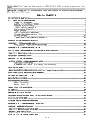
![∗56 ZONE PROGRAMMING MENU MODE
(press *56 while in Program mode)
Use ∗56 Zone Programming to program zones, zone types, report codes, enroll 5800 RF Wireless Transmitter serial
numbers, and identify the type of loop input device(s). This mode can also be used to enter alpha descriptors for programmed
zones; however, we recommend entering descriptors in menu mode ,82 (Alpha Descriptor Programming) after all zone
programming has been completed.
∗58 Expert Programming Mode offers a faster method of zone programming for those who have had previous experience in
programming control panels of this type.
SET TO CONFIRM? We recommend that you select “yes” to confirm the programming of every transmitter.
If selected, a prompt appears after entering the serial and loop numbers to confirm each transmitter)
0 = NO 1 = YES
Enter Zn Num. Enter the zone number being programmed:
01-06 = wired zones; 09-24 = wireless zones; 49-56 = button zones
(00 = Quit) 10 91 = addr. device report enable (Enter a report code for zone 91 to enable addressable device reporting.
92 = duress report enable (Enter a report code for zone 92 to enable duress reporting)
95, 96, 99 =emergency zones
00 to quit; [∗] to continue
Summary Screen for the selected zone is displayed.
Zn ZT P RC In: L “IN: L” = input type and loop; “HW: RT” = basic wired zone configuration (EOL, NO, NC) and response time
10 00 1 10 RF: 1 [∗] to continue
Each zone must be assigned to a zone type (list below), which defines the way in which the system
10 Zone Type responds to faults in that zone. Enter the desired zone type from the list below. If 00 is entered, Delete Zone
Perimeter 03 ? is displayed.
00 = Not used 07 = 24-Hr Audible 20 = Arm–STAY*
01 = Entry/exit #1 08 = 24-Hr Aux 21 = Arm–AWAY*
02 = Entry/exit #2 09 = Fire 22 = Disarm*
03 = Perimeter 10 = Interior w/Delay 23 = No Alarm Resp*
04 = Interior Follower 12 = Monitor Zone 24 = Silent Burglary
05 = Trouble Day/Alarm Night 14 = Carbon Monoxide 77 = Keyswitch
06 = 24-Hr Silent 16 = Fire w/Verify 81 = AAV Monitor Zone
*5800 button-type transmitters only 90 = Configurable
Enter the report code for this zone, which consists of 2 hexadecimal digits, each in turn consisting of two
10 Report Code numerical digits. For example, for a report code of “10,” enter 01 and 00.
1st 01 2nd 00 10 For Contact ID®, entering any non-zero entry as the first digit enables the report code for this zone.
1-9, 10 for 0, 11 for B, 12 for C, 13 for D, 14 for E, 15 for F
00 to disable;
[∗] to continue
This prompt appears only for zone numbers 01-06.
02 HARDWIRE TYPE Enter the desired hardwire type:
EOL 0 0 = EOL; 1 = NC; 2 = NO
[∗] to continue
This prompt appears only for hard-wired zones 01-06 (zone 02 is used as an example in display).
02 Response Time Enter the desired response time for this zone:
1 0 = 10mSec; 1 = 350mSec; 2 = 700mSec; 3 = 1.2 seconds
[∗] to continue
This prompt is skipped for zones 1-6.
10 INPUT TYPE All of the RF transmitters have one or more unique factory-assigned input loops (ID codes). Each of the
RF TRANS 3 input loops requires its own programming zone (e.g., a 5804's four button inputs require four programming
zones).Select the desired input type for the transmitter zone being programmed (some transmitters have
more than one input loop, each requiring its own zone; e.g., a 5804's four inputs requires four zones).
3 = RF (supervised RF transmitter; sends fault, restore, and low-battery signals, and sends periodic check-
in signals; transmitter must stay within receiver's range)
4 = UR (unsupervised RF transmitter; sends fault, restore, and low-battery signals, but does not send
periodic check-in signals; transmitter may be carried off-premises)
5 = BR (unsupervised button type RF transmitter; sends fault and low battery signals when activated, does
not send restore or check-in signals; transmitter may be carried off-premises)
[∗] to continue
NOTES:
• For basic wired zones, the Input Device type is automatically displayed as HW and cannot be edited.
For wireless transmitters, enroll the serial number and loop number.
10 INPUT S/N: L 1. a. Transmit two open/close sequences. If using a button-type transmitter, press and release the button
A022-4064 1 twice, but wait about 4 seconds before pressing the button the second time.
OR
b. Manually enter the 7-digit serial number printed on the label of the transmitter.
Press the [∗] key to move to the “L” position, then enter the loop number (see Loop Identification chart
on back cover).
If desired, you can press the [C] key to copy the previously enrolled serial number (used when
programming a transmitter with several input loops). The cursor moves to the loop number position.
c. To delete an existing serial number, enter 0 in the loop number field. The serial number will change to
0's. If 0 was entered in error, simply re-enter the loop number or press [#], and the serial number will
return to the display.
2. Press [∗] to continue. The system now checks for a duplicate serial/loop number combination.
– 12 –](https://image.slidesharecdn.com/honeywell-vista-10p-programming-guide-120917000741-phpapp01/85/Honeywell-vista-10p-programming-guide-12-320.jpg)
![If the serial/loop number combination is not a duplicate in the system, a display showing the serial number
10 INPUT S/N L and loop number entry appears.
A022-4064 1 [∗] to continue
This prompt will only appear if you answered “Yes” at the “SET TO CONFIRM” prompt.
XMIT TO CONFIRM The system now enters a confirmation mode so that the operation of the actual programmed input can be
PRESS , TO SKIP confirmed.
Activate the loop input or button that corresponds to this zone.
[∗] to continue
If the serial number transmitted does not match the serial number entered, a display similar to the one
Entd A022-4063 1 shown appears. If the loop number does not match, it will also be displayed.
Rcvd A022-4064 1 If so, activate the loop input or button on the transmitter once again. If a match is not obtained (i.e., summary
display does not appear), press the [#] key twice and then enter (or transmit) the correct serial number.
[∗] to continue
If the serial number transmitted matches the serial number entered, the keypad will beep 3 times
Zn ZT RC In: L and a summary display will appear, showing that zone's programming. Note that an “s” indicates
10 03 10 RF: 1s that a transmitter’s serial number has been enrolled.
[∗] to accept the zone information and continue
If you want to program descriptors for the zone now, enter 1 (yes) and refer to the *82 Descriptor
PROGRAM ALPHA? Programming section for procedures.
0 = NO 1 = YES 0 To program descriptors later, enter 0 (no).
[∗] to continue
If 0 (No) was entered at the Program Alpha prompt, the system will return you to the ZONE NUMBER
E N TE R Z N N U M. prompt. Repeat these steps for each zone in the system.
( 0 0 = Q U I T) 1 1 When all zones have been programmed, enter 00 as the zone number to quit.
[∗] to continue
Completing Zone Programming
When you have finished programming all zones, test each zone using the system’s TEST mode. Do not use the Transmitter
ID Sniffer Mode for checking wireless transmitting devices, as it will only check for transmission of one zone on a
particular transmitter, NOT the zones assigned to each additional loop.
NOTE: Following the successful enrollment of each wireless device, note the device serial number in the appropriate column
on the ENROLLED TRANSMITTERS worksheet in the Programming Form; then enter the other information (zone number,
zone type, loop number, etc.) relevant to that device.
∗58 EXPERT PROGRAMMING MODE
(press ∗58 while in Data Programming mode)
SET TO CONFIRM? We recommend that you select “yes” to confirm the programming of every transmitter.
If selected, a prompt appears after entering the serial and loop numbers to confirm each transmitter)
0 = NO 1 = YES
A summary screen will appear, showing zone 1’s currently programmed values.
Zn ZT RC HW: RT
Enter the zone number being programmed, then press [∗]. In this example, zone 10 is being entered
01 09 10 EL 1 (see Zone Number prompt in *56 Menu Mode for zone numbers).
[D] = for assigning wireless key programming templates (see Wireless Key Programming Templates section
Zn ZT RC IN: L below); lets you choose from a series of preset templates for easy programming of wireless key zones
00 = quit (when all zones have been programmed, press “00” to quit this menu mode)
10 00 10 RF – [∗] to continue
A summary screen with the selected zone’s current programming appears.
Zn ZT RC IN: L Begin programming zone information as follows:
10 00 10 RF 1 Enter Zone Type (ZT; see Zone Types listed in *56 Menu Mode “Zone Type” prompt), Report Code (RC; 0-9
only; use *56 mode to enter hex codes), and Input Device Type (IN)* sequentially (Loop Number (L) is
entered at the next prompt).
• Use the [A] (Advance) and [B] (Back) keys on the keypad to move the cursor within the screen.
• Use the [C] key to copy the previous zones attributes.
* If HW (hardwired) or AW (Auxiliary) is entered for Input Device Type, the display will be similar to the
prompt shown, except that HW or AW will be under “IN”.
Press [∗] to save the programming and continue. If needed, press the [#] key to back up without saving.
For wireless devices (input types RF, UR, BR), continue to the serial number/loop number prompt.
For wired devices, return to the initial summary screen prompt to begin programming the next zone.
Manually enter the serial number (found on the transmitter label), by typing digits in the “X” locations, using
10 INPUT S/N: L the [A] (advance) or [B] (back) keys as required.
A XXX- XXX – OR
Transmit two open/close sequences. If using a button-type transmitter, press and release the button twice,
but wait about 4 seconds before pressing the button the second time.
If you want to copy the previous zone’s serial number, press the [C] key.
Zn ZT P RC In L
Press [∗] to advance to the loop number, then enter loop number.
10 03 1 10 RF: 1s Press [∗] to accept the existing serial and loop number and continue to the “Confirm” prompt described in
*56 Menu mode above.
If necessary, press [#] to back up and re-enter or edit the serial number.
If the serial number transmitted matches the serial number entered, the keypad will beep 3 times and a
summary display will appear, showing the programmed information for that zone.
Press [∗] to begin programming the next zone. See first “Summary Screen” prompt paragraph.
– 13 –](https://image.slidesharecdn.com/honeywell-vista-10p-programming-guide-120917000741-phpapp01/85/Honeywell-vista-10p-programming-guide-13-320.jpg)
![WIRELESS KEY PROGRAMMING TEMPLATES
(press the [D] key from *58 Menu mode Summary Screen display)
This procedure programs the wireless keys, but a key is not active for arming/disarming until it is assigned to a user
number (see System Operation section, assigning attributes command in the Installation Instructions).
Enter desired template number 1–6 (see chart on previous page).
TEMPLATE ? Press [#] if you want to return to *58 Menu mode Summary Screen.
1–6 1 If necessary, press [#] to back up and re-enter template number.
Press [∗] to continue to template display.
The selected template is displayed.
L 01 02 03 04 Top line of display represents loop numbers, bottom line represents zone type assigned for each loop.
T 23 22 21 23 Press [∗] to accept template and continue.
The system will search for the highest available consecutive 4-zone group (the four zones in the case of the
ENTER START ZONE 5804 and 5804BD), and display the lowest zone number of the group.
00 = QUIT 36 If you want to start at a different zone, enter the zone desired, and press [∗]. If that zone number is
displayed, the system has the required number of consecutive zones available, beginning with the zone you
entered. If not, the system will again display a suggested zone that can be used.
If the required number of consecutive zones is not available at all, the system will display “00”.
Press [∗] to accept and continue.
Manually enter the serial number printed on the label for the wireless key or press and release the button to
INPUT S/N L transmit its serial number.
AXXX-XXXX – Press [∗] to accept the serial number. The system will check for duplicate.
If necessary, press the [#] key to back up without saving, and re-enter the serial number.
Use the [A] key to move forward within the screen, and the [B] key to move backward.
If “Yes” was entered at the SET TO CONFIRM? prompt (first prompt following entry into the ∗58 Expert
XMIT TO CONFIRM Programming Mode), this display appears.
PRESS , TO SKIP Confirm serial and loop numbers by activating the wireless key. Refer to the “Confirm” prompt described in
*56 Menu mode above for more information on confirming the serial number.
If the serial number transmitted matches the serial number entered, the keypad will beep 3 times and will
return you to the ENTER START ZONE NUMBER prompt to enter the starting zone for the next wireless key.
IMPORTANT: When confirmed, the key is not active for arming/disarming until it is assigned to a user
number (using the assigning attributes command, attribute “4”). See System Operation section in Installation
Instructions.
[∗] to skip confirm.
Wireless Key Predefined Default Templates
LOOP 3 GREEN/YELLOW
LED LOOP 2
YOU MUST OFF LOOP 2
PROGRAM ON
THIS BUTTON Note: RED/YELLOW
LOOP 4 LOOP 1 LOOP 4
These transmitters LED (YOU MUST
are not intended for PROGRAM
THIS BUTTON)
use in UL
LOOP 3
installations.
LOOP 1
••
••
• • ••
• • ••
•
•
ENROLL AS "BR"
•• ••
•
ENROLL AS "BR" 5804BD-007-V0
5804-001-V1
5804 Wireless Key Transmitter 5804BD 2-Way Wireless Key Transmitter
For 5804 Loop Function Zone Type For 5804BD Loop Function Zone Type
TEMPLATE 1 1 No Response 23 TEMPLATE 4 1 No Response 23
2 Disarm 22 2 No Response 23
3 Arm Away 21 3 Arm Away 21
4 No Response 23 4 Disarm 22
TEMPLATE 2 1 No Response 23 TEMPLATE 5 1 No Response 23
2 Disarm 22 2 Arm Stay 20
3 Arm Away 21 3 Arm Away 21
4 Arm Stay 20 4 Disarm 22
TEMPLATE 3 1 24-hour audible 7 TEMPLATE 6 1 24-hour audible 7
2 Disarm 22 2 Arm Stay 20
3 Arm Away 21 3 Arm Away 21
4 Arm Stay 20 4 Disarm 22
– 14 –](https://image.slidesharecdn.com/honeywell-vista-10p-programming-guide-120917000741-phpapp01/85/Honeywell-vista-10p-programming-guide-14-320.jpg)
![∗57 FUNCTION KEY PROGRAMMING MODE
(press ∗57 while in Data Programming mode)
The system provides the ability to program each of the four keypad function keys to perform one of 12 system operations. The
end user can then activate the function by simply pressing and holding the programmed key for 2 seconds. Typical functions
(listed below) include single-button arming, turning lights on/off, or single-button paging.
To assign emergency key functions (function key option “00”), first program the respective emergency zone number (95 for
“A” key, 96 for “C” key, 99 for “B” key) with the desired zone type using ∗56 (or ∗58) Zone Programming mode, then use ∗57
Function Key menu mode to assign the desired key.
To use a function key to activate a relay action (∗57 Menu mode key function 07), use ∗79 Menu mode to map the output, and
use ∗80 Menu mode to define the output’s action; select system operation type “66.”
To use a function key for a user macro, use ∗57 menu mode to activate the desired key, then define the actual macro
functions using the user code + [#] + [6] [6] command.
Press the desired function key, A-D. A 1 2 3
Press Key to Pgm
OFF AWAY STAY
NOTE: A key programmed as a function key is no longer
0 = Quit 0 available to be used as an end-user macro key or panic key. B 4 MAX 5 TEST 6 BYPASS
keypad_keys-00-001-V0
[∗] to continue
C 7 INSTANT 8 CODE 9 CHECK
D
* READY 0 #
Enter the desired function for this key:
Key "A" Func 00 = For the Function key selected, the functions are pre-defined as follows (system default):
Zone 95 00 If A selected = Zone 95 (emergency key, same as [1] [∗] pair)
If B selected = Zone 99 (emergency key, same as [∗] [#] pair)
If C selected = Zone 96 (emergency key, same as [3] [#] pair)
If D selected = Single-button paging
01 = Single-button paging (sends a 999-9999 message to pager)
02 = Display time
03 = Arm AWAY (reports as User 00 if closing reports are enabled)
04 = Arm STAY (reports as User 00 if closing reports are enabled)
05 = Arm NIGHT-STAY (reports as User 00 if closing reports enabled)
06 = Step Arming (arms STAY, then NIGHT-STAY if enabled by listing zones in Zone List 5, then
AWAY)
07 = Output Device Command (for device programmed as system operation type 66 in *80 Menu Mode)
08 = Communication Test (sends Contact ID code 601)
09= Macro Key (defined by [#] [6] [6] command)
[∗] to continue; returns to key number prompt with the next function key letter displayed.
OUTPUT DEVICE PROGRAMMING OVERVIEW (*79/*80 MENU MODE)
Output Devices: The system supports up to 4 relays plus 2 built-in trigger outputs. These “output devices” are
assigned to system-wide output numbers (01-04, 17, 18). Relays are identified by the relay
module’s device address and the relay position on the module (i.e. the physical relay number, 1-4,
on the module). Built-in triggers are identified by the output number, 17 for Trigger 1 and/or 18 for
Trigger 2.Use *79 Menu Mode to assign output numbers and map them to device addresses.
To program a device for manual activation (user code + [#] [7] / [#] [8] + 2-digit device number) or
for scheduled automatic activation, simply map the device using *79 Menu mode.
To program a device to automatically activate upon a system event (or function key), use *79 Menu
mode to map the device, then use *80 Menu mode to define the automated device action.
NOTE: You must map output devices using *79 Menu Mode before you can use *80 menu Mode.
Output Functions: The system also provides up to 12 installer-defined output functions, which can be assigned to any of
the physical outputs. Therefore, the action of any one of the outputs can be based on as many of
these functions as desired. This lets a single relay perform many functions. Use *80 Menu Mode to
define output functions, which control the output devices. If the device action is based on more than
one zone, use *81 Zone List menu mode to assign the zones.
IMPORTANT: Relays are not recommended for life safety applications.
MENU NAVIGATION NOTE: For *79 and *80 menus, press the [,] key to accept an entry and advance to the next prompt.
Use the [#] key to go back to the last question if needed (to check or change an entry). Press [,] to go forward again.
– 15 –](https://image.slidesharecdn.com/honeywell-vista-10p-programming-guide-120917000741-phpapp01/85/Honeywell-vista-10p-programming-guide-15-320.jpg)
![∗79 OUTPUT DEVICE MAPPING
(press *79 while in Data Programming Mode)
Use this menu to assign the Relay Module device address and specific relay numbers. The system is based on predefined
module addresses. The address for the 4204 is 12. Refer to the “Module Address” prompt and set the module’s address (via
module DIP switches) accordingly.
Enter the logical (or reference) relay number as used in the system.
ENTER OUTPUT NO.
01-04 = relays; 17-18 = on-board triggers (can be programmed for inverted output; see next prompt)
00 = QUIT xx
[∗] to continue
This prompt appears only for triggers 17 and 18.
17 OUT NORM LOW
0 = no (standard default); sets the trigger output level normally high
0 = NO 1 = YES 0 1 = yes; sets the trigger output normally low (can be used for resetting 4-wire smoke detectors by
connecting trigger wire to the negative power terminal of the smoke detector, selecting 1 at this prompt,
and setting as zone type 54, fire zone reset, in *80 Menu mode)
[∗] to return to Output Number prompt
Enable or delete this output.
XX OUTPUT TYPE
0 = delete this output number; 1 = enable output
DELETE? 0
[∗] to continue
Enter the module’s predefined address “12” (set the module’s DIP switches to “12”).
XX MODULE ADDR
[∗] to continue
07-15 yy
Enter the actual (or physical) relay number, 1-4, with respect to the Relay Module upon which it is located.
XX REL POSITION
[∗] to return to the Output Number prompt for programming the next device
1-4 zz
*80 OUTPUT DEFINITION MODE
(press ∗80 while in Data Programming mode)
Use this mode to program output function definitions (up to 12 functions) that provide automated control of any of the output
devices, based on events occurring on individual zones or zones with certain zone types. Each output definition is identified
by an output function number, and includes the following components:
Output Definition Components
Component Description
Output Function No. A reference number that defines an output’s characteristics.
Activated By Determines whether the initiating event occurs on a zone, a zone list, or a zone type.
Event Event that triggers the output action. Can be an event occurring on a specific zone number or a zone
list, or a specific zone type.
Output Action Defines the action of the relay when the defined event occurs. Can close for 2 seconds, stay closed
until reset, continuously pulse (1-second close-open-close-open, etc.), toggle the device state, or
activate for a defined duration (set in data field *177).
Output No. Assigns this function to a specific output number (defined in *79 Menu Mode). This is the output
number that will perform this function upon the triggering event. Note that each defined function is
associated with only one output number. This means that if more than one output device needs to
perform this particular function, you need to define another output function number with the same
attributes, but assign the appropriate output number. (i.e. output devices can be assigned more than
one function number, but each function number can only be assigned a single output number.
Enter the output function number to be defined
Output Funct. # 01-12 = output function number
(00 = Quit) 01 [∗] to continue; 00 = exit
This screen displays a summary of the current output programming
01 A E Trig A = Output Action; E = Triggering event; Trig = Trigger type
?00 0 0 – ZL=00 Question mark indicates the device shown has not been mapped. Use *79 Menu mode to map the device.
[∗] to continue
Select where the initiating event for this output definition is to occur.
01 Activated By: 0 = delete (deletes the output function and any previous programming)
Zone List Delete? To delete this output definition, press 1.
0 = NO, 1 = YES If you do not want to delete this output,. press 0.
1 = zone list (go to “A” prompt); 2 = zone type (go to “B” prompt); 3 = zone number (go to “C” prompt)
[∗] to continue
– 16 –](https://image.slidesharecdn.com/honeywell-vista-10p-programming-guide-120917000741-phpapp01/85/Honeywell-vista-10p-programming-guide-16-320.jpg)
![“A”
If zone list was selected, this screen appears. Otherwise skip to the next prompt.
01 Zn List Enter the desired zone list number associated with this output number:
1 01-08 = zone list (Do not use pager zone list 09 in output definitions)
Enter the zone list event that will activate this output:
Enter Event 0 = restore; 1 = alarm;
Alarm 1 2 = fault; 3= trouble
NOTE: For alarm, fault, and trouble, an event on ANY zone in the list activates the output, but ALL zones in
the list must be restored before the output is restored.
Press [∗] to continue and skip to the “Output Action” prompt.
“B”
If zone type was selected, this screen appears. Otherwise skip to the next prompt.
01 Enter Zn type Enter the desired zone type for this output number.
Perimeter 03 CHOICES FOR ZONE TYPES:
00 = Not Used 05 = Trouble Day/Alarm Night 12 = Monitor Zone
01 = Ent/Exit #1 06 = 24 Hr Silent 14 = Carbon Monoxide
02 = Ent/Exit #2 07 = 24 Hr Audible 16 = Fire w/verification
03 = Perimeter 08 = 24 Hr Aux 23 = No Alarm Response
04 = Interior Follower 09 = Fire 24 = Silent Burglary
10 = Interior w/Delay 77 = Keyswitch Zone
81 = AAV Monitor Zone
90 = Configurable
CHOICES FOR SYSTEM OPERATION:
20 = Arming–Stay 36 = At Bell Timeout*** 52 = Kissoff
21 = Arming–Away 38 = Chime 54 = Fire Zone Reset
22 = Disarming 39 = Any Fire Alarm 58 = Duress
31 = End of Exit Time 40 = Bypassing 60 = AAV
32 = Start of Entry Time 41 = AC Power Failure 66 = Function Key†
33 = Any Burglary Alarm 42 = System Battery Low 67 = Bell Fail
43 = Comm. Failure 68 = Telco line cut
78 = Keyswitch Red LED
79 = Keyswitch Green LED
*** Or at Disarming, whichever occurs earlier.
† Use *57 Menu Mode to assign the function key (function “07”).
Note: In normal operation mode:
Code + # + 7 + NN Key Entry starts Device NN.
Code + # + 8 + NN Key Entry stops Device NN.
Press [∗] to continue and skip to the “Output Action” prompt.
“C”
If zone number was selected, this screen appears.
01 Enter Zn No. Enter the desired zone number associated with this output number.
12 Press [∗] to continue.
Enter the zone event that will activate this output.
01 Enter Event 0 = restore; 1 = alarm/fault/trouble
Restore 0
Press [∗] to continue to the “Output Action” prompt
Enter the desired device action as listed below.
01 Output Action 0 = off 4 = Change Device State
Close for 2 sec 1 1 = Close for 2 seconds 5 = Duration 1 (see data field *177)
2 = Stay Closed 6 = Duration 2 (see data field *177)
3 = Pulse 1 sec ON, 1 sec OFF
Press [∗] to continue.
Enter the device output number (programmed in *79 Menu Mode) you want associated with this output.
Enter Output No. 01-04 = output no.
R02 02 17-18 = on-board triggers
Press [∗] to continue.
A summary screen appears showing the programmed settings.
02 A E P TRIG
Press [∗] to return to output function number prompt.
R02 1 1 3 ZL=1
– 17 –](https://image.slidesharecdn.com/honeywell-vista-10p-programming-guide-120917000741-phpapp01/85/Honeywell-vista-10p-programming-guide-17-320.jpg)
![∗81 ZONE LIST PROGRAM MODE
(press ∗81 while in Data Programming mode)
Zone lists let you group individual zones for use with certain system actions. The following table shows the available zone lists
and their purposes:
List No. Used for…
1, 2 general purpose
3 chime-by-zone
4 cross zones
5 night stay zones
6 general purpose
VISTA-10PSIA: dial delay disable
7 general purpose
VISTA-10PSIA: unlimited reports
8 general purpose
9 zones that activate Pager 1
Enter the Zone List Number to program (or 00 to end these entries).
Zone List No. 01-09 = zone list number
(00 = Quit) 01 [∗] to continue
Enter each zone number followed by [∗] to add each zone to the zone list.
01 Enter Zn Num. 01-06 = wired zones; 09-24 = wireless zones; 49-56 = button zones
(00 = Quit) 00 91 = addr. device report enable (Enter a report code for zone 91 to enable addressable device reporting.
92 = duress report enable (Enter a report code for zone 92 to enable duress reporting)
95, 96, 99 =emergency zones
00 to continue
IMPORTANT: Do not include fire zones in zone lists that are used to STOP device actions.
0 = don’t delete list; current zone list remains saved
01 Del Zn List? 1 = delete this zone list; All zones in the zone list will be deleted automatically and the system returns to the
0 = No 1 = Yes 0 Zone List No. prompt.
[∗] to continue
0 = don’t delete zones; save zone list and return to the Zone List No. prompt.
01 Delete Zone? 1 = go to next prompt to delete zones
0 = No 1 = Yes 0 [∗] to continue
Enter each zone to be deleted from the list
01 Zn to Delete? 01-64 = zones to be deleted from list followed by [∗] to accept each zone
(00 = Quit) 00 00 when done to return to the Zone List No. prompt
NOTES:
• Any list may include any or all of the system's zone numbers.
• A zone list can be assigned to more than one output relay.
• When creating zone list 4 for cross zoning, include only zones assigned to zone types 3, 4, or 5. Do not include zones that
have delays (entry/exit zones, interior w/delay) or 24-hour zones, as these zone types may produce unpredictable operation
and may not function as intended. See field *85 for Cross Zone Timer option.
• Zone List 6: VISTA-10PSIA: See field *50 for Dial Delay Disable option.
• Zone List 7: VISTA-10PSIA: See field *93 for Unlimited Reports option.
*82 ZONE DESCRIPTOR PROGRAMMING MODE
(press *82 while in Data Programming mode)
The system lets you assign zone descriptors for protection zones, keypad panics, and RF receiver supervision faults. Each
description can be composed of a combination of words (up to 3) selected from a vocabulary of 196 words stored in memory
(see a following page). In addition, up to 10 installer-defined words can be added to those already in memory. Thus, when an
alarm or trouble occurs in a zone, an appropriate description for that zone's location can be displayed at the keypad. Zone
descriptors are recommended for systems using Alpha display keypads, and are necessary if a Phone Module is used.
NOTE: You can enter zone descriptors when the zone is being defined in ,56 Menu mode, but we recommend you do it
using ,82 Menu mode.
If using a 4286VIP Phone Module, select from those words in the Alpha Vocabulary List shown in boldface
type. The phone module will not provide annunciation of the other words.
If a 4286 Phone Module is added to an existing system, the Alpha descriptors presently in the system
should be reprogrammed, selecting from those words shown in boldface type in the Alpha Vocabulary List.
The phone module will not provide annunciation of any other words.
When defining descriptors:
• Pressing the [6] key accepts the entered index number and moves the cursor to the next position.
• Pressing the [8] key saves the entered descriptor and moves to the next descriptor.
– 18 –](https://image.slidesharecdn.com/honeywell-vista-10p-programming-guide-120917000741-phpapp01/85/Honeywell-vista-10p-programming-guide-18-320.jpg)
![Press 1 to program descriptors.
Program Alpha ? 0 = exit this mode
0 = N o , 1 = Ye s 0
To program standard alpha descriptors from the fixed vocabulary, press 0. The system will then
Custom W ords ? automatically display the descriptor for zone 1.
0 = N o , 1 = Ye s 0 0 To define custom words (described below in “Adding Custom Words” section), press 1.
Summary screen of zone 1 descriptor (if programmed) is displayed.
, ZN 01
Press [∗] to start blinking cursor at zone number, then enter the zone number for which the descriptor is
being programmed.
• If a descriptor is programmed for that zone, it is displayed.
• To delete or change a previously programmed descriptor, press the same zone number. This will clear that
descriptor and move the cursor to the first word position.
• If you do not wish to change the existing descriptor, enter the next zone number for which you wish to
enter (or check) a descriptor. A summary display for that zone will appear. You must then enter the same
zone number again to program a descriptor for that zone.
• If no descriptor has been programmed for that zone, the cursor moves to first word position.
Select first word of descriptor:
, ZN 01 Press [#] plus the 3-digit index number for the first word from the Alpha Vocabulary List. See index for entries.
Example: The descriptor that we wish to enter for zone 1 is BACK DOOR. From the list, BACK = 013.
Therefore, you would enter #013.
NOTE: If you enter the wrong word, simply press [#] plus the correct 3-digit number for the word you want.
Save first word of descriptor:
, ZN 01 BACK 6 = save word and go to next word in this descriptor
8 = save word and end descriptor if this is the only word used for the descriptor - go to summary screen
, ZN 01 BACK Enter the 3-digit number for the next word. In the example, the word is DOOR, whose number is “057.”
See index for entries.
D OOR [∗] to continue
Save second word of descriptor:
, ZN 01 BACK 6 = save word and go to next word in this descriptor
8 = save word and end descriptor if this is the only word of the descriptor - go to summary screen
DOOR
The two words in the example have now been entered. Note, however, that up to three words may be
entered (provided the number of characters will fit on the screen).
Summary Screen
, ZN 01 BACK The blinking cursor will disappear, indicating that the word(s) are stored in memory for that zone.
DOOR To enter a descriptor for the next zone, press [∗] plus the desired zone number (e.g., ∗02).
The summary display for that zone will appear.
Repeat the previous steps to enter the descriptor for the next zone.
To exit the Alpha descriptor mode, enter zone “00” at the summary display, which returns you to the
Program Alpha prompt. Enter “0” at that prompt to exit.
ADDING CUSTOM WORDS
(will not be annunciated by 4286 Phone Module)
The “Program Alpha ?” prompt will appear.
Program Alpha ? 1 = program zone descriptors, custom message, or reminder words
0 = N o , 1 = Ye s 0 [∗] to continue; 0 = exit
Custom words let you assign custom zone descriptors, a custom message (which replaces the “DISARMED
Custom W ords ? READY TO ARM” message), and “reminder” words (for Scheduling mode, event “10”).
0 = N o , 1 = Ye s 0 NOTE: Do not assign reminder words if using fixed-word keypads.
1 = yes, program custom words or reminder words; 0 = no, go to zone descriptors (see above)
If “1” selected, enter the 2-digit custom word number (01-10, or 11 for custom message) to be programmed,
corresponding to index numbers 245 - 254 respectively (for example, if you are creating the first custom
word or word-string, enter 01, for the second, enter 02, etc.). A cursor appears at the beginning of the
second line.
Custom? 00 01-07 = custom words; 08-10 = “reminder” words used with scheduling mode
11 = custom message (replaces “DISARMED READY TO ARM” message)
Custom? 01 A cursor appears at the beginning of the second line.
Special Keys: [6] = accept character and move cursor to next position to right
[4] = move cursor to left
[8] = save custom word
1. Refer to the Character Chart on the next page.
Press [#], followed by the two-digit entry for the first letter you want to display (e.g., # 6 5 for “A”).
Press [6] to accept the character and move the cursor to the right, in position for the next character.
2. Repeat Step 1 to enter the next characters until the desired custom word is entered. You can use the
[4] key to move the cursor to the left, if necessary.
Each custom word can be a maximum of 10 characters.
3. When done, press the [8] key to save the custom word and return to the “Custom ?” prompt.
4. Repeat steps 1-3 to enter other custom words. To change a custom word, simply overwrite it.
To exit, enter “00,” which returns you to the Program Alpha prompt. Enter “0” at that prompt to exit.
– 19 –](https://image.slidesharecdn.com/honeywell-vista-10p-programming-guide-120917000741-phpapp01/85/Honeywell-vista-10p-programming-guide-19-320.jpg)

![SCHEDULING MODE
Start Scheduling mode by entering installer code + [#] + [6] [4] while in normal operating mode.
The system provides 2 schedules (one for the installer, one for the end user), which can be used to control 11 types of system
events at pre-defined times.
NOTES: • The master code can only access schedule 01 and events 00-07.
• System clock must be set before schedules can take effect.
• Programmed schedules do not take effect until the next scheduled “start” time. (e.g., if programming a schedule
time window for 8AM to 5PM, the schedule does not take effect until 8AM after the schedule has been
programmed.)
Enter the desired schedule number.
ENTER SCHED NO. 01 = end-user schedule; 02 = installer-only schedule; 00 = exit scheduling mode
00=QUIT 00 [∗] to continue
Enter the desired event number for event you want to occur at a specified time.
ENTER EVENT Events 10-11 are reserved for the installer only.
CLEAR EVENT 00 00 = clear event
01 = Relay On/Off
02 = User Access
NOTE: Events 07 and 10 03 = Latch Key Report to Pager (sent to all pagers; message sent is 777-7777; user must be enabled for
cause the keypad to paging and system must be armed before reporting can occur.)
beep every 30 seconds 04 = Forced Stay Arming (forced bypass is automatically enabled regardless of setting in field *23)
when messages are 05 = Forced Away Arming (forced bypass is automatically enabled regardless of setting in field *23)
displayed. Stop the 06 = Auto Disarm
beeps by pressing any 07 = Display “Reminder”
key. 10 = Display custom words (system displays custom words 8, 9, and 10 at defined time; can be used as
installer’s reminder message to the end user)
11 = Periodic Test Report
[∗] to continue
This prompt appears if event “1” (relay on/off) was selected, otherwise it is skipped.
DEVICE NUMBER
Enter the physical device number as programmed in ∗79 Menu Mode.
XX 01-04 = device number; 17, 18 = built-in triggers 1 and 2 respectively
[∗] to continue to the “Start” prompt
This prompt appears if event “2” (user access) was selected. Otherwise it is skipped.
GROUP NUMBER 1-8 = group number
X [∗] to continue to the “Start” prompt
Enter the event’s start time and days of the week to occur.
START SMTW TFS 01-12 = hour; 00-59 = minute; 0 = AM; 1 = PM
HH MMAM 0 0 1 0 0 0 0 Days = position the cursor under the desired days using the [∗] key to move forward, then press “1” to select
the desired day(s)
[∗] to continue
Enter the event’s stop time and days of the week to occur.
STOP SMTW TFS This entry applies only to the following events: 1 (relay on/off); 2 (user access); 3 (latch key report)
HH MMAM 0 0 1 0 0 0 0 01-12 = hour; 00-59 = minute; 0 = AM; 1 = PM
Days = position the cursor under the desired days using the [∗] key to move forward, then press “1” to select
the desired day(s)
[∗] to continue
Enter the desired repeat option for this schedule.
REPEAT OPTION e.g., To make a schedule that happens everyday you would select all days with a repeat count of 1. To
0-4 X make a schedule that runs for one week then stops, select everyday with a repeat count of 0.
0 = do not repeat; 1 = repeat schedule weekly; 2 = repeat schedule biweekly (every other week)
3 = repeat every 3rd week; 4 = repeat every 4th week (28 days)
[∗] to continue
Select whether you want this schedule to start and stop at random times.
RANDOMIZE If selected, the scheduled start and stop times will vary within 60 minutes of the “hour” time. For example, if
0=NO 1=YES X a schedule is set to start at 6:15pm, it will do so the first time 6:15pm arrives, but on subsequent days it will
start anytime between 6:00 and 6:59 p.m.
[∗] to continue
NOTE: Do not use the random option if the start and stop times are within the same “hour” setting, otherwise
unpredictable results may occur (e.g., the randomized stop time may occur before the start time).
– 21 –](https://image.slidesharecdn.com/honeywell-vista-10p-programming-guide-120917000741-phpapp01/85/Honeywell-vista-10p-programming-guide-21-320.jpg)
![∗29 COMMUNICATION DEVICE MENU MODE (Pass-Through Programming)
This mode is for programming an IP, GSM, or IP/GSM Communicator Module using an alpha keypad. Alternatively, these
options can be programmed via the AlarmNet Direct website. After programming is complete, the module must be registered
with AlarmNet before reporting via the communication device can occur. Refer to the device’s instructions for registration
procedures.
NOTE: The module must be set to device address 3.
IMPORTANT: The use of an IP/GSM Communicator Module
requires an AlarmNet–I account. Please obtain the account
information from the central station prior to programming this
module.
Using an Alpha Keypad as a 7720P Programming Tool
When programming with ∗29 menu mode, the alpha
keypad mimics the functions of the 7720P Programming A B C
Tool. See figure to right and table below for 7720P key
ARMED (A) BS/ESC 1 OFF 2 AWAY 3 STAY
D E F
functions. Each key has two possible functions: a normal READY (B) / 4 MAX 5 TEST 6 BYPASS
function and a SHIFT function. S T X
Normal functions: The numeric values labeled directly SHIFT
(C) N/Y 7 INSTANT 8 CODE 9 CHIME
on the keys and the left-hand functions shown in FUNCTION SPACE ENTER
diagram on the ABC keys. To perform a normal key
WHEN LIT (D) SHIFT READY 0 #
function, simply press the desired key.
SHIFT functions: Those functions shown in diagram 6160-7720P-001-V0
above the numerical keys and the right-hand functions
shown on the ABC keys. To perform a SHIFT key 7720P Emulation Template for Alpha Keypads
function, press SHIFT key (D key), then press the
desired function key (shift function is indicated by the lit
READY LED).
∗29 IP/GSM Program Mode
Press ∗29 while in Data Field Programming mode. The following prompts appear.
Enable IP/GSM? If using a communication device, enter 1 at this prompt and enter 1-Prog
ENABLE IP/GSM? at the next prompt to program and register the device. Use the
0 = no, not using IP or GSM;
0=No, 1=Yes 1 = yes using IP and/or GSM Installation Guide included with the communication device for details of
module the device’s programming prompts and instructions for registration.
[∗] to continue
[Default = 0 (no IP and/or GSM)]
Programming / Select whether you want to program the communication device or enter
1=PROG 2=DIAG the device’s diagnostic mode.
Diagnostics Select
0=QUIT 1= Prog (program the IP/GSM
options) Diagnostic Mode Note: Diagnostic mode option available only for
2 = Diag (enter diagnostic communicators with firmware version 2.4.16 or higher.
mode)
0 = Quit; returns to data field
programming mode
Normal and SHIFT key Functions While in ∗29 Menu Mode
Key Normal Key Function SHIFT Key Function
(A) = BS/ESC [BS]: Press to delete entry [ESC]: Press to quit Program Mode
Also, can reset EEPROM defaults †
(B) = ↓/↑ [↓]: Scroll down programming [↑]: Scroll up programming
(C) = N/Y [N]: Press for "NO" answer [Y]: Press SHIFT-Y for "YES" answer
(D) = SHIFT Press before pressing a SHIFT key function. Will light READY LED. LED goes out once a
key is pressed. Press again for each SHIFT function desired.
1/A [1]: For entering the number 1 [A]: Used for entering C.S. ID number
2/B [2]: For entering the number 2 [B]: Used for entering C.S. ID number
3/C [3]: For entering the number 3 [C]: Used for entering C.S. ID number
4/D [4]: For entering the number 4 [D]: Used for entering C.S. ID number
5/E [5]: For entering the number 5 [E]: Used for entering C.S. ID number
6/F [6]: For entering the number 6 [F]: Used for entering C.S. ID number
7/S [7]: For entering the number 7 [S]: Press to display diagnostic status
8/T [8]: For entering the number 8 [T]: Press to send TEST messages
9/X [9]: For entering the number 9 [X]: Press to reset the IP/GSM
[∗] / SPACE [∗]: Used to select programming options [SPACE]: Not used
0 [0]: For entering the number 0
[#] / ENTER [#] / ENTER: Press to accept entries No SHIFT function
† Active only when the "REVIEW?" prompt is displayed
– 22 –](https://image.slidesharecdn.com/honeywell-vista-10p-programming-guide-120917000741-phpapp01/85/Honeywell-vista-10p-programming-guide-22-320.jpg)
![UPLOADING/DOWNLOADING VIA THE INTERNET
UL: Up/downloading via the Internet has not been evaluated by UL.
This control, when used with a compatible Internet/Intranet Communication Device, supports upload/download programming
capability via the Internet using the AlarmNet network or, depending on the communication module used, a Private local area
network (Intranet). This allows site maintenance independent of central station monitoring, and modification to sites globally
via the Internet. Depending on the module used, Internet connection from the protected premises is either via high speed
(broadband) cable or phone service, or via the GSM/GPRS digital cellular network (GSM modules).
Refer to the instructions provided with the communication module for information regarding its installation, programming, and
registration. The System Requirements table below lists two sets of system requirements, depending upon whether you
intend to communicate over the Internet or whether you are communicating over a Private LAN (Intranet).
Compatible Communication Modules: The following modules support Internet uploading/downloading, but future modules
may also provide Internet upload/download support; refer to the module’s instructions for compatibility. Compatible Modules:
7845i-ent, 7845i-GSM, 7845GSM
System Requirements
Internet Communication Intranet (Private LAN) Communication, if applicable*
At the Installation Site: At the Installation Site:
• Appropriate Internet Communication Module • Internet/Intranet Communication Module
• 7720P Programmer • 7720P Programmer
• Broadband Internet Access (for wired modules) • Ethernet Network Connection
• Broadband (Cable/DSL) Modem (for wired modules) • IP compatible Control Panel
• Broadband (Cable/DSL) Router (for wired modules if At the Downloading Office:
connecting more than one device to the Internet)
• 7810iR-ent IP Receiver
• IP compatible Control Panel
• Internal Router
At the Downloading Office: • Computer(s) running the following software:
• Broadband Internet Access - Compass Downloading Software version that supports IP
• Broadband (Cable/DSL) Modem upload/download for this control.
• Broadband (Cable/DSL) Router (optional, if connecting - Compass Connect Data Server Application
more than one device to the Internet) - Compass Connect Control Server Application
• Computer running Compass Downloading Software * see module’s instructions for applicability for LAN usage
version that supports Internet upload/download for this (ex. 7845i-ent supports LAN)
control. NOTE: Compass, the Compass Connect Data Server, and the
Compass Connect Control Server applications may all be installed
on the same computer if desired. If they are installed on one
computer, the computer must have a fixed IP Address.
To set up the control panel, do the following:
1. Connect the module to the control panel’s ECP (keypad) terminals.
2. Internet Users: For wired modules, connect the module to the Internet via a cable/DSL modem and router.
Intranet Users: Connect the module to the Intranet (LAN) via the appropriate Ethernet connection.
3. Enable the module as a Long Range Radio in the control panel (programming field *29) to enable alarm reporting and
module supervision.
4. Set the module for address 3.
5. Program the module as required using the module’s programming methods (ex. 7720P programmer).
6. Register the module with AlarmNet. The module must be registered before downloading or alarm reporting can take place.
To perform upload/download functions:
1. Connect the computer to the Internet and start the Compass downloading software.
2. Open the control’s account, then select the Communications function and click the Connect button.
3. At the Connect screen, check that the control’s MAC address is entered and the TCP/IP checkbox is checked.
4. Click Connect. The Internet connection to the control is made automatically via AlarmNet.
5. Once connected, use the Compass downloading software as normal to perform upload/download functions.
SETTING THE REAL-TIME CLOCK
IMPORTANT: The Real-Time Clock must be set before the end of the installation.
NOTE: System must be disarmed before the date/time can be set.
1. Master Code + [#] + [6] [3]
2. Press [∗] when the time/date is displayed.
A cursor appears under the first digit of the hour.
To move cursor ahead, press [∗]. To go back, press [#].
• Enter the 2-digit hour setting.
• Enter the 2-digit minute setting.
• Press [1] for PM or [2] for AM.
• Enter the last two digits of the current year.
• Enter the 2-digit month setting.
• Enter the 2-digit day setting.
3. To exit, press [∗] when cursor is at the last digit, or wait 30 seconds.
– 23 –](https://image.slidesharecdn.com/honeywell-vista-10p-programming-guide-120917000741-phpapp01/85/Honeywell-vista-10p-programming-guide-23-320.jpg)
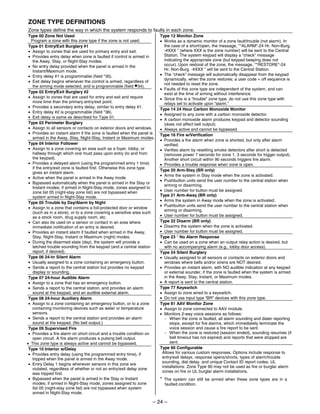


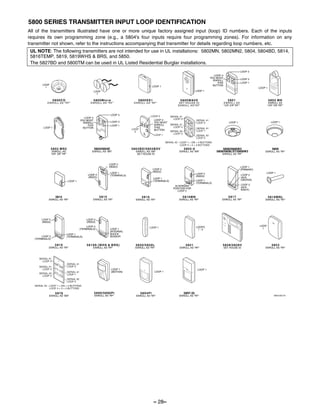
![SCHEDULE WORKSHEET
(installer code + [#] + [6] [4]; master code can only access schedule 01 and events 00-07)
No. Event Device No. Group No. Start Time/ Stop Time/ Repeat Random
(see list below) for “01” events: for “02” events: Days Days (1-4) (yes/no)
enter 01-04 enter 1-8
01 (user)
02 (installer)
Events: Master/Installer Installer Only
00 = clear event 04 = forced STAY arm 10 = display custom words 8-10
01 = device on/off 05 = forced AWAY arm 11 = periodic test report
02 = user access 06 = auto disarm
03 = latch key report 07 = display “reminder”
Repeat Options: 0 = none; 1 = repeat weekly; 2 = repeat every other week; 3 = repeat every third week; 4 = repeat every fourth week
*56 ZONE PROGRAMMING WORKSHEET
[default shown in brackets]
Zone Zn Type Report Hardwire Rsp. Time Location
Type
1 [01] [EOL] [1]
2 [01] [EOL] [1]
3 [03] [EOL] [1]
NOTES: 4 [03] [EOL] [1]
Zone Type: see chart on
page 7; 5 [03] [EOL] [1]
6 [03] [EOL] [1]
Hardwire Type (zns 1-6):
0 = EOL Zone Zn Type Report Input Type Loop Serial No. Location
1 = NC 9
2 = NO
Input Type: 10
3 = RF (zones 9-24)
4 = UR (zones 9-24) 11
5 = BR (zones 49-56)
12
Response Time: 13
0 = 10msec
1 = 350msec 14
2 = 700msec
3 = 1.2 sec
15
16
Reserved Zones
17
91 = addressable device
report enable/disable 18
default zone type =
[05]. 19
92 = Duress report 20
enable/disable
21
22
23
24
49 [BR]
50 [BR]
51 [BR]
52 [BR]
53 [BR]
54 [BR]
55 [BR]
56 [BR]
95 [00] N/A N/A N/A keypad [1] / [∗]
96 [00] N/A N/A N/A keypad [3] / [#]
99 [06] N/A N/A N/A keypad [∗] / [#]
– 29–](https://image.slidesharecdn.com/honeywell-vista-10p-programming-guide-120917000741-phpapp01/85/Honeywell-vista-10p-programming-guide-29-320.jpg)
![∗57 FUNCTION KEY PROGRAMMING WORKSHEET
Option Function A B C D Comments
01 Paging
02 Time Display
03 Arm AWAY
04 Arm STAY
05 Arm NIGHT-STAY
06 Step Arming
07 Device Activation Device:
08 Comm. Test
09 Macro Key
00 Emergency Keys: zone 95 zone 99 zone 96 paging
Personal Emergency n/a
Silent Alarm n/a
Audible Alarm n/a
Fire n/a
Emergency Keys: A = paired keys [1] / [∗] (zone 95); B = paired keys [∗] / [#] (zone 99); C = paired keys [3] / [#] (zone 96)
∗79 RELAY MAPPING WORKSHEET
(Must program before using *80)
Output No. Module Addr. Pos (1-4) Description
01 12
02 12
03 12
04 12
17 On-Board Trigger 1: Norm output =
18 On-Board Trigger 2: Norm output =
∗80 OUTPUT DEFINITIONS WORKSHEET
Output Activation Type and Detail Event (for zone list/activated by) Action Output Device
Function Activated by Zone List Zone Type Zone No. By Zone List By Zone No. 0 = off Number Type
Number 0=delete (ZL) (ZT) (ZN) 1 = close 2 secs 1-4
1-12 1=zn list 1-8 = list (see table 00=none 0 = restore 0 = restore 2 = stay closed 17, 18 R = relay
2=zn type below) 01-06, 1 = alarm 1 = alrm/flt/trbl 3 = pulse T = trigger
3=zn no. 09-24 2 = fault 4 = toggle
49-56 3 = trouble 5 = duration 1††
6 = duration 2††
1
2
3
4
5
6
7
8
9
10
11
12
ZONE TYPE/SYSTEM OPERATION – Choices for Zone Types are:
00 = Not Used 05 = Trouble Day/Alarm Night 10 = Interior w/Delay 24 = Silent Burglary
01 = Entry/Exit#1 06 = 24 Hr Silent 12 = Monitor Zone 77 = Keyswitch
02 = Entry/Exit#2 07 = 24 Hr Audible 14 = Carbon Monoxide 81 = AAV Monitor Zone
03 = Perimeter 08 = 24 Hr Aux 16 = Fire w/Verification 90 = Configurable
04 = Interior Follower 09 = Fire 23 = No Alarm Response
Choices for System Operation are: Note: In normal operation mode:
20 = Arming–Stay 38 = Chime 52 = Kissoff
21 = Arming–Away 39 = Any Fire Alarm 54 = Fire Zone Reset Code + # + 7 + NN Key Entry starts Device
22 = Disarming (Code + OFF) 40 = Bypassing 58 = Duress Code + # + 8 + NN Key Entry stops Device
31 = End of Exit Time 41 = AC Power Failure 60 = AAV Trigger
32 = Start of Entry Time 42 = System Battery Low 66 = Function key†
33 = Any Burglary Alarm 43 = Communication Failure 67 = Bell Failure *** Or at Disarming, whichever occurs earlier.
36 = **At Bell Timeout*** 68 = Telco Line Fault † Use *57 Menu mode to assign the function key.
78 = Keyswitch Red LED††† †† Duration is set in program field *177.
79 = Keyswitch Green LED††† ††† Device action not used for these choices.
– 30–](https://image.slidesharecdn.com/honeywell-vista-10p-programming-guide-120917000741-phpapp01/85/Honeywell-vista-10p-programming-guide-30-320.jpg)
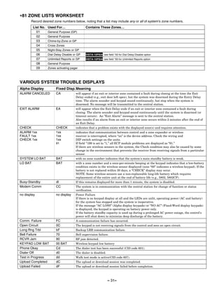


This document is the programming guide for the ADEMCO VISTA-10P and VISTA-10PSIA security systems. It provides an overview of the various programming modes used to program the system, including data field programming, zone programming, output programming, and scheduling. Instructions are given for entering programming mode, navigating between data fields, and programming system options.


![Mic1462 quick start_[1738]](https://cdn.slidesharecdn.com/ss_thumbnails/mic1462quickstart1738-200211064351-thumbnail.jpg?width=640&height=640&fit=bounds)


