Downloaded 203 times


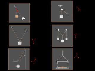


Here are the free body diagrams for the given systems: 1. Axle of bicycle wheel: F_app R_1 R_2 2. Propped cantilever: W_1 W_2 R 3. Neoprene pad bearing functions like a roller support. 4. Circled part of building: W R_1 R_2 R_3 5. Dam: W_water R


