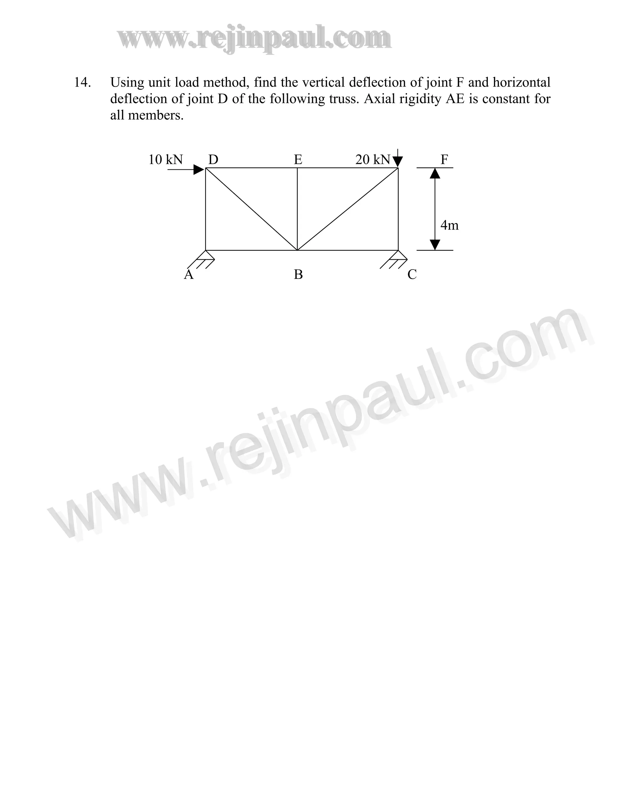
SlideShare a Scribd company logo
1 of 18
Download to read offline
www.rejinpaul.com
www.rejinpaul.com
PART A – 2 MARKS QUESTIONS
UNIT -I
1. Define strain energy density.
2. State Maxwell’s reciprocal theorem.
3. State Castigliano’s theorem to find slope and deflection in a beam.
4. What is meant by strain energy stored in a structure?
5. Find the expression for the strain energy due to bending moment of a simply
supported beam carrying a load W’ spread over its entire length uniformly.
6. What is the strain energy due to (a) axial stress and (b) bending moment?
7. What is strain energy stored by a member subjected to a tensile force?
8. Write the principle of virtual work equation for deflection due to bending.
8. What is Williot diagram?
9. State Engessor’s Theorems.
10. Write down the three moment equation for two equal span continuous beam
simply supported at the ends and carrying two point loads at the middle of
each span. The span is L each.
11. What are the disadvantages of fixed beams?
12. Define degree of static indeterminacy of a structure.
13. Write the three moment equation, stating all the variables used.
14. Explain the effect of settlement of supports in a continuous beam.
15. Draw the shape of the BMD for a fixed beam having end moments – M in
one support and + M in the other.
16. State the principle of virtual work.
17. State the Maxwell reciprocal theorem.
18. Explain the “Modulus of resilience” of a material.
19. State the Castigliano’s Theorem.
www.rejinpaul.comwww.rejinpaul.com
www.rejinpaul.com
www.rejinpaul.com
UNIT – II
1. A cantilever of length 6 m carries a point load of 48 KN at its centre. The
cantilever is propped rigidly at the free end. Determine the reaction at the
rigid prop.
2. A fixed beam AB of length 3 m is having moment of inertia 1 = 3 x 10⁶
mm4
the support B sinks down by 3 mm. If E = 2 x 10⁵
N/mm2,
find the fixing
moments.
3. What is indeterminate beam?
4. What is meant by point of contra flexure?
5. A simply supported beam of span I carries a uniformly distributed load of W
per metre length. The beam was propped at the middle of the span. Find the
amount, by which the prop should yield, in order to make all the three
reactions equal.
6. State the theorem of three moments.
7. Draw the bending moment and shear force diagrams for a fixed beam with a
point load W at the centre.
8. Write down the three moment equations for a propped cantilever beam
carrying a point load at midspan.
9. What are the methods of analysis of continuous beams?
10. What is Williot – Mohr’s diagram?
www.rejinpaul.comwww.rejinpaul.com
www.rejinpaul.com
www.rejinpaul.com
UNIT – III
1. State middle third rule.
2. Write four assumptions made in Euler’s theory of columns.
3. Explain how the Euler’s formula for a mild steel column is not valid, when
the slenderness ratio is less than 80.
4. State any four assumptions made in Lame’s theory.
5. What is slenderness ratio of a column?
6. A Solid round column 3 m long and 50 mm in diameter is used as a short
column with both ends hinged. Determine the Euler’s crippling load for the
column.
E = 200 kN/mm2
.
7. Write down Rankine – Gordon formula for eccentrically loaded columns.
8. What is compound cylinder?
11. How is the failure of thick cylinder is different from that of a thin cylinder?
12. Distinguish between thin and thick cylinder.
13. Explain the Lame’s theory of thick cylinders.
14. What is buckling load?
15. What are the assumptions made in Euler’s Theory?
16. What is the middle third rule?
17. What are the assumptions in Euler’s theory of columns?
17. Distinguish between thick and thin cylinders.
18. What are the limitations of Euler’s theory of columns?
19. What are Emphrical equations?
www.rejinpaul.comwww.rejinpaul.com
www.rejinpaul.com
www.rejinpaul.com
UNIT – IV
1. What is meant by stress tensor?
2. State principal strain theory.
3. State Rankine’s Theory of failure.
4. What is principal plane, principal stress?
5. Write down the formula for the shear stress on the octahedron plane.
6. State Von Mise’s theory of failure.
7. State the principal stress theory. For what type of material this theory is
applicable.
8. UU and VV is a set of axes passing through the centroid G and inclined at an
angle θ (measured anticlockwise) to the x-y co-ordinate. Write expressions
for IUU and IVV in terms of Ixx, Iyy and Ixy.
9. What is deviatric stress tensor?
10. What is shear centre?
11. What is stress invariant?
12. State any four theories of failure.
13. Explain the relationship between the plane of maximum shear with principal
planes.
14. Explain the Vonmiser’s theory of failure.
15. Differentiate between spherical and deviatoric components of stress tensor.
16. What is meant by volumetric strain?
www.rejinpaul.comwww.rejinpaul.com
www.rejinpaul.com
www.rejinpaul.com
UNIT – V
1. State Winkler bach formula.
2. What is principal moment of inertia?
3. What is unsymmetrical bending?
4 Define unsymmetrical bending.
5. Define: Shear centre.
6. Explain the term “shear flow”.
7. Define ‘Fatigue’.
8. What is meant by fatigue failure?
www.rejinpaul.comwww.rejinpaul.com
www.rejinpaul.com
www.rejinpaul.com
UNIT - I
1. i) Derive a relation for strain energy due to shear force.
ii) Derive the relation for minimum defection of a simply supported
beam with uniformity distributed load over entire span. Use strain energy
method.
2. Determine the deflection of the beam given in Fig. Use principal of virtual
work.
W
L/2
A
B C
3. Find the deflection at one third point from left end of the simply supported
beam of span 6 m subjected to uniformly distributed load of 20 kN/m by strain
energy principle.
4. Find the deflection at E in the truss showh in Fig. 1. Areas of members are
given in brackets in square cm. Assume E = 2 x 10⁵
N/mm2
,
3 m
D
(A)
(6) (6) (6) (6)
(A) E (A)
A 3m 3m B
20 KN
5. i) Derive a relation for strain energy due to torsion.
www.rejinpaul.comwww.rejinpaul.com
www.rejinpaul.com
www.rejinpaul.com
ii) A hollow shaft having the external diameter, twice the internal
diameter, subjected to a pure torque, attains a maximum shear stress τ .
Show that The strain energy stored per unit volume of the shaft is 5τ2
/ 16G.
Such a shaft Is required to transmit 4500 kW at 110 r.p.m. with
uniform torque, the maximum stress not exceeding 70 MN/m2
. Calculate the
shaft diameter and the energy stored per m 3
when transmitting this power
G =83 GN/ m2
.
6. A simply supported beam of span 8 m carries a udl of 4 kN/m over the entire
span and two point loads of 2 kN at 2 m from each support. Find the mid-
span deflection using strain energy method. E = 200 kN/mm2
, I = 16 x 108
mm4
.
7. (i) Derive the expression for strain energy due to bending.
(ii) Derive the expression for strain energy due to torsion.
8. Calculate the strain energy stored in a cantilever beam of 4 m span, carrying
a point load 10 kN at free end. Take EI = 25000 KNm2
.
9. Find the deflection at mild span of a simply supported beam carrying an
uniformly distributed load of 2 KN/m over the entire span using principal of
virtual work. Take span = 5 m; EI = 20000 KN/m2
.
10. A simply supported beam of length 10 m is subjected to udl. 10 kN/m over
the left half of the span and a concentrated load 4 kN, 2.5 m from the right
support. Find bending strain energy. Flexural rigidity is uniform and equal to
EI.
11. State and explain the Engesser’s theorem and Castigliano’s theorem.
www.rejinpaul.comwww.rejinpaul.com
www.rejinpaul.com
www.rejinpaul.com
UNIT - II
1. A simply supported beam of span 10 m carries a uniformly distributed load
1153 N per unit length. The beam is propped at the middle of the span.
Find the amount by which the prop should yield, in order to make all the
three reactions equal. Take E =2 x 10⁵
N/mm2
and I for beam = 105
mm4
.
2. A fixed beam AB of length 6 m carries point loads of 160 KN and 120 KN at a
distance of 2 m and 4 m from the left end A. Find the fixed end moments and
the reactions at the supports. Draw BM and SF diagrams.
3. Find the support moments and reactions in a fixed beam of span of 9 m. it is
subjected to concentrated loads of 36 KN and 54 KN at 3 m and 6 m from
left Support respectively. Also draw shear force and bending moment
diagrams.
4. A continuous beam ABCD is simply supported at A, B, C and D. AB = BC
=CD = 4 m. Span AB carries a load of 24 KN at 3 m from A. Span BC
carries an uniformly distributed load of 24 KN/m. Span carries a central
concentrated load of 48 KN. Draw shear force and bending moment
diagrams.
5. Draw shear force and bending moment diagram for a simply supported beam
with a uniformly distributed load over entire span and propped at the
centre. Also derive relations for slope at the ends and maximum and support
reactions.
6. A fixed beam of ACB of span 6 m is carrying a uniformly distributed load of
4 KN/m over the left half of the span AC. Find the fixing moments and
support reactions.
7. A fixed beam AB of length 6 m carries point loads of 200 kN and 150 kN at
distance of 2mm and 4m, respectively from the left support A. Find the fixed
end moments and the reactions as the support. Draw the BM and SF diagrams.
8. A continuous beam ABC has two spans AB and BC of length 4 m and 6 m
simply supported at A, B and C. the beam carries a udl of 60 kN/m on the
span AB and 100 kN/m on the span BC. Determine the support moments at A,
B and C. Draw the BM and SF diagrams. Use theorems of three moments.
www.rejinpaul.comwww.rejinpaul.com
www.rejinpaul.com
www.rejinpaul.com
9. Analyse the beam shown in Fig.
60 kN
10 kN/m
A C
B
3m 3m 6m
10. Analyze beam shown in Fig. EI = constant. Draw the bending moment
diagram.
300 kN 300 kN
A B
2m 2m 2m
11. A beam AB of span 8 m fixed at ends carries point loads of 10 KN, 30 kN and
10 kN at 2 m, 5 m and 6 m respectively from the left end. EI = 1.72 x 10¹⁰
KN/mm2
. Find the fixed end moments at A and B. Also find the
deflection under the loads and maximum deflection.
12. A continuous beam ABC consists of two consecutive spans AB and BC 4 m
each and carrying an UDL of 60 KN/m. The end A is fixed and C is simply
supported. Find the support moments by using three moment equation.
13. Using the theorem of three moments draw the shear force and bending
moment diagrams for the following continuous beam.
4 kN/m 6 kN 8 kN
A B C B
4m 2m 1m 1m 3m
www.rejinpaul.comwww.rejinpaul.com
www.rejinpaul.com
www.rejinpaul.com
14. Using unit load method, find the vertical deflection of joint F and horizontal
deflection of joint D of the following truss. Axial rigidity AE is constant for
all members.
10 kN D E 20 kN F
4m
A B C
www.rejinpaul.comwww.rejinpaul.com
www.rejinpaul.com
www.rejinpaul.com
UNIT – III
1. Derive an expression for crippling load when one end of the column is fixed
and the other end is free.
2. Calculated the Euler’s critical load for a strut of T-section. the flange width
being 10 cm, overall depth 8 cm and both flange and stem 1 cm thick. the strut is 3
m long and is built in at both ends. Take E = 2 x 10 N/mm3
.
3. Find the Euler’s critical load for a cast iron hollow column of external
diameter 200 mm diameter, 25 mm thick and of length 6 m hinged at both ends. E
= 0.8 x 10⁴
N/mm2
. Compare Euler’s load with Rankine’s critical load. Assume fc
=550 N/mm2
and α =1/1600. Find the length of column at which both critical
loads are equal.
4. Derive the Euler’s buckling load for a column with both ends hinged.
5. Find the ratio of buckling strength of a solid column to that of a hollow
column of the same material and having the same cross-sectional area. the internal
diameter of the hollow column is half of its external diameter. Both the columns
are hinged and the same length.
6. i) A pipe of 400 mm internal diameter and 100 mm thick contains a fluid at a
pressure of 10 N/mm2
Find maximum and minimum hoop stress across the section.
Also sketch the stress distribution.
ii) Find the thickness of steel cylindrical shell of internal diameter 200 mm
to withstand an internal pressure of 35 N/mm2
. Maximum hoop stress in the
section not to exceed 120 N/mm2
.
7. A ‘T’ section 150 mm x 120 mm x 20 mm is used as a strut of 4 m long with
hinged at its both ends. Calculate the Crippling load, if Young’s modulus for the
materials is 200 GPa.
8. A steel cylinder is 1 m inside diameter and is to be designed for an internal
pressure of 8 MN/m2
. Calculate the thickness if the maximum shearing stress is not
to exceed 35 MN/m2
. Calculate the increase in volume, due to working pressure, if
the cylinder is 6 m long with closed ends. E = 200 GN/ m2
, Poisson’s ratio = 1/3.
9. The internal and external diameters of a thick cylinder are 80 mm and 120
mm, respectively. It is subjected to an external pressure of 40 N/mm2
when the
www.rejinpaul.comwww.rejinpaul.com
www.rejinpaul.com
www.rejinpaul.com
internal pressure is 120 N/mm2
. Find the circumferential stress at the external and
internal surface and determine the radial and circumferential stresses at the mean
radius.
10. Derive the expression for buckling load of a long column fixed at once end
and Hinged at the other end.
11. Find the greatest length of mild steel bar 25 mm x 25 mm in cross-section
which can be used as compression member with one end fixed and the other end
free to carry a working load of 35 kN. Allow a factor of safety of 4. Take α =
1__ and f c = 320 N/mm2
. 7500
12. Find the thickness of metal necessary for a steel cylinder of internal diameter
200 mm to withstand an internal pressure of 50 N/mm2
. The maximum hoop stress
in the section is not to exceed 150 N/mm2
. Assume thick cylinder.
13. Derive the expression for buckling load of a column fixed at one end and
free at the other end.
14. A hollow cylinder cast iron column is 4 m long and fixed at the ends. Design
the column to carry an axial load of 250 KN. Use Rankineg’s formula and adopt a
factor of safety of 5. The internal diameter may be taken as 0.8 times the external
diameter. Taken Fc = 550 N/mm2
and Rankine’s constant 1__
1600
15. A compound tube is composed of 250 mm internal diameter and 25 mm
thick Shrunk on tube of 250 mm external diameter and 25 mm thick. The radial
pressure at the function is 8 N/mm2
. Find the variation of hoop stress over the wall
of the compound tube.
16. Using Euler’s theory, find the buckling load for the column with following
Boundary conditions: (i) Fixed-free (ii) Fixed-hinged
17. A column with one end hinged and the other end fixed has a length of 5 m
and a hollow cylinder cross section of outer diameter 100 mm and wall thickness
10 mm. If E = 1.60 x 10⁵
N/mm2
and crushing strength σc = 350 N/mm2
, find the
load that the column may carry with a factor of Safety of 2.5 according to Euler
theory and Rankine-Gordon theory. If the Column is hinged on both ends, find the
safe load according to the two Theories.
UNIT – IV
1. The normal stress in two mutually perpendicular directions are 600 N/mm2
and 300 N/mm2
both tensile. The complimentary shear stresses in these directions
www.rejinpaul.comwww.rejinpaul.com
www.rejinpaul.com
www.rejinpaul.com
are of intensity 450 N/mm2
. Find the normal and tangential stresses in the two
planes which are equally inclined to the planes carrying the normal stresses
mentioned above.
2. A solid circular shaft is subjected to a bending moment of 40 KN.m and a
Torque of 10 KN.m Design the diameter of the shaft according to
(i) Maximum principal stress theory
(ii) Maximum shear stress theory
(iii) Maximum strain energy theory.
3. A rectangular block of size 250 mm x 100 mm x 80 mm is subjected to axial
loads as follows. A tensile force of 480 kN in the direction of it’s length. A tensile
force of 900 KN in 250 mm x 80 mm faces. A compressive force of 1000 kN in
250 mm x 100 mm faces. Assuming Poisson’s ratio of 0.25 and modulus of
elasticity of 2 x 10⁵
N/mm2
. Find strain and change in length in each direction.
Also find volumetric strain and change in volume.
4. A rectangular block is subjected to a tensile stress of 100 N/mm2
on one
plane and 50 N/mm2
on a plane at right angles together with a shear stress of 60
N/mm2
on the same plane. Find the direction of principal plan, magnitude and
Nature of principal stresses. Also find the maximum shear stress.
5. In a triaxial stress system, the six components of the stress at a point are
given below: σx = 6 MN/m2
, σy = 5 MN/m2
, σz = 4MN/m2
, τxy = τxy = 1 MN/
m2
, τyz = τyz = 3 MN/m2
, τzx = τxz = 2 MN/m2
. Find the magnitudes of three
principal stresses.
6. In a two dimensional stress system, the direct stresses on two mutually
perpendicular planes are σ and 120 MN/m2
. In addition these planes carry a shear
stress of 40 MN/m2
. Find the value of σ at which the shear strain energy is least. If
failure occurs at this value of the shear strain energy, estimate the elastic limit of
the material in simple tension. Take the factor of safety on elastic limit as 3.
7. A steel drum 600 mm diameter is required to hold gas under a pressure of
3.5N/ mm2
. Calculate the thickness of the drum required according to (i)
maximum principal stress theory and (ii) maximum shear strain energy. The
allowable tensile strength of steel is 120 N/mm2
. E = 200 kN/mm2
, μ = 0.3.
8. A simply supported wooden beam 3 m long supports a total udl of 8 kN. The
Cross-section of the beam is 100 mm x 150 mm. The applied load acts in a plane
www.rejinpaul.comwww.rejinpaul.com
www.rejinpaul.com
www.rejinpaul.com
making an angle of 300
with the vertical plane. Find the maximum bending stress
developed in the beam. Self weight of the beam may be neglected.
9. The state of stress at a point is given by 4 2 3 MPa. Determine the
Principal stresses. 2 6 1
3 1 5
10. Explain any two theories of failure.
11. The state of stress at a point is given by 9 6 3 Mpa. Determine the
Principal stresses. 6 5 2
3 2 4
12. Explain any two theories of failure.
UNIT - V
1. A curved bar is formed of a tube of 120 mm outside diameter and 7.5 mm
Thickness. The centre line of this beam is a circular arc of radius 225 mm. A
www.rejinpaul.comwww.rejinpaul.com
www.rejinpaul.com
www.rejinpaul.com
bending moment of 3 KNm tending to increase curvature of the bar is applied.
Calculate the maximum tensile and compressive stresses set up in the bar.
2. A 80 mm x 80 mm x 10 mm angle section shown in fig is used as a simply
supported beam over a span 2.4 m. It carries a load of 400 N along the line YG,
where G is the centroid of the section. Calculate the stresses at the points A, B
and C of the mild section of the beam Stresses at the points, A, B and C of the mild
section of the beam. Deflection of the beam at the mild section and its direction
with the Load line. Position of the neutral axis. Take E = 200 GN/m2
10 mm Y
A
80 mm
X X
G
10 mm
C
B
K = 80 mm
3. Find the principal moment of inertia of angle section 60 mm x 40 mm x 6
mm.
4. A rectangular section of 80 mm wide and 120 mm deep is subjected to a
bending moment of 12 KNm. The trace of plane of loading is inclined at 450
to YY
axis of the section. Locate neutral axis and find the maximum stress induced
in the section.
5. Find the centroidal principal moments of inertia of a equal angle section 30
x30x10 mm.
6. An equal angle section 150 mm x 150 mm x 10 mm is used as a simply
supported beam of 4 m length is subjected to a vertical load passing through the
centroid. Determine bending stress at point A as shown in Fig.
www.rejinpaul.comwww.rejinpaul.com
www.rejinpaul.com
www.rejinpaul.com
10mm
A
150 mm
B 10 mm
150 mm C
7. An I section of a beam consists of top flange 140 mm x 40 mm and bottom
flange 140 mm x 40 mm. The web is 20 mm x 220 mm. The centre line of the web
is 80 mm from the left edge of the flanges and 60 mm from the right edges of the
flanges. Determine the position of shear centre for the beam.
8. Find the product moment of inertia of a quadrant of circle about the
Perpendicular axes OX and OY as shown in Fig.
Y
• X
R
9. Find the centroidal principal moments of inertia of an equal angle section 30
mm x 30 mm x 10 mm.
10. Determine the principal stresses and principal directions for the following
3D-stress field.
( 30 15 20 )
[σ] = ( 15 20 25 ) Mpa.
( 20 25 40 )
www.rejinpaul.comwww.rejinpaul.com
www.rejinpaul.com
www.rejinpaul.com
11. A three span beam ABCD has spans AL = 6 m, BC = 5 m and CD = 4 m.
All the supports are at same level and also simple supports. The spans AB and BC
are loaded with 9 kN and 8 kN respectively at 2 m from A in span AB and B in
span BC. The span CD’s carrying a UDL of 3 kN/m. If EI is constant throughout
analyse the continuous beam using theorem of three moment and draw the BMD.
12. A beam of constant M.I. spans over 8 m. It is subjected to point loads 5 kN
and 10 kN respectively at left and right quarter points. If E for the beam material is
210 GPa and the permissible deflection at 10 kN load is 25 mm, find the moment
of inertia of the beam section by using energy methods.
13. A Overhanging beam ABC with simple supports at A and B 5 m apart over
hangs by 2 m. It is subjected to a point load of 10 kN acting at the free end C
calculated the slopes at A and B.
14. RSJ 400 x 200 mm is used as a strut with fixed ends for a length of 6 m.
Find the crippling load using Euler’s approach. Assume the thickness of the web
and flanges to be 20 mm and E = 210 GPa.
15. A built column made up of two channels ISJC 200 x 75 mm Back to Back at
100 m was two plates 250 x 10 mm attached on either side. For the channel section
Ixx =11.6 x 10⁶
mm4
; Iyy = 0.84 x 10⁶
mm4
; A = 1777 mm2
, Cxx= 19.7 mm and the
crushing stress is 300 MPa. If the f the column is 6 m and the ends fixed, find the
safe load. Rankines constant is 1/7500.
16. A steel bar of section 60 x 40 mm is arranged as a cantilever projecting
Horizontally 0.6 m beyond a support. The wider face of the section makes 300
with
the horizontal. A load of 500 N is hung from the free end. Locate the Neutral axis
and find the orizontal and vertical deflections of the free end. Also find the
maximum tensile stress. Take E = 2 x 10⁵
MPa.
17. A closed ring made up of 40 mm Ǿ steel bar carries a pull of 20 kN, the line
of action of which passes through its centre. The mean radius of the ring is
10 cm. Find the extreme fiber stresses in the ring.
18. Locate the shear centre for a channel section used with its web vertical. The
size of the channel is 200 x 100 mm with 10 mm uniform thickness. Also draw the
shear flow diagram.
www.rejinpaul.comwww.rejinpaul.com
www.rejinpaul.com
www.rejinpaul.com
19. A shrunk cylinder consists of an inner cylinder of 180 mm and outer
diameter 200 mm and outer cylinder of external diameter of 240 mm and thickness
20 mm. The pressure due to shrinking 8 MPa. If an external of pressure of 60 MPa
acts find the resultant stresses across the wall.
20. A semicircular bar of circular cross section with radius 20 mm is fixed at
one loaded at the other end as shown in the figure. Find the stresses at points A and
B.
21. A cylinder of outer diameter 280 mm and inner diameter 240 mm shrunk
over Another cylinder of outer diameter slightly more than 240 mm and inner
diameter 200 mm to form a compound cylinder. The shrink fit pressure is 10 N/
mm2
. If an internal pressure of 50 N/ mm2
is applied to the compound Cylinder,
find the final stresses across the thickness. Draw sketches showing their variations.
www.rejinpaul.comwww.rejinpaul.com

More Related Content

What's hot

Solution of Chapter- 05 - stresses in beam - Strength of Materials by Singer
Solution of Chapter- 05 - stresses in beam - Strength of Materials by SingerSolution of Chapter- 05 - stresses in beam - Strength of Materials by Singer
Solution of Chapter- 05 - stresses in beam - Strength of Materials by SingerAshiqur Rahman Ziad
 
Young's modulus by single cantilever method
Young's modulus by single cantilever methodYoung's modulus by single cantilever method
Young's modulus by single cantilever methodPraveen Vaidya
 
17422 theory of structures
17422   theory of structures17422   theory of structures
17422 theory of structuressoni_nits
 
Bendingmomentsandshearingforcesinbeams2 100114165451-phpapp01
Bendingmomentsandshearingforcesinbeams2 100114165451-phpapp01Bendingmomentsandshearingforcesinbeams2 100114165451-phpapp01
Bendingmomentsandshearingforcesinbeams2 100114165451-phpapp01Aero Mohamed
 
Bending stresses and shear stresses
Bending stresses and shear stressesBending stresses and shear stresses
Bending stresses and shear stressessumitt6_25730773
 
Strength of materials_I
Strength of materials_IStrength of materials_I
Strength of materials_IPralhad Kore
 
Engineering Mechanics First Year
Engineering Mechanics First YearEngineering Mechanics First Year
Engineering Mechanics First YearEkeeda
 
Forces 7
Forces 7Forces 7
Forces 7Ekeeda
 
A. c. circits
A. c. circitsA. c. circits
A. c. circitsEkeeda
 
Mechanics of solids 1 lecture-1
Mechanics of solids 1 lecture-1Mechanics of solids 1 lecture-1
Mechanics of solids 1 lecture-1EngrKhalid Yousaf
 
Modelling Power Systems 3
Modelling Power Systems 3Modelling Power Systems 3
Modelling Power Systems 3Alex_5991
 
5.2 heating effect of currents
5.2 heating effect of currents5.2 heating effect of currents
5.2 heating effect of currentsPaula Mills
 
(P206)sheet electromagnetic induction_e
(P206)sheet electromagnetic induction_e(P206)sheet electromagnetic induction_e
(P206)sheet electromagnetic induction_eAshutoshPrajapati16
 

What's hot (20)

Solution of Chapter- 05 - stresses in beam - Strength of Materials by Singer
Solution of Chapter- 05 - stresses in beam - Strength of Materials by SingerSolution of Chapter- 05 - stresses in beam - Strength of Materials by Singer
Solution of Chapter- 05 - stresses in beam - Strength of Materials by Singer
 
11 energy methods
11 energy methods11 energy methods
11 energy methods
 
Note stress in beam
Note stress in beamNote stress in beam
Note stress in beam
 
Bef 2
Bef 2Bef 2
Bef 2
 
Young's modulus by single cantilever method
Young's modulus by single cantilever methodYoung's modulus by single cantilever method
Young's modulus by single cantilever method
 
17422 theory of structures
17422   theory of structures17422   theory of structures
17422 theory of structures
 
Stresses in beams
Stresses in beamsStresses in beams
Stresses in beams
 
Bendingmomentsandshearingforcesinbeams2 100114165451-phpapp01
Bendingmomentsandshearingforcesinbeams2 100114165451-phpapp01Bendingmomentsandshearingforcesinbeams2 100114165451-phpapp01
Bendingmomentsandshearingforcesinbeams2 100114165451-phpapp01
 
Bending stresses and shear stresses
Bending stresses and shear stressesBending stresses and shear stresses
Bending stresses and shear stresses
 
Strength of materials_I
Strength of materials_IStrength of materials_I
Strength of materials_I
 
Engineering Mechanics First Year
Engineering Mechanics First YearEngineering Mechanics First Year
Engineering Mechanics First Year
 
Forces 7
Forces 7Forces 7
Forces 7
 
A. c. circits
A. c. circitsA. c. circits
A. c. circits
 
Strength of materials
Strength of materialsStrength of materials
Strength of materials
 
Mechanics of solids 1 lecture-1
Mechanics of solids 1 lecture-1Mechanics of solids 1 lecture-1
Mechanics of solids 1 lecture-1
 
Modelling Power Systems 3
Modelling Power Systems 3Modelling Power Systems 3
Modelling Power Systems 3
 
5.2 heating effect of currents
5.2 heating effect of currents5.2 heating effect of currents
5.2 heating effect of currents
 
Sasoli1
Sasoli1Sasoli1
Sasoli1
 
(P206)sheet electromagnetic induction_e
(P206)sheet electromagnetic induction_e(P206)sheet electromagnetic induction_e
(P206)sheet electromagnetic induction_e
 
Bab8
Bab8Bab8
Bab8
 

Similar to Ce2201 qb1

Ce6306 strength of materials
Ce6306 strength of materialsCe6306 strength of materials
Ce6306 strength of materialspraveen kumar
 
Ce6306 strength of materials
Ce6306 strength of materialsCe6306 strength of materials
Ce6306 strength of materialsSiddhu Siddhu
 
civil ngineering of research for civil engner
civil ngineering of research for civil engnercivil ngineering of research for civil engner
civil ngineering of research for civil engner9866560321sv
 
Shear force & Bending Moment
Shear force & Bending MomentShear force & Bending Moment
Shear force & Bending MomentAbhijeet Pabale
 
B Ending Moments And Shearing Forces In Beams2
B Ending Moments And Shearing Forces In Beams2B Ending Moments And Shearing Forces In Beams2
B Ending Moments And Shearing Forces In Beams2Amr Hamed
 
Shear and Bending Moment in Beams
Shear and Bending Moment in BeamsShear and Bending Moment in Beams
Shear and Bending Moment in BeamsAmr Hamed
 
B Ending Moments And Shearing Forces In Beams2
B Ending Moments And Shearing Forces In Beams2B Ending Moments And Shearing Forces In Beams2
B Ending Moments And Shearing Forces In Beams2Amr Hamed
 
strength of materials
strength of materialsstrength of materials
strength of materialsGowtham Raja
 
Class 12 Cbse Physics Sample Paper 2013 Model 1
Class 12 Cbse Physics Sample Paper 2013 Model 1 Class 12 Cbse Physics Sample Paper 2013 Model 1
Class 12 Cbse Physics Sample Paper 2013 Model 1 Sunaina Rawat
 
Bending and free vibration analysis of isotropic and composite beams
Bending and free vibration analysis of isotropic and composite beamsBending and free vibration analysis of isotropic and composite beams
Bending and free vibration analysis of isotropic and composite beamsSayan Batabyal
 
SA-II Notes.pdf
SA-II  Notes.pdfSA-II  Notes.pdf
SA-II Notes.pdfParandh M
 
Deflection of Beams.pptx......pptx
Deflection of Beams.pptx......pptxDeflection of Beams.pptx......pptx
Deflection of Beams.pptx......pptxKhalilBahrEldin
 
Analysis of Stress and Deflection of Cantilever Beam and its Validation Using...
Analysis of Stress and Deflection of Cantilever Beam and its Validation Using...Analysis of Stress and Deflection of Cantilever Beam and its Validation Using...
Analysis of Stress and Deflection of Cantilever Beam and its Validation Using...IJERA Editor
 
Advanced structures - wing section, beams, bending, shear flow and shear center
Advanced structures - wing section, beams, bending, shear flow and shear centerAdvanced structures - wing section, beams, bending, shear flow and shear center
Advanced structures - wing section, beams, bending, shear flow and shear centerRohan M Ganapathy
 
Bars subjected to multiple loads
Bars subjected to multiple loadsBars subjected to multiple loads
Bars subjected to multiple loadssushma chinta
 

Similar to Ce2201 qb1 (20)

Ce6306 strength of materials
Ce6306 strength of materialsCe6306 strength of materials
Ce6306 strength of materials
 
Ce6306 strength of materials
Ce6306 strength of materialsCe6306 strength of materials
Ce6306 strength of materials
 
civil ngineering of research for civil engner
civil ngineering of research for civil engnercivil ngineering of research for civil engner
civil ngineering of research for civil engner
 
Shear force & Bending Moment
Shear force & Bending MomentShear force & Bending Moment
Shear force & Bending Moment
 
Structural analysis 2 lab manual
Structural analysis 2 lab manualStructural analysis 2 lab manual
Structural analysis 2 lab manual
 
B Ending Moments And Shearing Forces In Beams2
B Ending Moments And Shearing Forces In Beams2B Ending Moments And Shearing Forces In Beams2
B Ending Moments And Shearing Forces In Beams2
 
Shear and Bending Moment in Beams
Shear and Bending Moment in BeamsShear and Bending Moment in Beams
Shear and Bending Moment in Beams
 
B Ending Moments And Shearing Forces In Beams2
B Ending Moments And Shearing Forces In Beams2B Ending Moments And Shearing Forces In Beams2
B Ending Moments And Shearing Forces In Beams2
 
strength of materials
strength of materialsstrength of materials
strength of materials
 
Class 12 Cbse Physics Sample Paper 2013 Model 1
Class 12 Cbse Physics Sample Paper 2013 Model 1 Class 12 Cbse Physics Sample Paper 2013 Model 1
Class 12 Cbse Physics Sample Paper 2013 Model 1
 
Bending and free vibration analysis of isotropic and composite beams
Bending and free vibration analysis of isotropic and composite beamsBending and free vibration analysis of isotropic and composite beams
Bending and free vibration analysis of isotropic and composite beams
 
SA-II Notes.pdf
SA-II  Notes.pdfSA-II  Notes.pdf
SA-II Notes.pdf
 
Deflection of Beams.pptx......pptx
Deflection of Beams.pptx......pptxDeflection of Beams.pptx......pptx
Deflection of Beams.pptx......pptx
 
Analysis of Stress and Deflection of Cantilever Beam and its Validation Using...
Analysis of Stress and Deflection of Cantilever Beam and its Validation Using...Analysis of Stress and Deflection of Cantilever Beam and its Validation Using...
Analysis of Stress and Deflection of Cantilever Beam and its Validation Using...
 
Analysis of Stress and Deflection of Cantilever Beam and its Validation Using...
Analysis of Stress and Deflection of Cantilever Beam and its Validation Using...Analysis of Stress and Deflection of Cantilever Beam and its Validation Using...
Analysis of Stress and Deflection of Cantilever Beam and its Validation Using...
 
5 beams
5 beams5 beams
5 beams
 
5 Beams[1]
5 Beams[1]5 Beams[1]
5 Beams[1]
 
Advanced structures - wing section, beams, bending, shear flow and shear center
Advanced structures - wing section, beams, bending, shear flow and shear centerAdvanced structures - wing section, beams, bending, shear flow and shear center
Advanced structures - wing section, beams, bending, shear flow and shear center
 
MANUAL SAP2000 - VIGAS - CARGAS INTERNAS
MANUAL SAP2000 - VIGAS - CARGAS INTERNASMANUAL SAP2000 - VIGAS - CARGAS INTERNAS
MANUAL SAP2000 - VIGAS - CARGAS INTERNAS
 
Bars subjected to multiple loads
Bars subjected to multiple loadsBars subjected to multiple loads
Bars subjected to multiple loads
 

Recently uploaded

Presiding Officer Training module 2024 lok sabha elections
Presiding Officer Training module 2024 lok sabha electionsPresiding Officer Training module 2024 lok sabha elections
Presiding Officer Training module 2024 lok sabha electionsanshu789521
 
_Math 4-Q4 Week 5.pptx Steps in Collecting Data
_Math 4-Q4 Week 5.pptx Steps in Collecting Data_Math 4-Q4 Week 5.pptx Steps in Collecting Data
_Math 4-Q4 Week 5.pptx Steps in Collecting DataJhengPantaleon
 
Class 11 Legal Studies Ch-1 Concept of State .pdf
Class 11 Legal Studies Ch-1 Concept of State .pdfClass 11 Legal Studies Ch-1 Concept of State .pdf
Class 11 Legal Studies Ch-1 Concept of State .pdfakmcokerachita
 
भारत-रोम व्यापार.pptx, Indo-Roman Trade,
भारत-रोम व्यापार.pptx, Indo-Roman Trade,भारत-रोम व्यापार.pptx, Indo-Roman Trade,
भारत-रोम व्यापार.pptx, Indo-Roman Trade,Virag Sontakke
 
How to Make a Pirate ship Primary Education.pptx
How to Make a Pirate ship Primary Education.pptxHow to Make a Pirate ship Primary Education.pptx
How to Make a Pirate ship Primary Education.pptxmanuelaromero2013
 
Crayon Activity Handout For the Crayon A
Crayon Activity Handout For the Crayon ACrayon Activity Handout For the Crayon A
Crayon Activity Handout For the Crayon AUnboundStockton
 
Organic Name Reactions for the students and aspirants of Chemistry12th.pptx
Organic Name Reactions  for the students and aspirants of Chemistry12th.pptxOrganic Name Reactions  for the students and aspirants of Chemistry12th.pptx
Organic Name Reactions for the students and aspirants of Chemistry12th.pptxVS Mahajan Coaching Centre
 
“Oh GOSH! Reflecting on Hackteria's Collaborative Practices in a Global Do-It...
“Oh GOSH! Reflecting on Hackteria's Collaborative Practices in a Global Do-It...“Oh GOSH! Reflecting on Hackteria's Collaborative Practices in a Global Do-It...
“Oh GOSH! Reflecting on Hackteria's Collaborative Practices in a Global Do-It...Marc Dusseiller Dusjagr
 
Painted Grey Ware.pptx, PGW Culture of India
Painted Grey Ware.pptx, PGW Culture of IndiaPainted Grey Ware.pptx, PGW Culture of India
Painted Grey Ware.pptx, PGW Culture of IndiaVirag Sontakke
 
Software Engineering Methodologies (overview)
Software Engineering Methodologies (overview)Software Engineering Methodologies (overview)
Software Engineering Methodologies (overview)eniolaolutunde
 
Computed Fields and api Depends in the Odoo 17
Computed Fields and api Depends in the Odoo 17Computed Fields and api Depends in the Odoo 17
Computed Fields and api Depends in the Odoo 17Celine George
 
A Critique of the Proposed National Education Policy Reform
A Critique of the Proposed National Education Policy ReformA Critique of the Proposed National Education Policy Reform
A Critique of the Proposed National Education Policy ReformChameera Dedduwage
 
Biting mechanism of poisonous snakes.pdf
Biting mechanism of poisonous snakes.pdfBiting mechanism of poisonous snakes.pdf
Biting mechanism of poisonous snakes.pdfadityarao40181
 
CARE OF CHILD IN INCUBATOR..........pptx
CARE OF CHILD IN INCUBATOR..........pptxCARE OF CHILD IN INCUBATOR..........pptx
CARE OF CHILD IN INCUBATOR..........pptxGaneshChakor2
 
ECONOMIC CONTEXT - LONG FORM TV DRAMA - PPT
ECONOMIC CONTEXT - LONG FORM TV DRAMA - PPTECONOMIC CONTEXT - LONG FORM TV DRAMA - PPT
ECONOMIC CONTEXT - LONG FORM TV DRAMA - PPTiammrhaywood
 
ENGLISH5 QUARTER4 MODULE1 WEEK1-3 How Visual and Multimedia Elements.pptx
ENGLISH5 QUARTER4 MODULE1 WEEK1-3 How Visual and Multimedia Elements.pptxENGLISH5 QUARTER4 MODULE1 WEEK1-3 How Visual and Multimedia Elements.pptx
ENGLISH5 QUARTER4 MODULE1 WEEK1-3 How Visual and Multimedia Elements.pptxAnaBeatriceAblay2
 
Introduction to AI in Higher Education_draft.pptx
Introduction to AI in Higher Education_draft.pptxIntroduction to AI in Higher Education_draft.pptx
Introduction to AI in Higher Education_draft.pptxpboyjonauth
 
History Class XII Ch. 3 Kinship, Caste and Class (1).pptx
History Class XII Ch. 3 Kinship, Caste and Class (1).pptxHistory Class XII Ch. 3 Kinship, Caste and Class (1).pptx
History Class XII Ch. 3 Kinship, Caste and Class (1).pptxsocialsciencegdgrohi
 

Recently uploaded (20)

Presiding Officer Training module 2024 lok sabha elections
Presiding Officer Training module 2024 lok sabha electionsPresiding Officer Training module 2024 lok sabha elections
Presiding Officer Training module 2024 lok sabha elections
 
_Math 4-Q4 Week 5.pptx Steps in Collecting Data
_Math 4-Q4 Week 5.pptx Steps in Collecting Data_Math 4-Q4 Week 5.pptx Steps in Collecting Data
_Math 4-Q4 Week 5.pptx Steps in Collecting Data
 
Class 11 Legal Studies Ch-1 Concept of State .pdf
Class 11 Legal Studies Ch-1 Concept of State .pdfClass 11 Legal Studies Ch-1 Concept of State .pdf
Class 11 Legal Studies Ch-1 Concept of State .pdf
 
TataKelola dan KamSiber Kecerdasan Buatan v022.pdf
TataKelola dan KamSiber Kecerdasan Buatan v022.pdfTataKelola dan KamSiber Kecerdasan Buatan v022.pdf
TataKelola dan KamSiber Kecerdasan Buatan v022.pdf
 
भारत-रोम व्यापार.pptx, Indo-Roman Trade,
भारत-रोम व्यापार.pptx, Indo-Roman Trade,भारत-रोम व्यापार.pptx, Indo-Roman Trade,
भारत-रोम व्यापार.pptx, Indo-Roman Trade,
 
How to Make a Pirate ship Primary Education.pptx
How to Make a Pirate ship Primary Education.pptxHow to Make a Pirate ship Primary Education.pptx
How to Make a Pirate ship Primary Education.pptx
 
Crayon Activity Handout For the Crayon A
Crayon Activity Handout For the Crayon ACrayon Activity Handout For the Crayon A
Crayon Activity Handout For the Crayon A
 
Organic Name Reactions for the students and aspirants of Chemistry12th.pptx
Organic Name Reactions  for the students and aspirants of Chemistry12th.pptxOrganic Name Reactions  for the students and aspirants of Chemistry12th.pptx
Organic Name Reactions for the students and aspirants of Chemistry12th.pptx
 
“Oh GOSH! Reflecting on Hackteria's Collaborative Practices in a Global Do-It...
“Oh GOSH! Reflecting on Hackteria's Collaborative Practices in a Global Do-It...“Oh GOSH! Reflecting on Hackteria's Collaborative Practices in a Global Do-It...
“Oh GOSH! Reflecting on Hackteria's Collaborative Practices in a Global Do-It...
 
Model Call Girl in Tilak Nagar Delhi reach out to us at 🔝9953056974🔝
Model Call Girl in Tilak Nagar Delhi reach out to us at 🔝9953056974🔝Model Call Girl in Tilak Nagar Delhi reach out to us at 🔝9953056974🔝
Model Call Girl in Tilak Nagar Delhi reach out to us at 🔝9953056974🔝
 
Painted Grey Ware.pptx, PGW Culture of India
Painted Grey Ware.pptx, PGW Culture of IndiaPainted Grey Ware.pptx, PGW Culture of India
Painted Grey Ware.pptx, PGW Culture of India
 
Software Engineering Methodologies (overview)
Software Engineering Methodologies (overview)Software Engineering Methodologies (overview)
Software Engineering Methodologies (overview)
 
Computed Fields and api Depends in the Odoo 17
Computed Fields and api Depends in the Odoo 17Computed Fields and api Depends in the Odoo 17
Computed Fields and api Depends in the Odoo 17
 
A Critique of the Proposed National Education Policy Reform
A Critique of the Proposed National Education Policy ReformA Critique of the Proposed National Education Policy Reform
A Critique of the Proposed National Education Policy Reform
 
Biting mechanism of poisonous snakes.pdf
Biting mechanism of poisonous snakes.pdfBiting mechanism of poisonous snakes.pdf
Biting mechanism of poisonous snakes.pdf
 
CARE OF CHILD IN INCUBATOR..........pptx
CARE OF CHILD IN INCUBATOR..........pptxCARE OF CHILD IN INCUBATOR..........pptx
CARE OF CHILD IN INCUBATOR..........pptx
 
ECONOMIC CONTEXT - LONG FORM TV DRAMA - PPT
ECONOMIC CONTEXT - LONG FORM TV DRAMA - PPTECONOMIC CONTEXT - LONG FORM TV DRAMA - PPT
ECONOMIC CONTEXT - LONG FORM TV DRAMA - PPT
 
ENGLISH5 QUARTER4 MODULE1 WEEK1-3 How Visual and Multimedia Elements.pptx
ENGLISH5 QUARTER4 MODULE1 WEEK1-3 How Visual and Multimedia Elements.pptxENGLISH5 QUARTER4 MODULE1 WEEK1-3 How Visual and Multimedia Elements.pptx
ENGLISH5 QUARTER4 MODULE1 WEEK1-3 How Visual and Multimedia Elements.pptx
 
Introduction to AI in Higher Education_draft.pptx
Introduction to AI in Higher Education_draft.pptxIntroduction to AI in Higher Education_draft.pptx
Introduction to AI in Higher Education_draft.pptx
 
History Class XII Ch. 3 Kinship, Caste and Class (1).pptx
History Class XII Ch. 3 Kinship, Caste and Class (1).pptxHistory Class XII Ch. 3 Kinship, Caste and Class (1).pptx
History Class XII Ch. 3 Kinship, Caste and Class (1).pptx
 

Ce2201 qb1

  • 1. www.rejinpaul.com www.rejinpaul.com PART A – 2 MARKS QUESTIONS UNIT -I 1. Define strain energy density. 2. State Maxwell’s reciprocal theorem. 3. State Castigliano’s theorem to find slope and deflection in a beam. 4. What is meant by strain energy stored in a structure? 5. Find the expression for the strain energy due to bending moment of a simply supported beam carrying a load W’ spread over its entire length uniformly. 6. What is the strain energy due to (a) axial stress and (b) bending moment? 7. What is strain energy stored by a member subjected to a tensile force? 8. Write the principle of virtual work equation for deflection due to bending. 8. What is Williot diagram? 9. State Engessor’s Theorems. 10. Write down the three moment equation for two equal span continuous beam simply supported at the ends and carrying two point loads at the middle of each span. The span is L each. 11. What are the disadvantages of fixed beams? 12. Define degree of static indeterminacy of a structure. 13. Write the three moment equation, stating all the variables used. 14. Explain the effect of settlement of supports in a continuous beam. 15. Draw the shape of the BMD for a fixed beam having end moments – M in one support and + M in the other. 16. State the principle of virtual work. 17. State the Maxwell reciprocal theorem. 18. Explain the “Modulus of resilience” of a material. 19. State the Castigliano’s Theorem. www.rejinpaul.comwww.rejinpaul.com
  • 2. www.rejinpaul.com www.rejinpaul.com UNIT – II 1. A cantilever of length 6 m carries a point load of 48 KN at its centre. The cantilever is propped rigidly at the free end. Determine the reaction at the rigid prop. 2. A fixed beam AB of length 3 m is having moment of inertia 1 = 3 x 106 mm4 the support B sinks down by 3 mm. If E = 2 x 10⁵ N/mm2, find the fixing moments. 3. What is indeterminate beam? 4. What is meant by point of contra flexure? 5. A simply supported beam of span I carries a uniformly distributed load of W per metre length. The beam was propped at the middle of the span. Find the amount, by which the prop should yield, in order to make all the three reactions equal. 6. State the theorem of three moments. 7. Draw the bending moment and shear force diagrams for a fixed beam with a point load W at the centre. 8. Write down the three moment equations for a propped cantilever beam carrying a point load at midspan. 9. What are the methods of analysis of continuous beams? 10. What is Williot – Mohr’s diagram? www.rejinpaul.comwww.rejinpaul.com
  • 3. www.rejinpaul.com www.rejinpaul.com UNIT – III 1. State middle third rule. 2. Write four assumptions made in Euler’s theory of columns. 3. Explain how the Euler’s formula for a mild steel column is not valid, when the slenderness ratio is less than 80. 4. State any four assumptions made in Lame’s theory. 5. What is slenderness ratio of a column? 6. A Solid round column 3 m long and 50 mm in diameter is used as a short column with both ends hinged. Determine the Euler’s crippling load for the column. E = 200 kN/mm2 . 7. Write down Rankine – Gordon formula for eccentrically loaded columns. 8. What is compound cylinder? 11. How is the failure of thick cylinder is different from that of a thin cylinder? 12. Distinguish between thin and thick cylinder. 13. Explain the Lame’s theory of thick cylinders. 14. What is buckling load? 15. What are the assumptions made in Euler’s Theory? 16. What is the middle third rule? 17. What are the assumptions in Euler’s theory of columns? 17. Distinguish between thick and thin cylinders. 18. What are the limitations of Euler’s theory of columns? 19. What are Emphrical equations? www.rejinpaul.comwww.rejinpaul.com
  • 4. www.rejinpaul.com www.rejinpaul.com UNIT – IV 1. What is meant by stress tensor? 2. State principal strain theory. 3. State Rankine’s Theory of failure. 4. What is principal plane, principal stress? 5. Write down the formula for the shear stress on the octahedron plane. 6. State Von Mise’s theory of failure. 7. State the principal stress theory. For what type of material this theory is applicable. 8. UU and VV is a set of axes passing through the centroid G and inclined at an angle θ (measured anticlockwise) to the x-y co-ordinate. Write expressions for IUU and IVV in terms of Ixx, Iyy and Ixy. 9. What is deviatric stress tensor? 10. What is shear centre? 11. What is stress invariant? 12. State any four theories of failure. 13. Explain the relationship between the plane of maximum shear with principal planes. 14. Explain the Vonmiser’s theory of failure. 15. Differentiate between spherical and deviatoric components of stress tensor. 16. What is meant by volumetric strain? www.rejinpaul.comwww.rejinpaul.com
  • 5. www.rejinpaul.com www.rejinpaul.com UNIT – V 1. State Winkler bach formula. 2. What is principal moment of inertia? 3. What is unsymmetrical bending? 4 Define unsymmetrical bending. 5. Define: Shear centre. 6. Explain the term “shear flow”. 7. Define ‘Fatigue’. 8. What is meant by fatigue failure? www.rejinpaul.comwww.rejinpaul.com
  • 6. www.rejinpaul.com www.rejinpaul.com UNIT - I 1. i) Derive a relation for strain energy due to shear force. ii) Derive the relation for minimum defection of a simply supported beam with uniformity distributed load over entire span. Use strain energy method. 2. Determine the deflection of the beam given in Fig. Use principal of virtual work. W L/2 A B C 3. Find the deflection at one third point from left end of the simply supported beam of span 6 m subjected to uniformly distributed load of 20 kN/m by strain energy principle. 4. Find the deflection at E in the truss showh in Fig. 1. Areas of members are given in brackets in square cm. Assume E = 2 x 10⁵ N/mm2 , 3 m D (A) (6) (6) (6) (6) (A) E (A) A 3m 3m B 20 KN 5. i) Derive a relation for strain energy due to torsion. www.rejinpaul.comwww.rejinpaul.com
  • 7. www.rejinpaul.com www.rejinpaul.com ii) A hollow shaft having the external diameter, twice the internal diameter, subjected to a pure torque, attains a maximum shear stress τ . Show that The strain energy stored per unit volume of the shaft is 5τ2 / 16G. Such a shaft Is required to transmit 4500 kW at 110 r.p.m. with uniform torque, the maximum stress not exceeding 70 MN/m2 . Calculate the shaft diameter and the energy stored per m 3 when transmitting this power G =83 GN/ m2 . 6. A simply supported beam of span 8 m carries a udl of 4 kN/m over the entire span and two point loads of 2 kN at 2 m from each support. Find the mid- span deflection using strain energy method. E = 200 kN/mm2 , I = 16 x 108 mm4 . 7. (i) Derive the expression for strain energy due to bending. (ii) Derive the expression for strain energy due to torsion. 8. Calculate the strain energy stored in a cantilever beam of 4 m span, carrying a point load 10 kN at free end. Take EI = 25000 KNm2 . 9. Find the deflection at mild span of a simply supported beam carrying an uniformly distributed load of 2 KN/m over the entire span using principal of virtual work. Take span = 5 m; EI = 20000 KN/m2 . 10. A simply supported beam of length 10 m is subjected to udl. 10 kN/m over the left half of the span and a concentrated load 4 kN, 2.5 m from the right support. Find bending strain energy. Flexural rigidity is uniform and equal to EI. 11. State and explain the Engesser’s theorem and Castigliano’s theorem. www.rejinpaul.comwww.rejinpaul.com
  • 8. www.rejinpaul.com www.rejinpaul.com UNIT - II 1. A simply supported beam of span 10 m carries a uniformly distributed load 1153 N per unit length. The beam is propped at the middle of the span. Find the amount by which the prop should yield, in order to make all the three reactions equal. Take E =2 x 10⁵ N/mm2 and I for beam = 105 mm4 . 2. A fixed beam AB of length 6 m carries point loads of 160 KN and 120 KN at a distance of 2 m and 4 m from the left end A. Find the fixed end moments and the reactions at the supports. Draw BM and SF diagrams. 3. Find the support moments and reactions in a fixed beam of span of 9 m. it is subjected to concentrated loads of 36 KN and 54 KN at 3 m and 6 m from left Support respectively. Also draw shear force and bending moment diagrams. 4. A continuous beam ABCD is simply supported at A, B, C and D. AB = BC =CD = 4 m. Span AB carries a load of 24 KN at 3 m from A. Span BC carries an uniformly distributed load of 24 KN/m. Span carries a central concentrated load of 48 KN. Draw shear force and bending moment diagrams. 5. Draw shear force and bending moment diagram for a simply supported beam with a uniformly distributed load over entire span and propped at the centre. Also derive relations for slope at the ends and maximum and support reactions. 6. A fixed beam of ACB of span 6 m is carrying a uniformly distributed load of 4 KN/m over the left half of the span AC. Find the fixing moments and support reactions. 7. A fixed beam AB of length 6 m carries point loads of 200 kN and 150 kN at distance of 2mm and 4m, respectively from the left support A. Find the fixed end moments and the reactions as the support. Draw the BM and SF diagrams. 8. A continuous beam ABC has two spans AB and BC of length 4 m and 6 m simply supported at A, B and C. the beam carries a udl of 60 kN/m on the span AB and 100 kN/m on the span BC. Determine the support moments at A, B and C. Draw the BM and SF diagrams. Use theorems of three moments. www.rejinpaul.comwww.rejinpaul.com
  • 9. www.rejinpaul.com www.rejinpaul.com 9. Analyse the beam shown in Fig. 60 kN 10 kN/m A C B 3m 3m 6m 10. Analyze beam shown in Fig. EI = constant. Draw the bending moment diagram. 300 kN 300 kN A B 2m 2m 2m 11. A beam AB of span 8 m fixed at ends carries point loads of 10 KN, 30 kN and 10 kN at 2 m, 5 m and 6 m respectively from the left end. EI = 1.72 x 10¹⁰ KN/mm2 . Find the fixed end moments at A and B. Also find the deflection under the loads and maximum deflection. 12. A continuous beam ABC consists of two consecutive spans AB and BC 4 m each and carrying an UDL of 60 KN/m. The end A is fixed and C is simply supported. Find the support moments by using three moment equation. 13. Using the theorem of three moments draw the shear force and bending moment diagrams for the following continuous beam. 4 kN/m 6 kN 8 kN A B C B 4m 2m 1m 1m 3m www.rejinpaul.comwww.rejinpaul.com
  • 10. www.rejinpaul.com www.rejinpaul.com 14. Using unit load method, find the vertical deflection of joint F and horizontal deflection of joint D of the following truss. Axial rigidity AE is constant for all members. 10 kN D E 20 kN F 4m A B C www.rejinpaul.comwww.rejinpaul.com
  • 11. www.rejinpaul.com www.rejinpaul.com UNIT – III 1. Derive an expression for crippling load when one end of the column is fixed and the other end is free. 2. Calculated the Euler’s critical load for a strut of T-section. the flange width being 10 cm, overall depth 8 cm and both flange and stem 1 cm thick. the strut is 3 m long and is built in at both ends. Take E = 2 x 10 N/mm3 . 3. Find the Euler’s critical load for a cast iron hollow column of external diameter 200 mm diameter, 25 mm thick and of length 6 m hinged at both ends. E = 0.8 x 10⁴ N/mm2 . Compare Euler’s load with Rankine’s critical load. Assume fc =550 N/mm2 and α =1/1600. Find the length of column at which both critical loads are equal. 4. Derive the Euler’s buckling load for a column with both ends hinged. 5. Find the ratio of buckling strength of a solid column to that of a hollow column of the same material and having the same cross-sectional area. the internal diameter of the hollow column is half of its external diameter. Both the columns are hinged and the same length. 6. i) A pipe of 400 mm internal diameter and 100 mm thick contains a fluid at a pressure of 10 N/mm2 Find maximum and minimum hoop stress across the section. Also sketch the stress distribution. ii) Find the thickness of steel cylindrical shell of internal diameter 200 mm to withstand an internal pressure of 35 N/mm2 . Maximum hoop stress in the section not to exceed 120 N/mm2 . 7. A ‘T’ section 150 mm x 120 mm x 20 mm is used as a strut of 4 m long with hinged at its both ends. Calculate the Crippling load, if Young’s modulus for the materials is 200 GPa. 8. A steel cylinder is 1 m inside diameter and is to be designed for an internal pressure of 8 MN/m2 . Calculate the thickness if the maximum shearing stress is not to exceed 35 MN/m2 . Calculate the increase in volume, due to working pressure, if the cylinder is 6 m long with closed ends. E = 200 GN/ m2 , Poisson’s ratio = 1/3. 9. The internal and external diameters of a thick cylinder are 80 mm and 120 mm, respectively. It is subjected to an external pressure of 40 N/mm2 when the www.rejinpaul.comwww.rejinpaul.com
  • 12. www.rejinpaul.com www.rejinpaul.com internal pressure is 120 N/mm2 . Find the circumferential stress at the external and internal surface and determine the radial and circumferential stresses at the mean radius. 10. Derive the expression for buckling load of a long column fixed at once end and Hinged at the other end. 11. Find the greatest length of mild steel bar 25 mm x 25 mm in cross-section which can be used as compression member with one end fixed and the other end free to carry a working load of 35 kN. Allow a factor of safety of 4. Take α = 1__ and f c = 320 N/mm2 . 7500 12. Find the thickness of metal necessary for a steel cylinder of internal diameter 200 mm to withstand an internal pressure of 50 N/mm2 . The maximum hoop stress in the section is not to exceed 150 N/mm2 . Assume thick cylinder. 13. Derive the expression for buckling load of a column fixed at one end and free at the other end. 14. A hollow cylinder cast iron column is 4 m long and fixed at the ends. Design the column to carry an axial load of 250 KN. Use Rankineg’s formula and adopt a factor of safety of 5. The internal diameter may be taken as 0.8 times the external diameter. Taken Fc = 550 N/mm2 and Rankine’s constant 1__ 1600 15. A compound tube is composed of 250 mm internal diameter and 25 mm thick Shrunk on tube of 250 mm external diameter and 25 mm thick. The radial pressure at the function is 8 N/mm2 . Find the variation of hoop stress over the wall of the compound tube. 16. Using Euler’s theory, find the buckling load for the column with following Boundary conditions: (i) Fixed-free (ii) Fixed-hinged 17. A column with one end hinged and the other end fixed has a length of 5 m and a hollow cylinder cross section of outer diameter 100 mm and wall thickness 10 mm. If E = 1.60 x 10⁵ N/mm2 and crushing strength σc = 350 N/mm2 , find the load that the column may carry with a factor of Safety of 2.5 according to Euler theory and Rankine-Gordon theory. If the Column is hinged on both ends, find the safe load according to the two Theories. UNIT – IV 1. The normal stress in two mutually perpendicular directions are 600 N/mm2 and 300 N/mm2 both tensile. The complimentary shear stresses in these directions www.rejinpaul.comwww.rejinpaul.com
  • 13. www.rejinpaul.com www.rejinpaul.com are of intensity 450 N/mm2 . Find the normal and tangential stresses in the two planes which are equally inclined to the planes carrying the normal stresses mentioned above. 2. A solid circular shaft is subjected to a bending moment of 40 KN.m and a Torque of 10 KN.m Design the diameter of the shaft according to (i) Maximum principal stress theory (ii) Maximum shear stress theory (iii) Maximum strain energy theory. 3. A rectangular block of size 250 mm x 100 mm x 80 mm is subjected to axial loads as follows. A tensile force of 480 kN in the direction of it’s length. A tensile force of 900 KN in 250 mm x 80 mm faces. A compressive force of 1000 kN in 250 mm x 100 mm faces. Assuming Poisson’s ratio of 0.25 and modulus of elasticity of 2 x 10⁵ N/mm2 . Find strain and change in length in each direction. Also find volumetric strain and change in volume. 4. A rectangular block is subjected to a tensile stress of 100 N/mm2 on one plane and 50 N/mm2 on a plane at right angles together with a shear stress of 60 N/mm2 on the same plane. Find the direction of principal plan, magnitude and Nature of principal stresses. Also find the maximum shear stress. 5. In a triaxial stress system, the six components of the stress at a point are given below: σx = 6 MN/m2 , σy = 5 MN/m2 , σz = 4MN/m2 , τxy = τxy = 1 MN/ m2 , τyz = τyz = 3 MN/m2 , τzx = τxz = 2 MN/m2 . Find the magnitudes of three principal stresses. 6. In a two dimensional stress system, the direct stresses on two mutually perpendicular planes are σ and 120 MN/m2 . In addition these planes carry a shear stress of 40 MN/m2 . Find the value of σ at which the shear strain energy is least. If failure occurs at this value of the shear strain energy, estimate the elastic limit of the material in simple tension. Take the factor of safety on elastic limit as 3. 7. A steel drum 600 mm diameter is required to hold gas under a pressure of 3.5N/ mm2 . Calculate the thickness of the drum required according to (i) maximum principal stress theory and (ii) maximum shear strain energy. The allowable tensile strength of steel is 120 N/mm2 . E = 200 kN/mm2 , μ = 0.3. 8. A simply supported wooden beam 3 m long supports a total udl of 8 kN. The Cross-section of the beam is 100 mm x 150 mm. The applied load acts in a plane www.rejinpaul.comwww.rejinpaul.com
  • 14. www.rejinpaul.com www.rejinpaul.com making an angle of 300 with the vertical plane. Find the maximum bending stress developed in the beam. Self weight of the beam may be neglected. 9. The state of stress at a point is given by 4 2 3 MPa. Determine the Principal stresses. 2 6 1 3 1 5 10. Explain any two theories of failure. 11. The state of stress at a point is given by 9 6 3 Mpa. Determine the Principal stresses. 6 5 2 3 2 4 12. Explain any two theories of failure. UNIT - V 1. A curved bar is formed of a tube of 120 mm outside diameter and 7.5 mm Thickness. The centre line of this beam is a circular arc of radius 225 mm. A www.rejinpaul.comwww.rejinpaul.com
  • 15. www.rejinpaul.com www.rejinpaul.com bending moment of 3 KNm tending to increase curvature of the bar is applied. Calculate the maximum tensile and compressive stresses set up in the bar. 2. A 80 mm x 80 mm x 10 mm angle section shown in fig is used as a simply supported beam over a span 2.4 m. It carries a load of 400 N along the line YG, where G is the centroid of the section. Calculate the stresses at the points A, B and C of the mild section of the beam Stresses at the points, A, B and C of the mild section of the beam. Deflection of the beam at the mild section and its direction with the Load line. Position of the neutral axis. Take E = 200 GN/m2 10 mm Y A 80 mm X X G 10 mm C B K = 80 mm 3. Find the principal moment of inertia of angle section 60 mm x 40 mm x 6 mm. 4. A rectangular section of 80 mm wide and 120 mm deep is subjected to a bending moment of 12 KNm. The trace of plane of loading is inclined at 450 to YY axis of the section. Locate neutral axis and find the maximum stress induced in the section. 5. Find the centroidal principal moments of inertia of a equal angle section 30 x30x10 mm. 6. An equal angle section 150 mm x 150 mm x 10 mm is used as a simply supported beam of 4 m length is subjected to a vertical load passing through the centroid. Determine bending stress at point A as shown in Fig. www.rejinpaul.comwww.rejinpaul.com
  • 16. www.rejinpaul.com www.rejinpaul.com 10mm A 150 mm B 10 mm 150 mm C 7. An I section of a beam consists of top flange 140 mm x 40 mm and bottom flange 140 mm x 40 mm. The web is 20 mm x 220 mm. The centre line of the web is 80 mm from the left edge of the flanges and 60 mm from the right edges of the flanges. Determine the position of shear centre for the beam. 8. Find the product moment of inertia of a quadrant of circle about the Perpendicular axes OX and OY as shown in Fig. Y • X R 9. Find the centroidal principal moments of inertia of an equal angle section 30 mm x 30 mm x 10 mm. 10. Determine the principal stresses and principal directions for the following 3D-stress field. ( 30 15 20 ) [σ] = ( 15 20 25 ) Mpa. ( 20 25 40 ) www.rejinpaul.comwww.rejinpaul.com
  • 17. www.rejinpaul.com www.rejinpaul.com 11. A three span beam ABCD has spans AL = 6 m, BC = 5 m and CD = 4 m. All the supports are at same level and also simple supports. The spans AB and BC are loaded with 9 kN and 8 kN respectively at 2 m from A in span AB and B in span BC. The span CD’s carrying a UDL of 3 kN/m. If EI is constant throughout analyse the continuous beam using theorem of three moment and draw the BMD. 12. A beam of constant M.I. spans over 8 m. It is subjected to point loads 5 kN and 10 kN respectively at left and right quarter points. If E for the beam material is 210 GPa and the permissible deflection at 10 kN load is 25 mm, find the moment of inertia of the beam section by using energy methods. 13. A Overhanging beam ABC with simple supports at A and B 5 m apart over hangs by 2 m. It is subjected to a point load of 10 kN acting at the free end C calculated the slopes at A and B. 14. RSJ 400 x 200 mm is used as a strut with fixed ends for a length of 6 m. Find the crippling load using Euler’s approach. Assume the thickness of the web and flanges to be 20 mm and E = 210 GPa. 15. A built column made up of two channels ISJC 200 x 75 mm Back to Back at 100 m was two plates 250 x 10 mm attached on either side. For the channel section Ixx =11.6 x 106 mm4 ; Iyy = 0.84 x 106 mm4 ; A = 1777 mm2 , Cxx= 19.7 mm and the crushing stress is 300 MPa. If the f the column is 6 m and the ends fixed, find the safe load. Rankines constant is 1/7500. 16. A steel bar of section 60 x 40 mm is arranged as a cantilever projecting Horizontally 0.6 m beyond a support. The wider face of the section makes 300 with the horizontal. A load of 500 N is hung from the free end. Locate the Neutral axis and find the orizontal and vertical deflections of the free end. Also find the maximum tensile stress. Take E = 2 x 10⁵ MPa. 17. A closed ring made up of 40 mm Ǿ steel bar carries a pull of 20 kN, the line of action of which passes through its centre. The mean radius of the ring is 10 cm. Find the extreme fiber stresses in the ring. 18. Locate the shear centre for a channel section used with its web vertical. The size of the channel is 200 x 100 mm with 10 mm uniform thickness. Also draw the shear flow diagram. www.rejinpaul.comwww.rejinpaul.com
  • 18. www.rejinpaul.com www.rejinpaul.com 19. A shrunk cylinder consists of an inner cylinder of 180 mm and outer diameter 200 mm and outer cylinder of external diameter of 240 mm and thickness 20 mm. The pressure due to shrinking 8 MPa. If an external of pressure of 60 MPa acts find the resultant stresses across the wall. 20. A semicircular bar of circular cross section with radius 20 mm is fixed at one loaded at the other end as shown in the figure. Find the stresses at points A and B. 21. A cylinder of outer diameter 280 mm and inner diameter 240 mm shrunk over Another cylinder of outer diameter slightly more than 240 mm and inner diameter 200 mm to form a compound cylinder. The shrink fit pressure is 10 N/ mm2 . If an internal pressure of 50 N/ mm2 is applied to the compound Cylinder, find the final stresses across the thickness. Draw sketches showing their variations. www.rejinpaul.comwww.rejinpaul.com