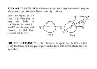
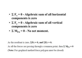
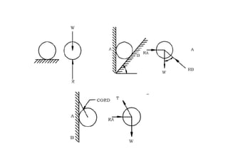
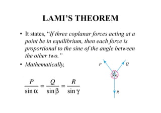
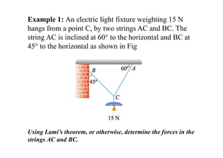
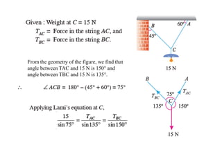
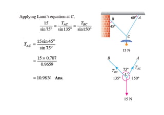
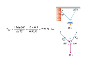
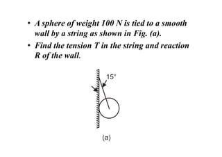
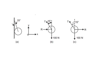
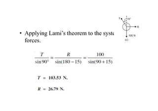
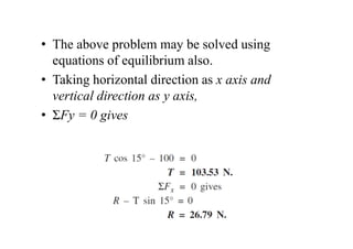
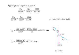
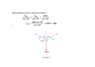
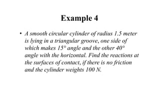
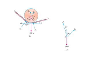
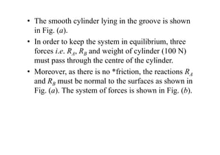
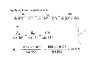
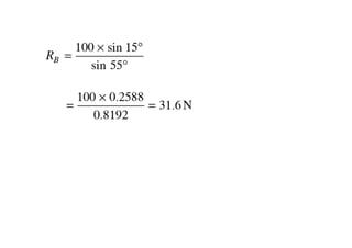
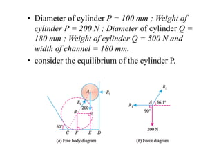
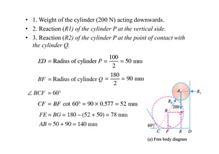
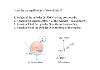
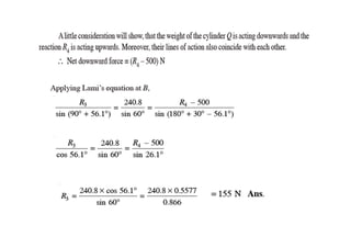
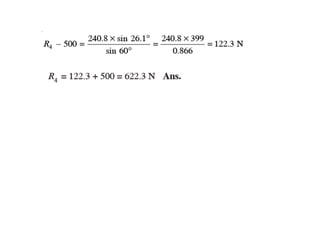
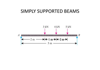
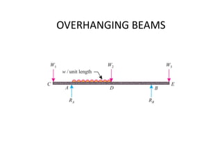
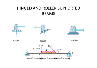
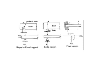
Equilibrium of
Forces
Equilibrium of Rigid Bodies
• When an external force is Engineering on a
stationery body, the body may start moving or
may start rotating about any point.
• But if the body does not start moving and also
does not start rotating about any point, then the
body is said to be in equilibrium.
• EQUILIBRIUM: Any system of forces,
which keeps the body at rest, is said to be in
equilibrium i.e. in equilibrium, the state of the
body is not affected by the action of the force
system.
• Mathematically, if the resultant of all the
forces is zero and the algebraic sum of
moments of all the forces about any coplanar
point is zero, then the body is said to be in
equilibrium.
• Σ Fx = 0 - Algebraic sum of all horizontal
components is zero
• Σ Fy = 0 - Algebraic sum of all vertical
components is zero
• Σ MFA = 0 - No net moment.
Free Body Diagram
• Free Body Diagram: Free body diagrams (FBD)
are essential in order to completely understand
and solve any Engineering mechanics problem.
• This involves isolating the body that is being
considered from all other bodies and identifying
all the forces - actions and reactions that act on
the body.
• The isolation should exist mentally and should be
represented on paper.
• Free Body Diagram (F.B.D.): If a body is
resting against support/s and if all the supports
are removed and replaced by their reactions
exerted on the body, then the body is said to be
free body.
• The sketch of free body with all active (e.g.
weight) and the reactive forces (e.g. reaction)
is called as Free Body Diagram (F. B. D.).
Forces required to be shown in F.B.D:
• 1. Weight (always acts vertically downwards
through c.g. of the body)
• 2. Support reactions.
• 3. Internal forces at cut elements e.g. tension in
cords, strings, wires, tensile / compressive
forces in bars etc.
• 4. Frictional forces.
• 5. Engineering (active) and reactive forces.
LAMI’S THEOREM
• It states, “If three coplanar forces acting at a
point be in equilibrium, then each force is
proportional to the sine of the angle between
the other two.”
• Mathematically,
Example 1: An electric light fixture weighting 15 N
hangs from a point C, by two strings AC and BC. The
string AC is inclined at 60° to the horizontal and BC at
45° to the horizontal as shown in Fig
Using Lami’s theorem, or otherwise, determine the forces in the
strings AC and BC.
From the geometry of the figure, we find that
angle between TAC and 15 N is 150° and
angle between TBC and 15 N is 135°.
• A sphere of weight 100 N is tied to a smooth
wall by a string as shown in Fig. (a).
• Find the tension T in the string and reaction
R of the wall.
• Applying Lami’s theorem to the system of
forces.
• The above problem may be solved using
equations of equilibrium also.
• Taking horizontal direction as x axis and
vertical direction as y axis,
• ΣFy = 0 gives
Example 3: A string ABCD, attached to fixed points A and D
has two equal weights of 1000 N attached to it at B and C. The
weights rest with the portions AB and CD inclined at angles as
shown in Fig
Find the tensions in the portions AB, BC and CD of the string,
if the inclination of the portion BC with the vertical is 120°.
Given : Load at B = Load at C = 1000 N
For the sake of convenience, let us split up the string ABCD into two parts. The
system of forces at joints B and is shown in Fig. (a) and (b).
Example 4
• A smooth circular cylinder of radius 1.5 meter
is lying in a triangular groove, one side of
which makes 15° angle and the other 40°
angle with the horizontal. Find the reactions at
the surfaces of contact, if there is no friction
and the cylinder weights 100 N.
• The smooth cylinder lying in the groove is shown
in Fig. (a).
• In order to keep the system in equilibrium, three
forces i.e. RA, RB and weight of cylinder (100 N)
must pass through the centre of the cylinder.
• Moreover, as there is no *friction, the reactions RA
and RB must be normal to the surfaces as shown in
Fig. (a). The system of forces is shown in Fig. (b).
• Two cylinders P and Q rest in a channel as shown
in Fig. The cylinder P has diameter of 100 mm
and weighs 200 N, whereas the cylinder Q has
diameter of 180 mm and weighs 500 N.
• If the bottom width of the box is 180 mm, with
one side vertical and the other inclined at 60°,
determine the pressures at all the four points of
contact.
• Diameter of cylinder P = 100 mm ; Weight of
cylinder P = 200 N ; Diameter of cylinder Q =
180 mm ; Weight of cylinder Q = 500 N and
width of channel = 180 mm.
• consider the equilibrium of the cylinder P.
• 1. Weight of the cylinder (200 N) acting downwards.
• 2. Reaction (R1) of the cylinder P at the vertical side.
• 3. Reaction (R2) of the cylinder P at the point of contact with
the cylinder Q.
consider the equilibrium of the cylinder P.
1. Weight of the cylinder Q (500 N) acting downwards.
2. Reaction R2 equal to 240.8 N of the cylinder P on cylinder Q.
3. Reaction R3 of the cylinder Q on the inclined surface.
4. Reaction R4 of the cylinder Q on the base of the channel.
Equilibrium of Beams
• When a number of forces act on a body, and the body
is supported on another body, then the second body
exerts a force on the first body. This force is known as
reaction on the first body at the point of contact, so
that the first body is in equilibrium.
• BEAM: It is a horizontal or inclined structural member
carrying transverse loads and supported at the ends or
anywhere throughout its length.
• SUPPORT: Arrangement on which the beam rests e.g.
wall, column etc.
• SPAN OF BEAM: Centre to centre distance two end
supports.
• Point load or Concentrated load: It is the load acting at a particular
point or the load is concentrated at a particular point (Refer fig.1)
• Uniformly Distributed Load (UDL): If the load is distributed on the
beam such that the load per unit length is constant, then it is
known as Uniformly Distributed Load (udl). (Refer fig.2a)
• It is expressed as w/unit length, where, ‘w’ is the intensity of udl
• e.g. 2 N/m, 10 kN/m etc.
• The udl can be converted into its equivalent point load, having
magnitude ‘w.l’ (intensity of udl x span of udl). This point load will
act at the mid-point of the beam over which it is acting. (Refer
fig.2b)
• Uniformly Varying Load (UVL): If the load is spread over a
beam, varying uniformly on each length
(increasing/decreasing), it is known as Uniformly Varying
Load (uvl). is constant. (Refer fig.3)
• Sometimes the load varies from zero at one end to ‘w’ at
other end, then it is known as triangular load. Triangular
load can be converted into its equivalent point load having
magnitude ‘ wl/2’ ( = area of the triangle) and acts at the
centre of distribution i.e. at a distance 2l/3 from point A or
at a distance l/3 from point B.
• Non-uniformly Distributed Load: The load distribution on
the beam is such that the load per unit length is not
constant. (Refer fig.4)
• SUPPORT REACTION: To keep the beam in
equilibrium under the action of Engineering
forces (loads), the support develops the
reactive forces to nullify the effect of
Engineering forces. These reactive forces are
known as “Support Reactions”.
SIMPLY SUPPORTED BEAMS
OVERHANGING BEAMS
HINGED AND ROLLER SUPPORTED
BEAMS
ROLLER ROLLER HINGED
A simply supported beam, AB of span 6
m is loaded as shown in Fig
Determine the reactions R A and R B of the beam
Engineering Mechanics- Equilibrium of forces

Engineering Mechanics- Equilibrium of forces

  • 1.
  • 2.
    Equilibrium of RigidBodies • When an external force is Engineering on a stationery body, the body may start moving or may start rotating about any point. • But if the body does not start moving and also does not start rotating about any point, then the body is said to be in equilibrium.
  • 3.
    • EQUILIBRIUM: Anysystem of forces, which keeps the body at rest, is said to be in equilibrium i.e. in equilibrium, the state of the body is not affected by the action of the force system. • Mathematically, if the resultant of all the forces is zero and the algebraic sum of moments of all the forces about any coplanar point is zero, then the body is said to be in equilibrium.
  • 5.
    • Σ Fx= 0 - Algebraic sum of all horizontal components is zero • Σ Fy = 0 - Algebraic sum of all vertical components is zero • Σ MFA = 0 - No net moment.
  • 6.
    Free Body Diagram •Free Body Diagram: Free body diagrams (FBD) are essential in order to completely understand and solve any Engineering mechanics problem. • This involves isolating the body that is being considered from all other bodies and identifying all the forces - actions and reactions that act on the body. • The isolation should exist mentally and should be represented on paper.
  • 7.
    • Free BodyDiagram (F.B.D.): If a body is resting against support/s and if all the supports are removed and replaced by their reactions exerted on the body, then the body is said to be free body. • The sketch of free body with all active (e.g. weight) and the reactive forces (e.g. reaction) is called as Free Body Diagram (F. B. D.).
  • 8.
    Forces required tobe shown in F.B.D: • 1. Weight (always acts vertically downwards through c.g. of the body) • 2. Support reactions. • 3. Internal forces at cut elements e.g. tension in cords, strings, wires, tensile / compressive forces in bars etc. • 4. Frictional forces. • 5. Engineering (active) and reactive forces.
  • 11.
    LAMI’S THEOREM • Itstates, “If three coplanar forces acting at a point be in equilibrium, then each force is proportional to the sine of the angle between the other two.” • Mathematically,
  • 12.
    Example 1: Anelectric light fixture weighting 15 N hangs from a point C, by two strings AC and BC. The string AC is inclined at 60° to the horizontal and BC at 45° to the horizontal as shown in Fig Using Lami’s theorem, or otherwise, determine the forces in the strings AC and BC.
  • 13.
    From the geometryof the figure, we find that angle between TAC and 15 N is 150° and angle between TBC and 15 N is 135°.
  • 16.
    • A sphereof weight 100 N is tied to a smooth wall by a string as shown in Fig. (a). • Find the tension T in the string and reaction R of the wall.
  • 18.
    • Applying Lami’stheorem to the system of forces.
  • 19.
    • The aboveproblem may be solved using equations of equilibrium also. • Taking horizontal direction as x axis and vertical direction as y axis, • ΣFy = 0 gives
  • 20.
    Example 3: Astring ABCD, attached to fixed points A and D has two equal weights of 1000 N attached to it at B and C. The weights rest with the portions AB and CD inclined at angles as shown in Fig Find the tensions in the portions AB, BC and CD of the string, if the inclination of the portion BC with the vertical is 120°.
  • 21.
    Given : Loadat B = Load at C = 1000 N For the sake of convenience, let us split up the string ABCD into two parts. The system of forces at joints B and is shown in Fig. (a) and (b).
  • 24.
    Example 4 • Asmooth circular cylinder of radius 1.5 meter is lying in a triangular groove, one side of which makes 15° angle and the other 40° angle with the horizontal. Find the reactions at the surfaces of contact, if there is no friction and the cylinder weights 100 N.
  • 26.
    • The smoothcylinder lying in the groove is shown in Fig. (a). • In order to keep the system in equilibrium, three forces i.e. RA, RB and weight of cylinder (100 N) must pass through the centre of the cylinder. • Moreover, as there is no *friction, the reactions RA and RB must be normal to the surfaces as shown in Fig. (a). The system of forces is shown in Fig. (b).
  • 29.
    • Two cylindersP and Q rest in a channel as shown in Fig. The cylinder P has diameter of 100 mm and weighs 200 N, whereas the cylinder Q has diameter of 180 mm and weighs 500 N. • If the bottom width of the box is 180 mm, with one side vertical and the other inclined at 60°, determine the pressures at all the four points of contact.
  • 30.
    • Diameter ofcylinder P = 100 mm ; Weight of cylinder P = 200 N ; Diameter of cylinder Q = 180 mm ; Weight of cylinder Q = 500 N and width of channel = 180 mm. • consider the equilibrium of the cylinder P.
  • 31.
    • 1. Weightof the cylinder (200 N) acting downwards. • 2. Reaction (R1) of the cylinder P at the vertical side. • 3. Reaction (R2) of the cylinder P at the point of contact with the cylinder Q.
  • 33.
    consider the equilibriumof the cylinder P. 1. Weight of the cylinder Q (500 N) acting downwards. 2. Reaction R2 equal to 240.8 N of the cylinder P on cylinder Q. 3. Reaction R3 of the cylinder Q on the inclined surface. 4. Reaction R4 of the cylinder Q on the base of the channel.
  • 36.
    Equilibrium of Beams •When a number of forces act on a body, and the body is supported on another body, then the second body exerts a force on the first body. This force is known as reaction on the first body at the point of contact, so that the first body is in equilibrium. • BEAM: It is a horizontal or inclined structural member carrying transverse loads and supported at the ends or anywhere throughout its length. • SUPPORT: Arrangement on which the beam rests e.g. wall, column etc. • SPAN OF BEAM: Centre to centre distance two end supports.
  • 37.
    • Point loador Concentrated load: It is the load acting at a particular point or the load is concentrated at a particular point (Refer fig.1) • Uniformly Distributed Load (UDL): If the load is distributed on the beam such that the load per unit length is constant, then it is known as Uniformly Distributed Load (udl). (Refer fig.2a) • It is expressed as w/unit length, where, ‘w’ is the intensity of udl • e.g. 2 N/m, 10 kN/m etc. • The udl can be converted into its equivalent point load, having magnitude ‘w.l’ (intensity of udl x span of udl). This point load will act at the mid-point of the beam over which it is acting. (Refer fig.2b)
  • 38.
    • Uniformly VaryingLoad (UVL): If the load is spread over a beam, varying uniformly on each length (increasing/decreasing), it is known as Uniformly Varying Load (uvl). is constant. (Refer fig.3) • Sometimes the load varies from zero at one end to ‘w’ at other end, then it is known as triangular load. Triangular load can be converted into its equivalent point load having magnitude ‘ wl/2’ ( = area of the triangle) and acts at the centre of distribution i.e. at a distance 2l/3 from point A or at a distance l/3 from point B. • Non-uniformly Distributed Load: The load distribution on the beam is such that the load per unit length is not constant. (Refer fig.4)
  • 39.
    • SUPPORT REACTION:To keep the beam in equilibrium under the action of Engineering forces (loads), the support develops the reactive forces to nullify the effect of Engineering forces. These reactive forces are known as “Support Reactions”.
  • 40.
  • 41.
  • 42.
    HINGED AND ROLLERSUPPORTED BEAMS ROLLER ROLLER HINGED
  • 44.
    A simply supportedbeam, AB of span 6 m is loaded as shown in Fig Determine the reactions R A and R B of the beam