Downloaded 79 times


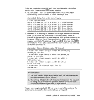
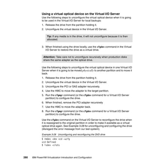
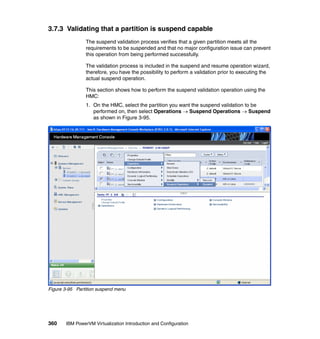
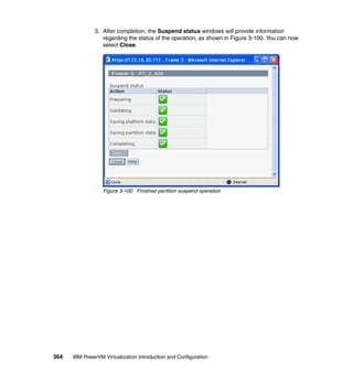
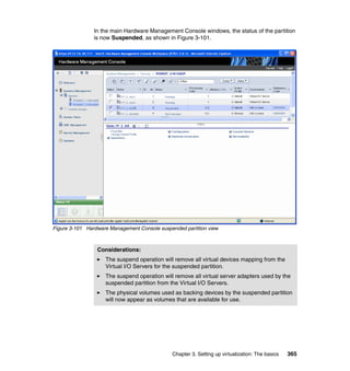
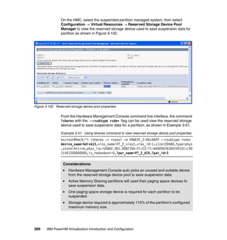
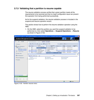
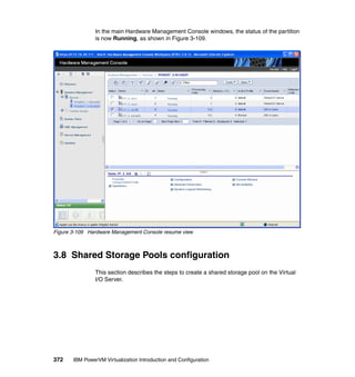
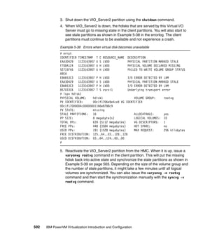
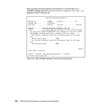
![202 IBM PowerVM Virtualization Introduction and Configuration
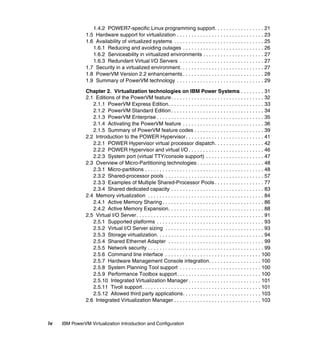
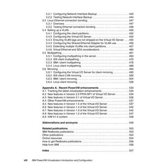
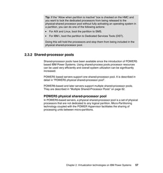
2.14.4 SMT control in Linux
SMT can be enabled or disabled at boot time or dynamically after the partition is
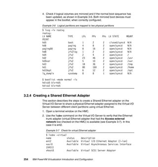
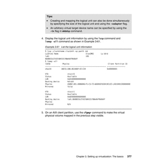
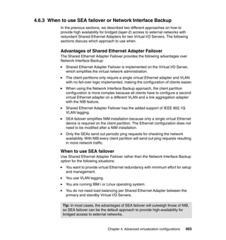
running.
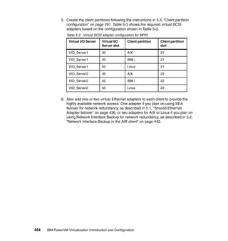
Controlling SMT at boot time
After the next operating system reboot is performed, to enable or disable SMT at
boot, use the following boot option at the boot prompt:
boot: linux smt-enabled=on
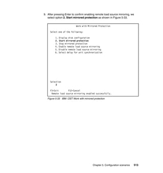
Change the on to off to disable SMT at boot time. The default is SMT on. On a
POWER5 or POWER6 based server SMT-2 will be enabled on a POWER7
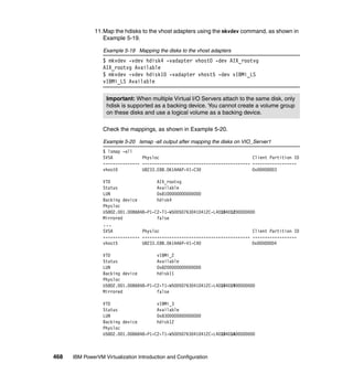
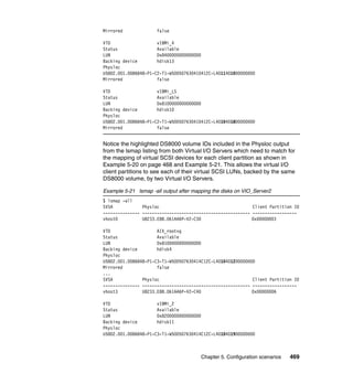
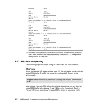
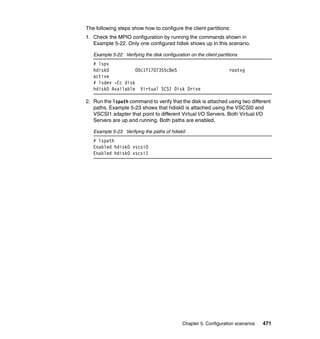
server with a POWER7 enabled kernel SMT-4 will be enabled.
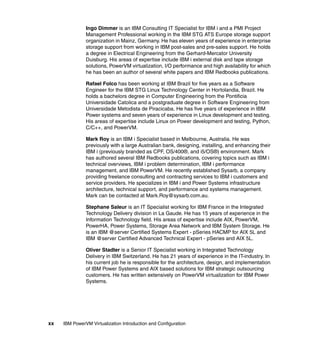
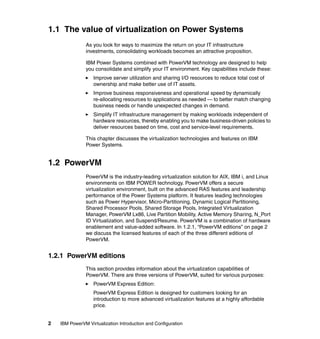
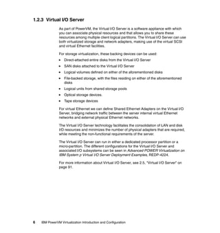
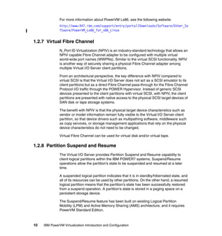
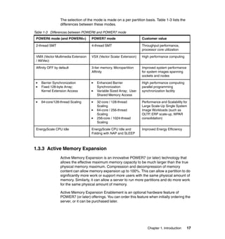
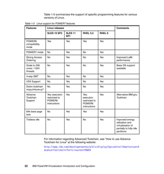
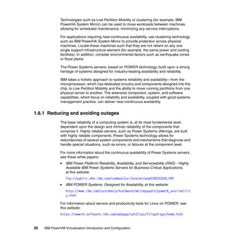
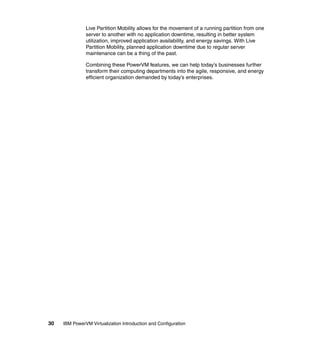
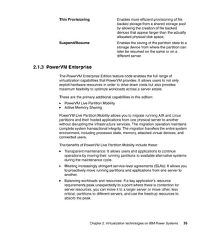
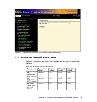
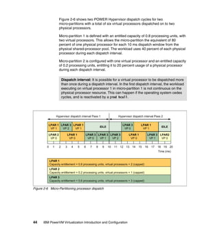
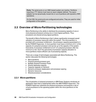
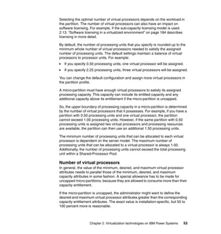
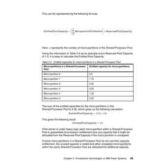
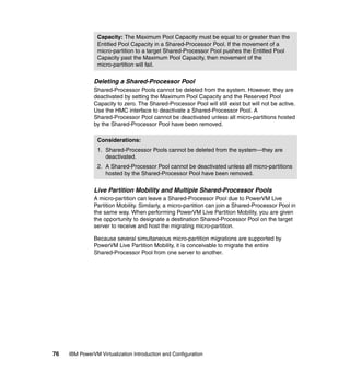
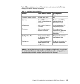
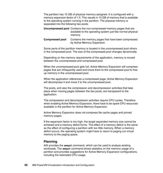
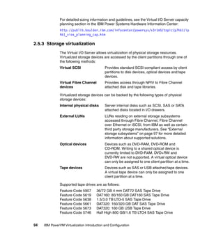
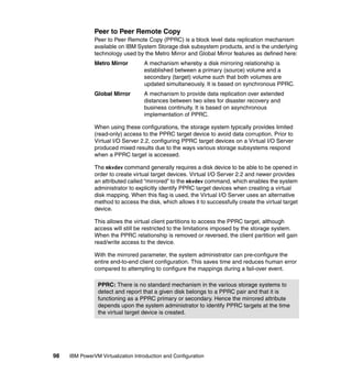
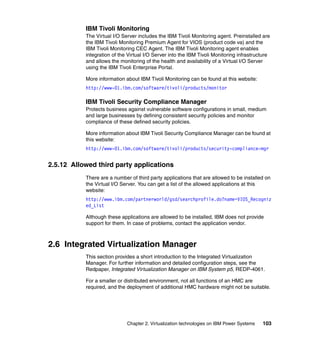
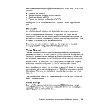
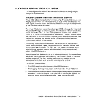
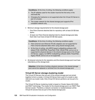
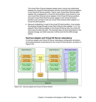
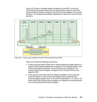
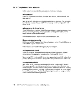
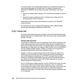
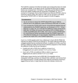
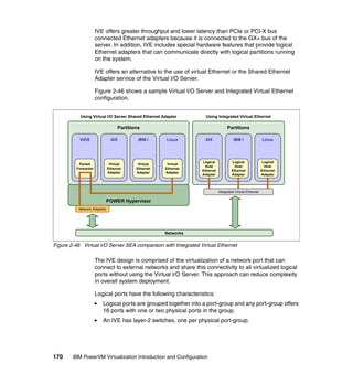
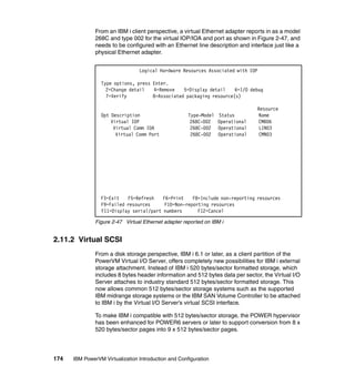
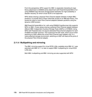
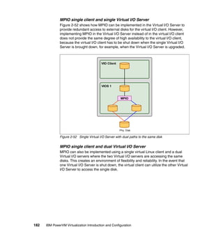
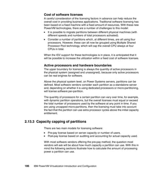
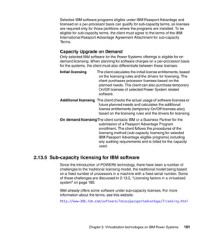
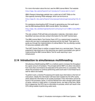
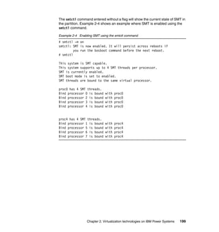
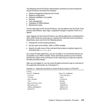
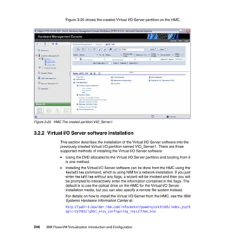
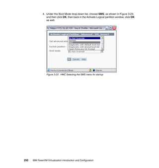
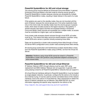
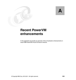
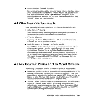
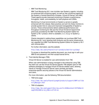
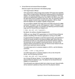
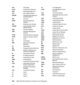
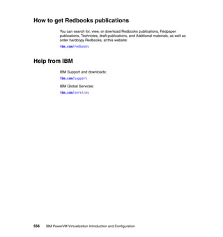
Controlling SMT using the ppc64_cpu command
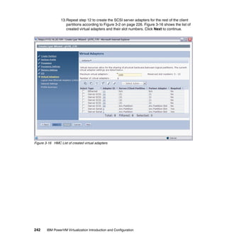
When Linux is up and running SMT can be controlled using the ppc64_cpu
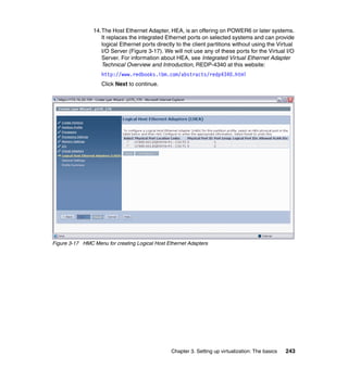
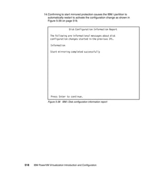
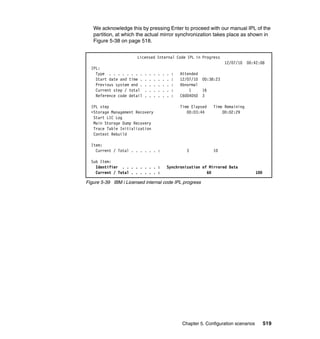
command. Example 2-5 shows an example of how SMT can be turned on
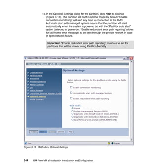
dynamically. After SMT has been enabled, Linux sees two processors in
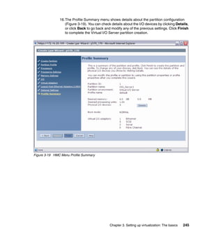
/proc/cpuinfo. In the example, Red Hat 5.6 was used, which does not yet support
POWER7. Therefore the processors appear as POWER6 and only two threads
are available.
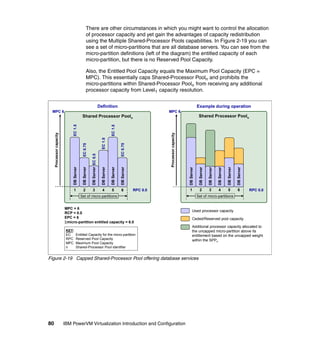
Example 2-5 Using ppc64_cpu to control SMT on Linux
[root@P7-1-RHEL ~]# ppc64_cpu --smt
SMT is off
[root@P7-1-RHEL ~]# ppc64_cpu --smt=on
[root@P7-1-RHEL ~]# ppc64_cpu --smt
SMT is on
[root@P7-1-RHEL ~]# cat /proc/cpuinfo
processor : 0
cpu : POWER6 (architected), altivec supported
clock : 3000.000000MHz
revision : 2.1 (pvr 003f 0201)
processor : 1
cpu : POWER6 (architected), altivec supported
clock : 3000.000000MHz
revision : 2.1 (pvr 003f 0201)
timebase : 512000000
platform : pSeries
machine : CHRP IBM,8233-E8B
[root@P7-1-RHEL ~]#](https://image.slidesharecdn.com/sg247940-130416014807-phpapp02/85/IBM-PowerVM-Virtualization-Introduction-and-Configuration-230-320.jpg)


![222 IBM PowerVM Virtualization Introduction and Configuration
chvopt Shell Commands
loadopt awk
lsrep cat
lsvopt chmod
mkrep clear
mkvopt cp
rmrep crontab
rmvopt date
unloadopt ftp
grep
head
ls
man
mkdir
more
mv
rm
sed
stty
tail
tee
vi
wall
wc
who
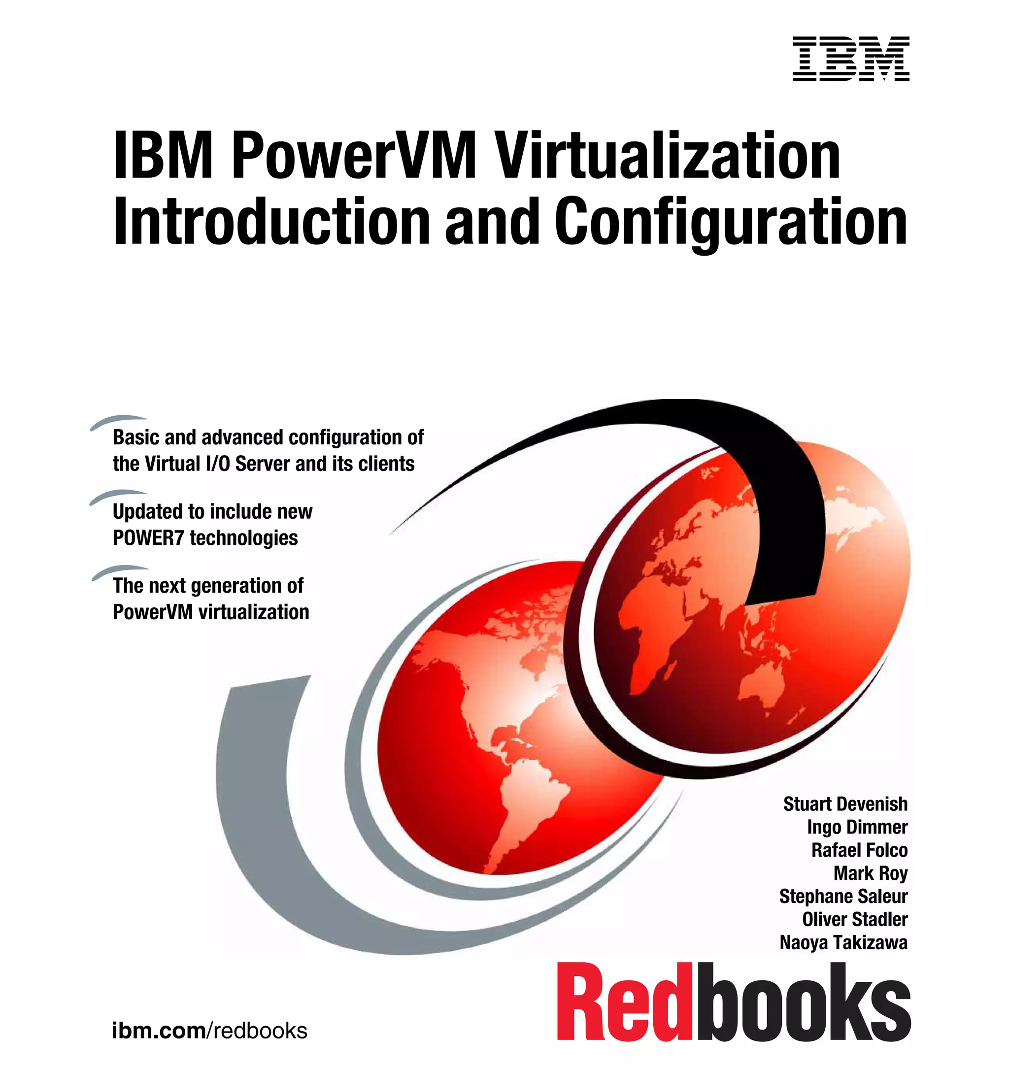
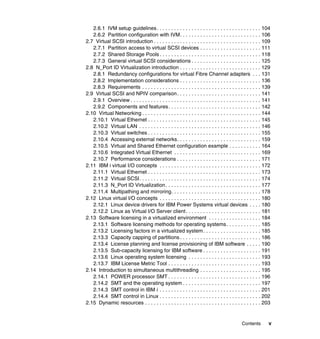
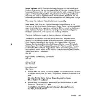
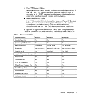
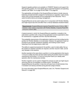
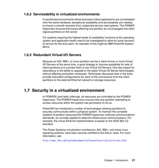
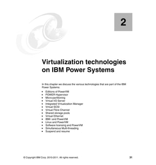
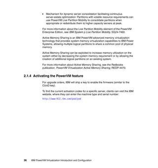
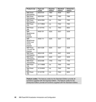
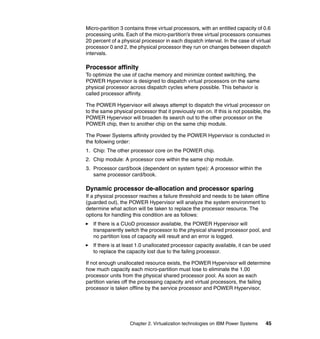
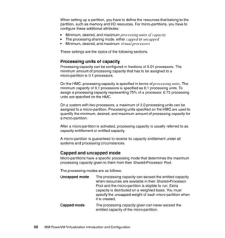
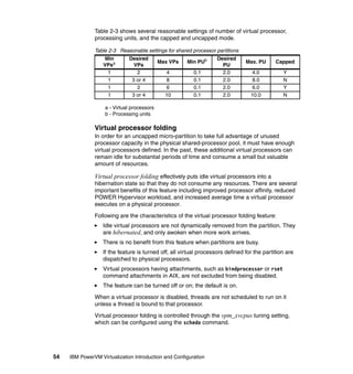
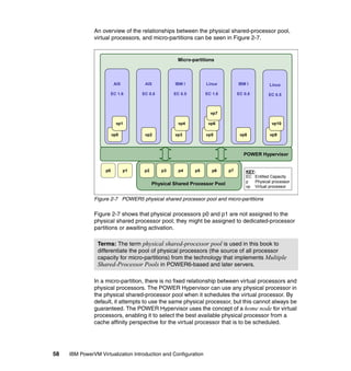
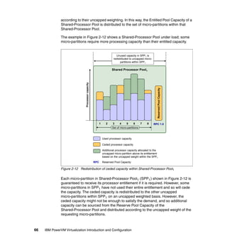
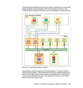
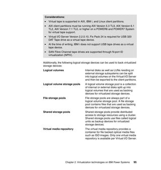
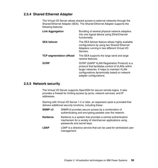
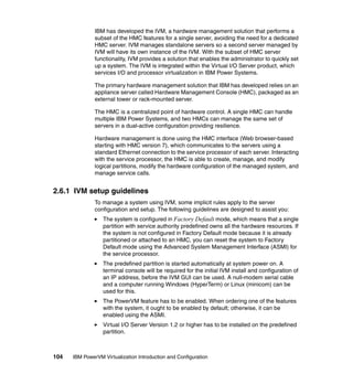
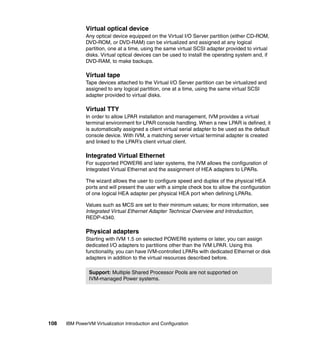
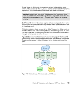
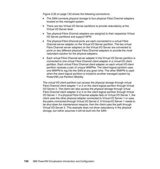
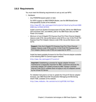
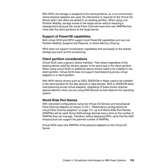
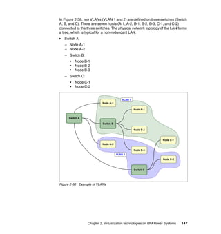
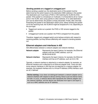
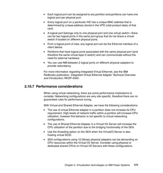
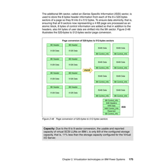
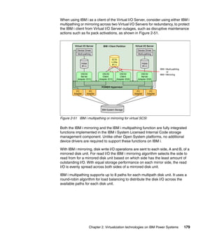
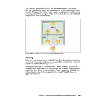
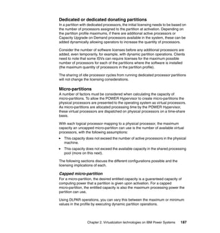
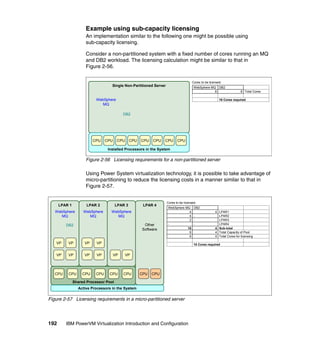
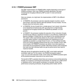
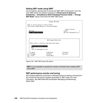
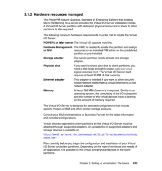
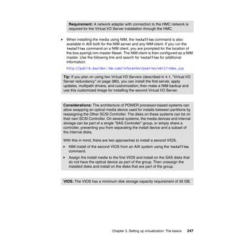
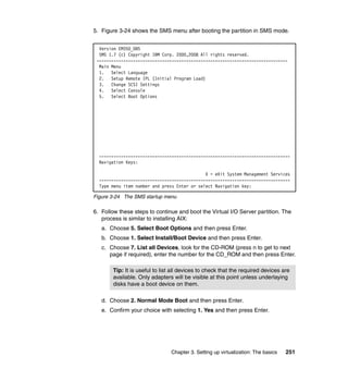
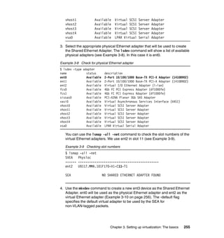
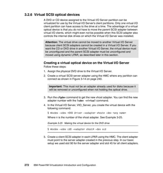
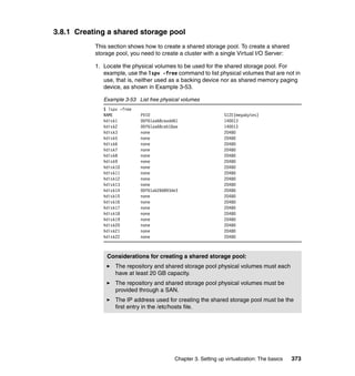
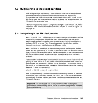
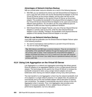
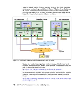
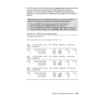
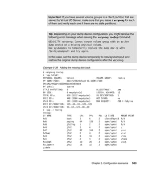
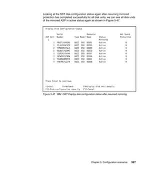
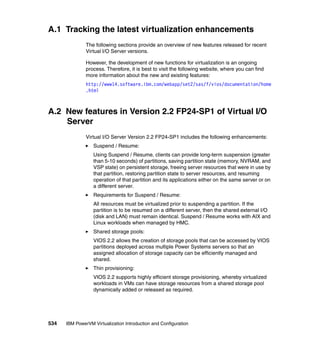
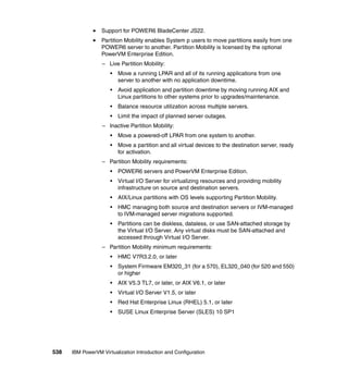
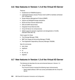
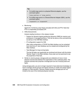
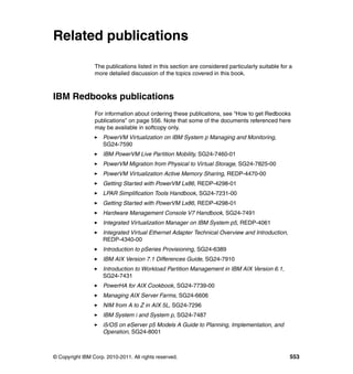
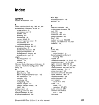
To receive further help about these commands, use the help command, as
shown in Example 3-2.
Example 3-2 Help command
$ help errlog
Usage: errlog [[ -ls][-seq Sequence_number] | -rm Days]]
Displays or clears the error log.
-ls Displays information about errors in the error log file
in a detailed format.
-seq Displays information about a specific error in the error log file
by the sequence number.
-rm Deletes all entries from the error log older than the
number of days specified by the Days parameter.](https://image.slidesharecdn.com/sg247940-130416014807-phpapp02/85/IBM-PowerVM-Virtualization-Introduction-and-Configuration-250-320.jpg)
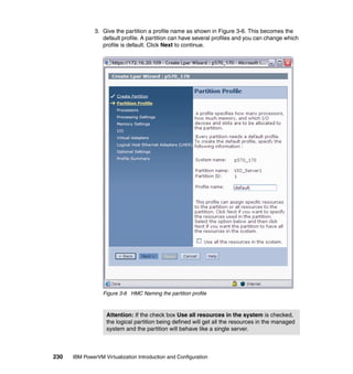
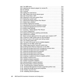
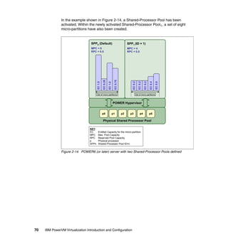
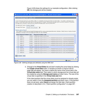
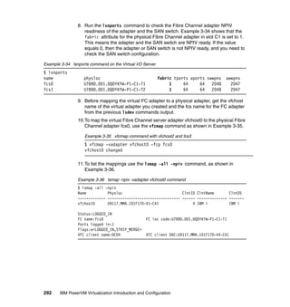
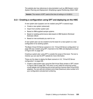
![Chapter 3. Setting up virtualization: The basics 257
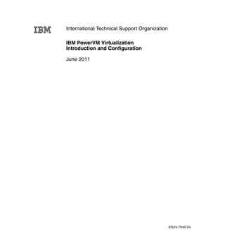
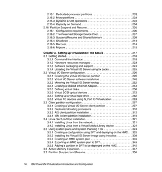
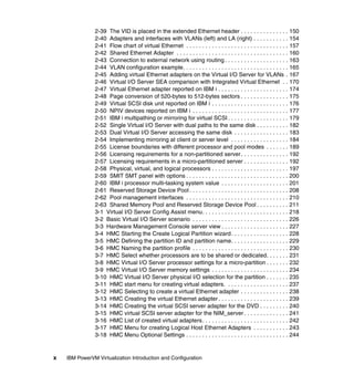
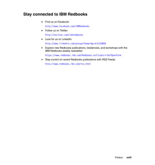
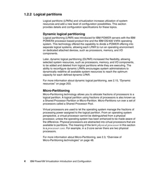
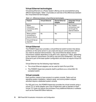
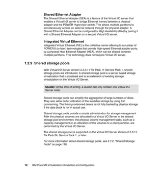
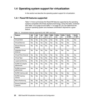
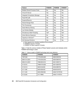
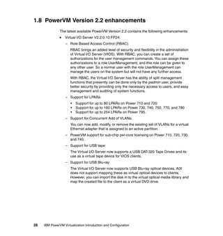
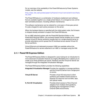
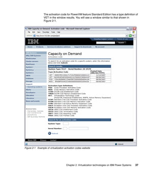
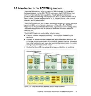
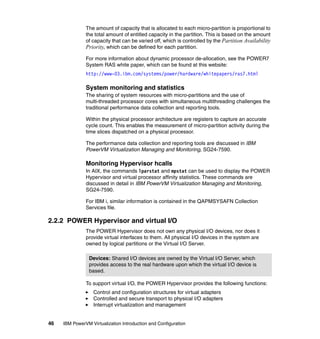
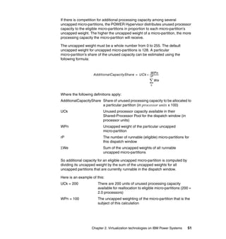
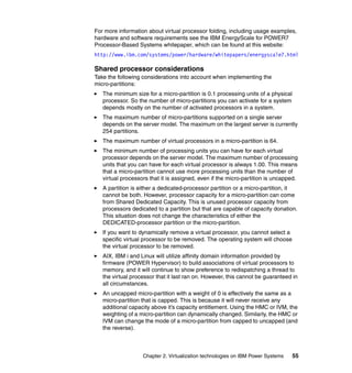
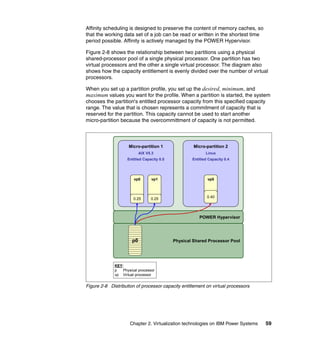
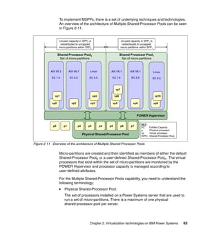
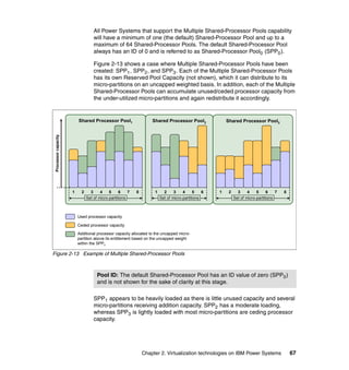
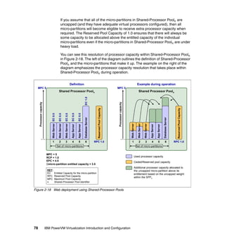
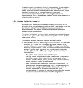
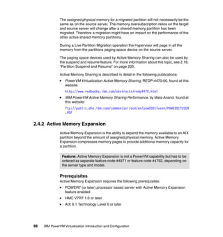
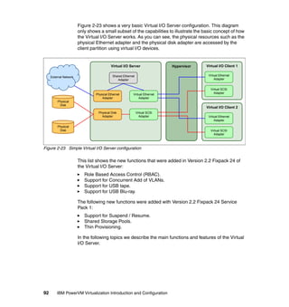
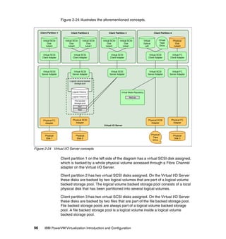
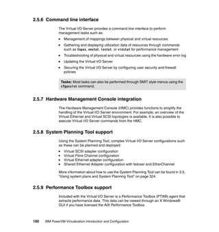
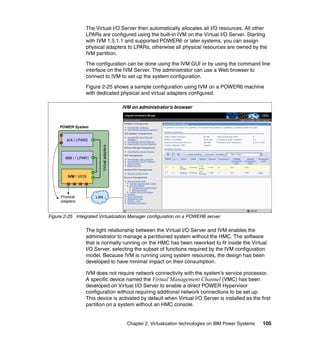
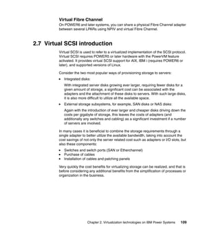
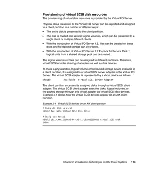
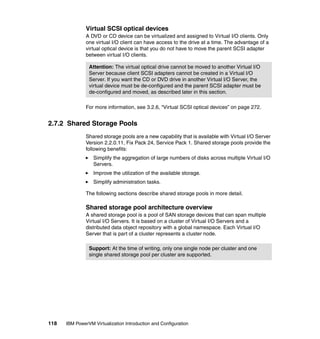
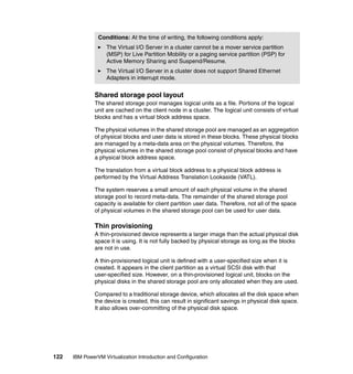
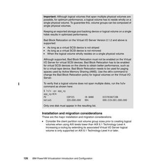
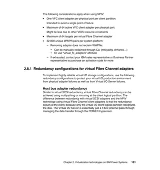
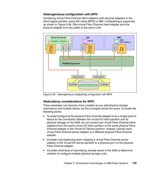
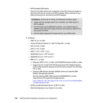
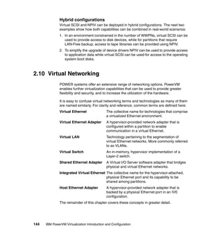
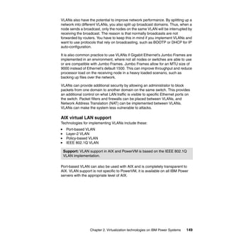
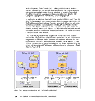
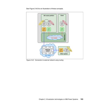
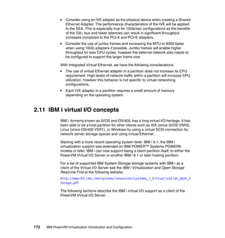
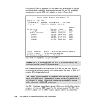
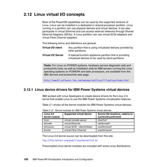
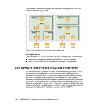
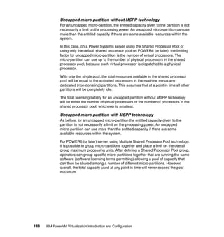
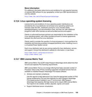
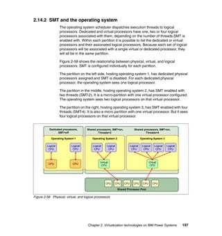
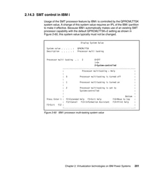
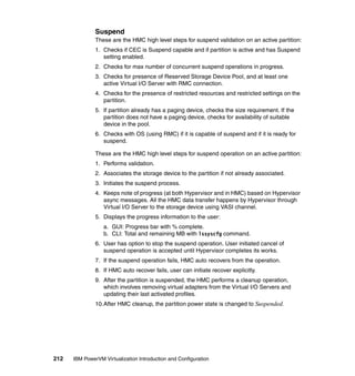
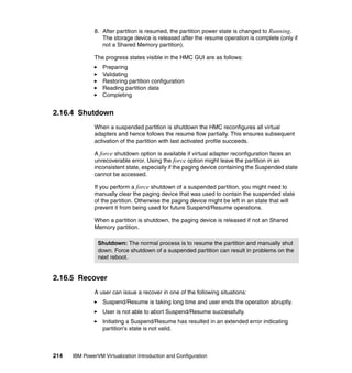
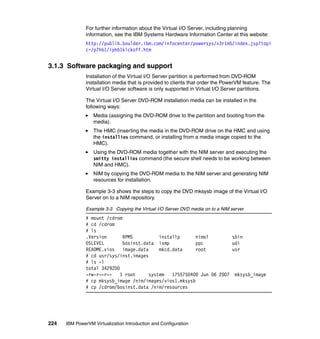
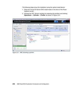
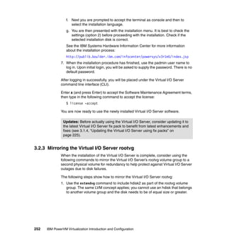
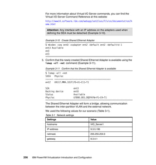
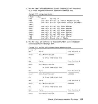
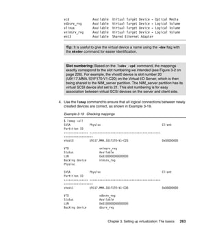
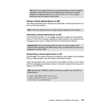
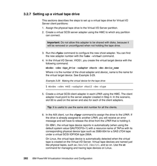
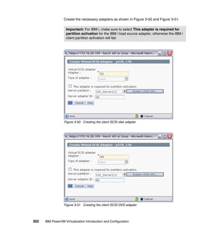
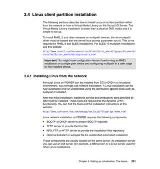
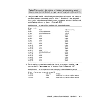
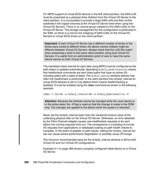
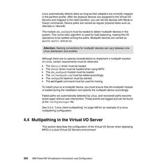
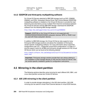
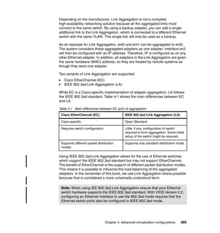
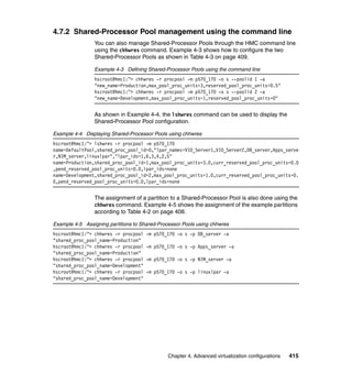
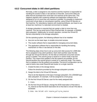
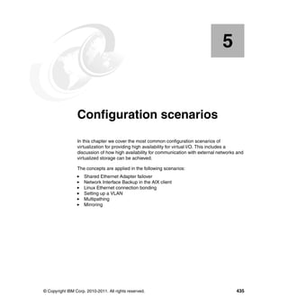
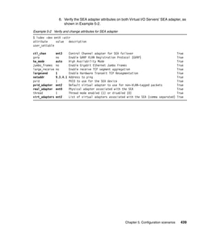
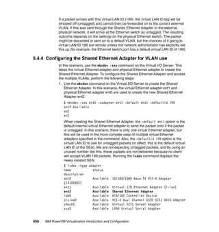
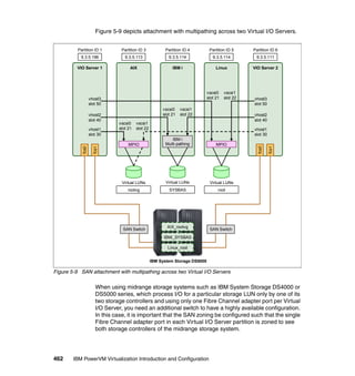
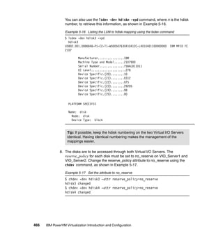
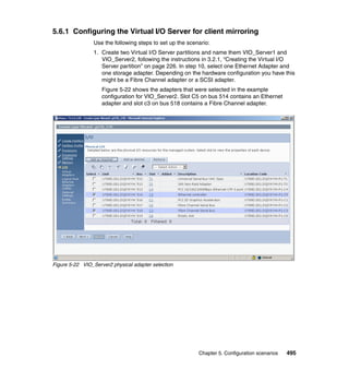
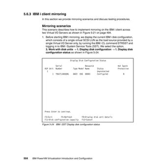
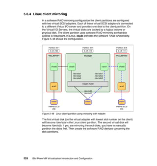
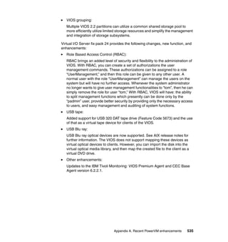
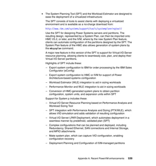
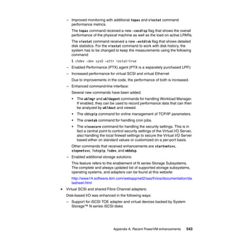
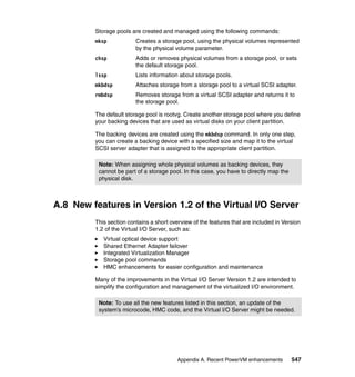
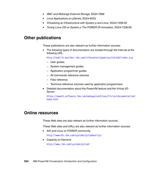
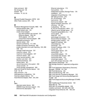
6. Use the cfgassist command (see Figure 3-25) or the mktcpip command
(see Example 3-12) to configure the interface on the SEA, ent3.
Figure 3-25 Setting TCP/IP parameters using the cfgassist command
Example 3-12 Defining IP settings on the created SEA
$ mktcpip -hostname VIO_Server1 -inetaddr 9.3.5.196 -interface en3
-netmask 255.255.254.0 -gateway 9.3.4.1
VIOS TCP/IP Configuration
Type or select values in entry fields.
Press Enter AFTER making all desired changes.
[Entry Fields]
* Hostname [VIO_Server1]
* Internet ADDRESS (dotted decimal) [9.3.5.196]
Network MASK (dotted decimal) [255.255.254.0]
* Network INTERFACE en3
Default Gateway (dotted decimal) [9.3.4.1]
NAMESERVER
Internet ADDRESS (dotted decimal) [9.3.4.2]
DOMAIN Name [itsc.austin.ibm.com]
CableType bnc +
F1=Help F2=Refresh F3=Cancel F4=List
F5=Reset F6=Command F7=Edit F8=Image
F9=Shell F10=Exit Enter=Do
Tip: There is no performance penalty for adding the IP address to the SEA
interface instead of keeping it on a separate virtual Ethernet adapter.
However, the SEA can be redefined without having to detach the interface
when the interface is kept on a separate virtual Ethernet adapter. This
provides increased serviceability.](https://image.slidesharecdn.com/sg247940-130416014807-phpapp02/85/IBM-PowerVM-Virtualization-Introduction-and-Configuration-285-320.jpg)
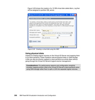
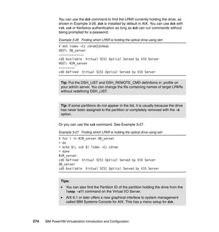

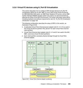
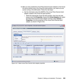
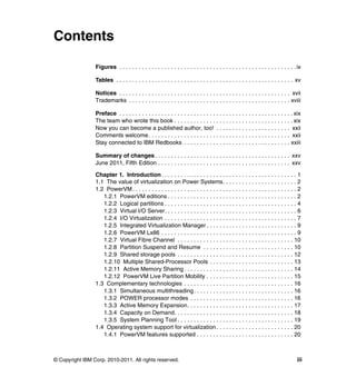
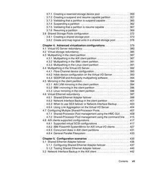
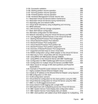
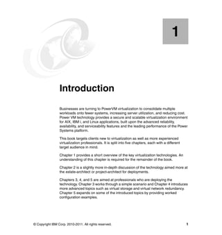
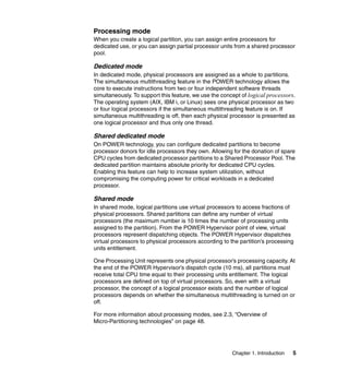
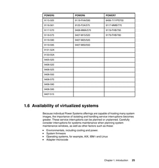
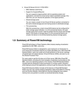
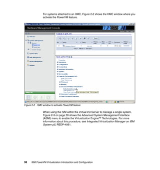
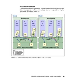
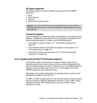
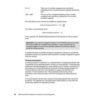
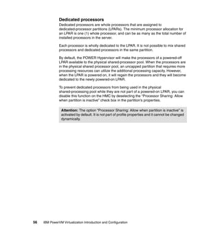
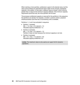
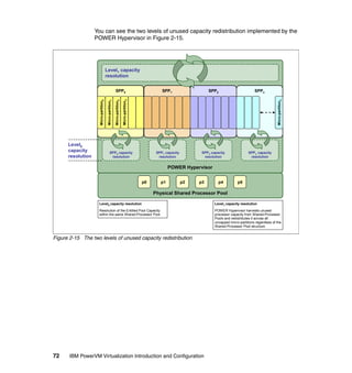
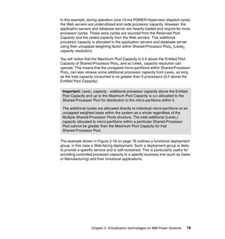
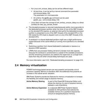
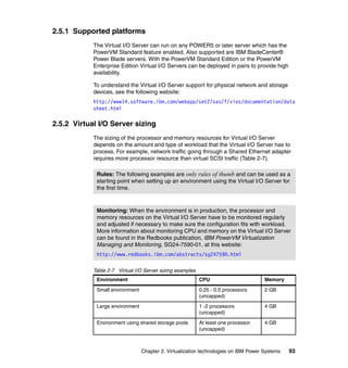
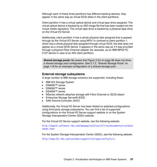
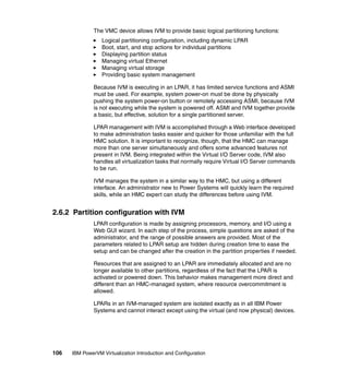
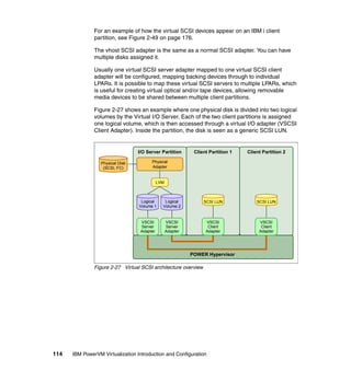
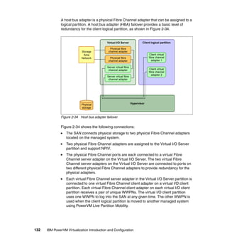
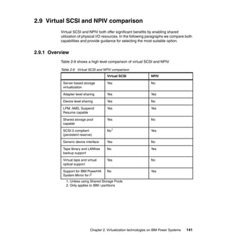
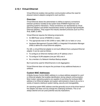
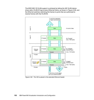
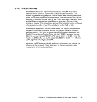
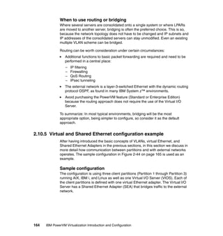
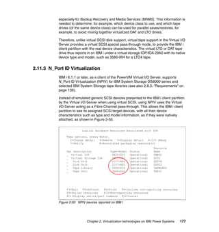
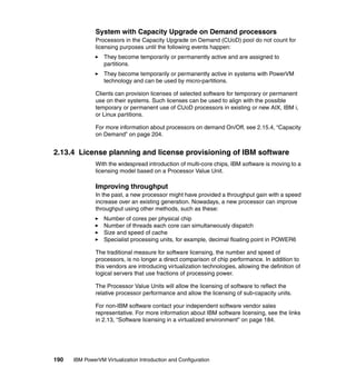
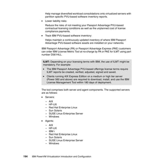
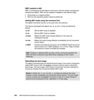
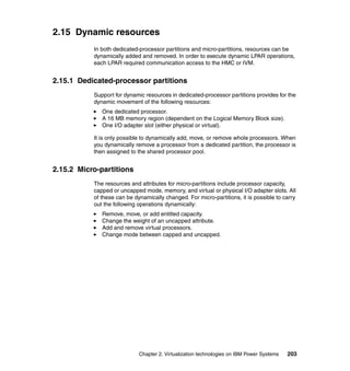
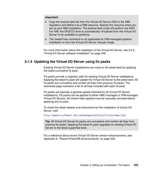
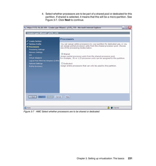
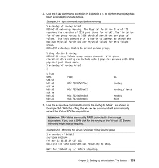
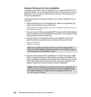
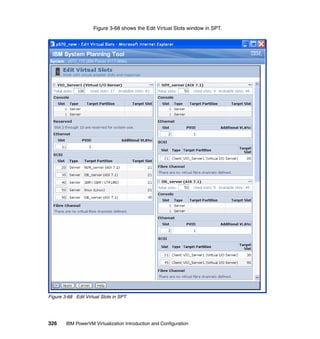
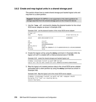
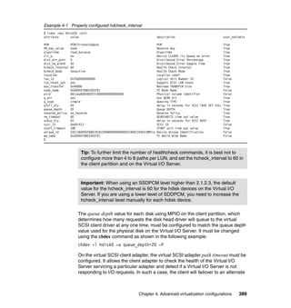
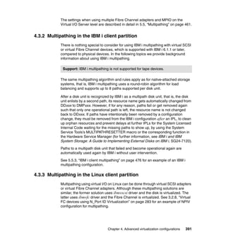
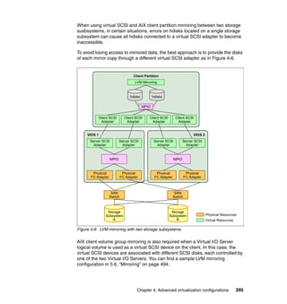
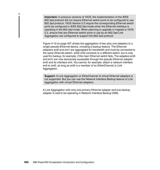
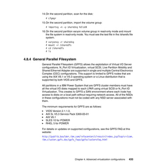
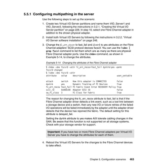
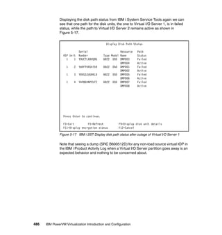
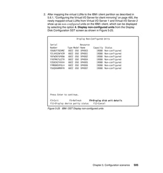
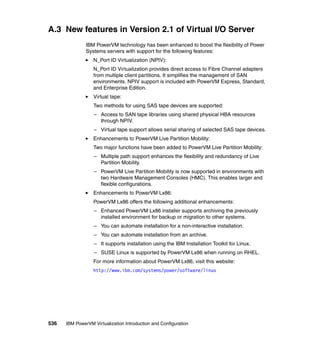
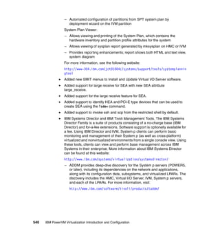
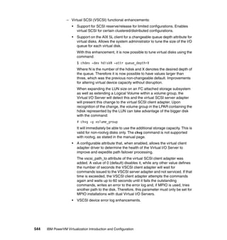
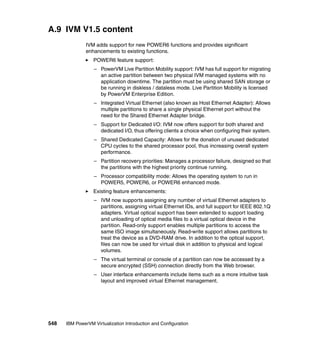
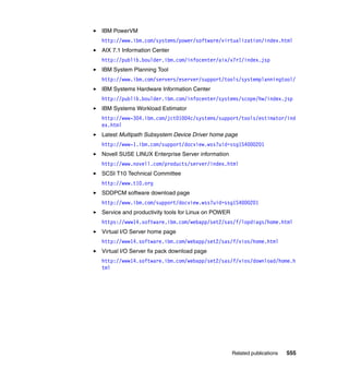
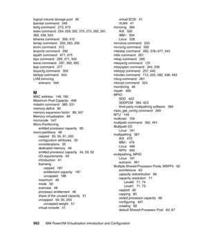
![296 IBM PowerVM Virtualization Introduction and Configuration
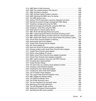
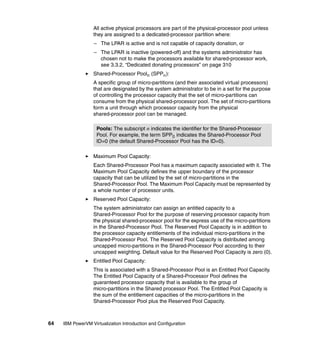
hdisk0 Available Virtual SCSI Disk Drive
hdisk1 Available 31-T1-01 IBM MPIO FC 2107
hdisk2 Available 31-T1-01 IBM MPIO FC 2107
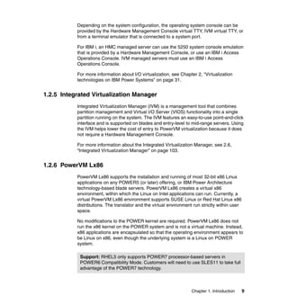
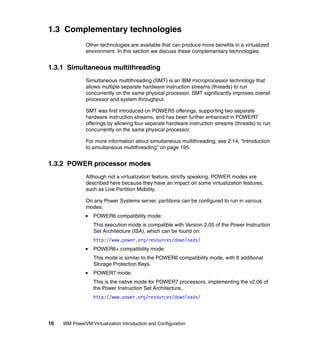
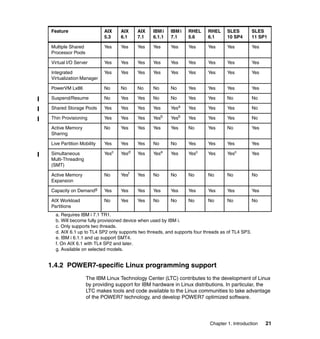
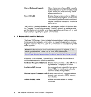
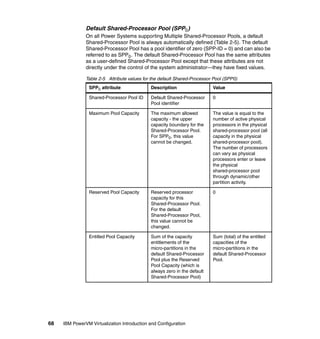
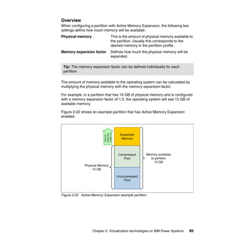
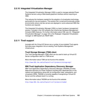
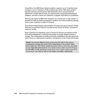
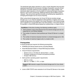
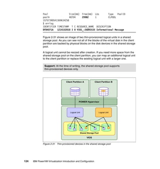
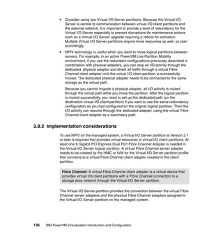
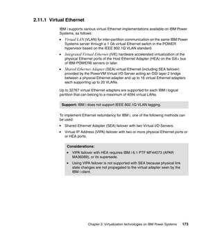
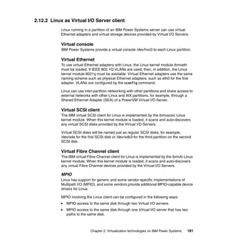
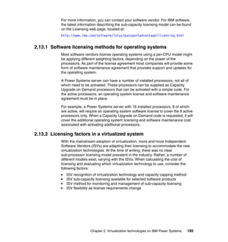
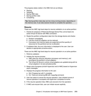
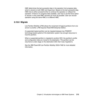
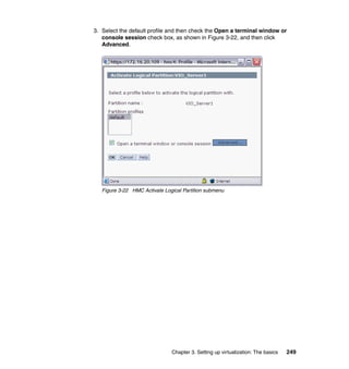
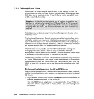
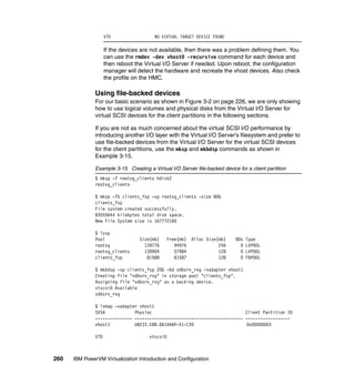
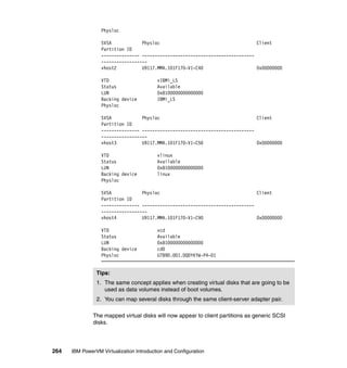
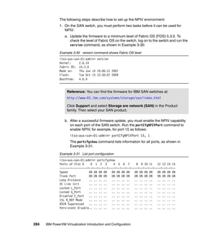
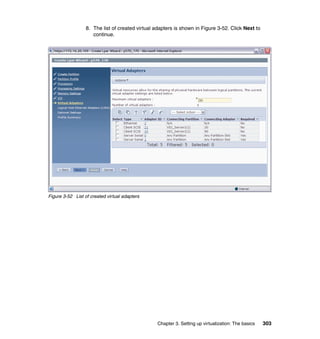
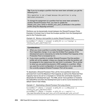
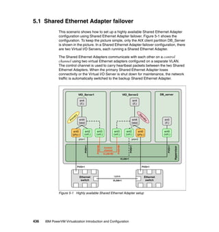
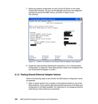
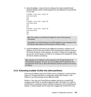
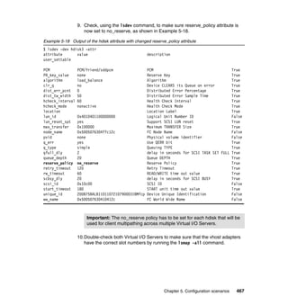
Figure 3-45 IBM i logical hardware resources with NPIV devices
From the Linux client perspective, virtual Fibre Channel has to look like a
native/physical Fibre Channel device. There is no special requirement or
configuration needed to set up a N_Port ID Virtualization (NPIV) on Linux.
After the ibmvfc driver is loaded and a virtual Fibre Channel Adapter is mapped
to a physical Fibre Channel adapter on the Virtual I/O Server, the Fibre Channel
port automatically shows up on the Linux partition. You can check if the ibmvfc
driver is loaded on the system with the lsmod command.
[root@Power7-2-RHEL ~]# lsmod |grep ibmvfc
ibmvfc 98929 4
scsi_transport_fc 84177 1 ibmvfc
scsi_mod 245569 6
scsi_dh,sg,ibmvfc,scsi_transport_fc,ibmvscsic,sd_mod
Logical Hardware Resources Associated with IOP
Type options, press Enter.
2=Change detail 4=Remove 5=Display detail 6=I/O debug
7=Verify 8=Associated packaging resource(s)
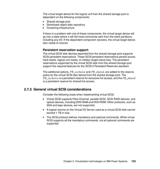
Resource
Opt Description Type-Model Status Name
Virtual IOP 6B25-001 Operational CMB07
Virtual Storage IOA 6B25-001 Operational DC04
Disk Unit 2107-A02 Operational DD005
Disk Unit 2107-A02 Operational DD006
Disk Unit 2107-A02 Operational DD007
Disk Unit 2107-A02 Operational DD008
F3=Exit F5=Refresh F6=Print F8=Include non-reporting resources
F9=Failed resources F10=Non-reporting resources
F11=Display serial/part numbers F12=Cancel](https://image.slidesharecdn.com/sg247940-130416014807-phpapp02/85/IBM-PowerVM-Virtualization-Introduction-and-Configuration-324-320.jpg)
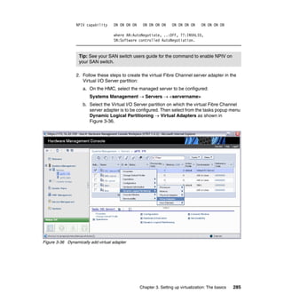
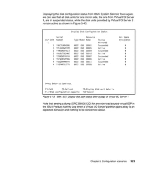
![Chapter 3. Setting up virtualization: The basics 297
You can also check the devices on the kernel log at the /var/log/messages file or
by using the dmesg command output.
[root@Power7-2-RHEL ~]# dmesg |grep vfc
ibmvfc: IBM Virtual Fibre Channel Driver version: 1.0.6 (May 28, 2009)
vio_register_driver: driver ibmvfc registering
ibmvfc 30000038: Partner initialization complete
ibmvfc 30000038: Host partition: P7_2_vios1, device: vfchost0
U5802.001.0087356-P1-C2-T1 U8233.E8B.061AB2P-V1-C56 max sectors 2048
ibmvfc 30000039: Partner initialization complete
ibmvfc 30000039: Host partition: P7_2_vios2, device: vfchost0
U5802.001.0087356-P1-C3-T1 U8233.E8B.061AB2P-V2-C57 max sectors 2048
To list the virtual Fibre Channel device, use the command lsscsi, as shown in
this example:
[root@Power7-2-RHEL ~]# lsscsi -H -v |grep fc
[5] ibmvfc
[6] ibmvfc
You can perform NPIV tracing on Linux through the filesystem attributes located
at the /sys/class directories. The files containing the devices’ attributes are useful
for checking detailed information about the virtual device and also can be used
for troubleshooting as well. These attributes files can be accessed at the
following directories:
/sys/class/fc_host/
/sys/class/fc_remote_port/
/sys/class/scsi_host/
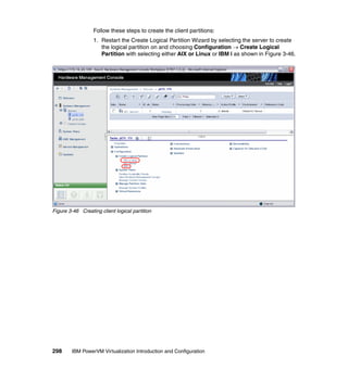
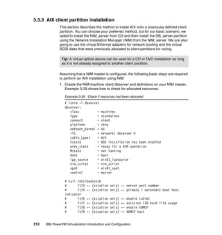
3.3 Client partition configuration
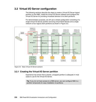
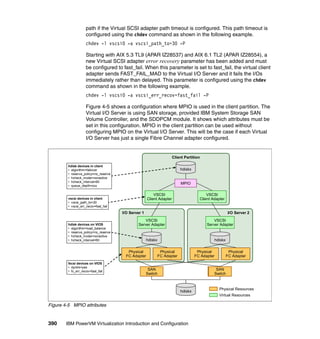
This section shows you how to create and install the four client partitions for our
basic Virtual I/O scenario shown in Figure 3-2 on page 226.
3.3.1 Creating a Virtual I/O Server client partition
The client partition definitions are similar to the creation of our Virtual I/O Server
partition, but instead of selecting VIO Server, choose AIX or Linux, or IBM i.](https://image.slidesharecdn.com/sg247940-130416014807-phpapp02/85/IBM-PowerVM-Virtualization-Introduction-and-Configuration-325-320.jpg)


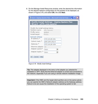
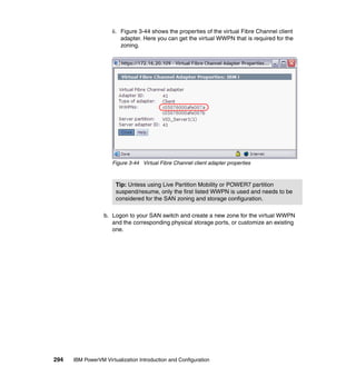
![338 IBM PowerVM Virtualization Introduction and Configuration
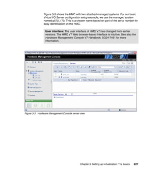
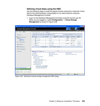
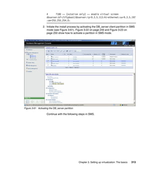
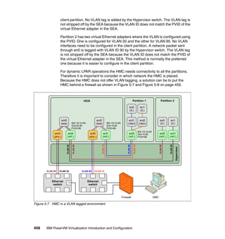
3.5.2 Installing the Virtual I/O Server image using installios
You can also use the installios command on the HMC to install the Virtual I/O
Server image, either stored on the HMC or the Virtual I/O Server install media in
the HMC’s DVD drive. Example 3-40 shows the dialog from the installios
command without options. In our example we installed from the image on the
install media inserted into the HMC’s DVD drive. If you had previously copied this
image to the HMC hard disk, you can specify the location of the copied image
instead of the DVD drive.
Example 3-40 Running installios on the HMC
hscroot@hmc4:~> installios
The following objects of type "managed system" were found. Please
select one:
1. p570_170
2. p570_6A0
Enter a number (1-2): 2
The following objects of type "virtual I/O server partition" were
found. Please select one:
1. VIO_Server1
Enter a number: 1
The following objects of type "profile" were found. Please select one:
1. default
Enter a number: 1
Enter the source of the installation images [/dev/cdrom]: /dev/cdrom
Enter the client's intended IP address: 172.16.20.191
Enter the client's intended subnet mask: 255.255.252.0
Enter the client's gateway: 172.16.20.109
Enter the client's speed [100]: auto
Enter the client's duplex [full]: auto
Would you like to configure the client's network after the
installation [yes]/no? no
Please select an adapter you would like to use for this installation.
(WARNING: The client IP address must be reachable through this adapter!
1. eth0 10.1.1.109](https://image.slidesharecdn.com/sg247940-130416014807-phpapp02/85/IBM-PowerVM-Virtualization-Introduction-and-Configuration-366-320.jpg)
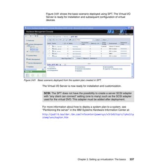
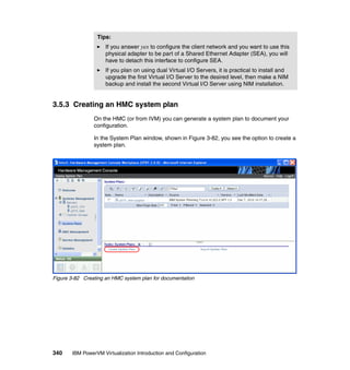
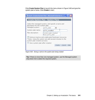
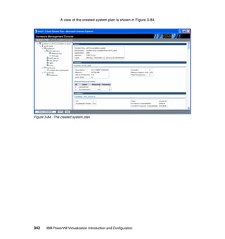
![Chapter 3. Setting up virtualization: The basics 339
2. eth1 172.16.20.109
3. eth2 10.255.255.1
4. eth3
Enter a number (1-4): 2
Retrieving information for available network adapters
This will take several minutes...
The following objects of type "ethernet adapters" were found. Please
select one:
1. ent U9117.MMA.100F6A0-V1-C11-T1 a24e5655040b /vdevice/l-lan@3000000b
n/a virtual
2. ent U789D.001.DQDWWHY-P1-C10-T2 00145e5e1f20
/lhea@23c00100/ethernet@23e00000 n/a physical
3. ent U789D.001.DQDWWHY-P1-C5-T1 001125cb6f64
/pci@800000020000202/pci@1/ethernet@4 n/a physical
4. ent U789D.001.DQDWWHY-P1-C5-T2 001125cb6f65
/pci@800000020000202/pci@1/ethernet@4,1 n/a physical
5. ent U789D.001.DQDWWHY-P1-C5-T3 001125cb6f66
/pci@800000020000202/pci@1/ethernet@6 n/a physical
6. ent U789D.001.DQDWWHY-P1-C5-T4 001125cb6f67
/pci@800000020000202/pci@1/ethernet@6,1 n/a physical
Enter a number (1-6): 3
Enter a language and locale [en_US]: en_US
Here are the values you entered:
managed system = p570_6A0
virtual I/O server partition = VIO_Server1
profile = default
source = /dev/cdrom
IP address = 172.16.20.191
subnet mask = 255.255.252.0
gateway = 172.16.20.109
speed = auto
duplex = auto
configure network = no
install interface = eth1
ethernet adapters = 00:11:25:cb:6f:64
language = en_US
Press enter to proceed or type Ctrl-C to cancel...](https://image.slidesharecdn.com/sg247940-130416014807-phpapp02/85/IBM-PowerVM-Virtualization-Introduction-and-Configuration-367-320.jpg)
![Chapter 3. Setting up virtualization: The basics 347
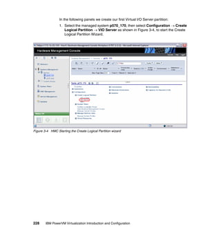
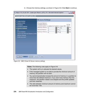
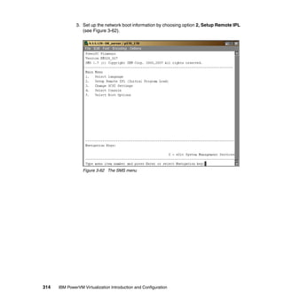
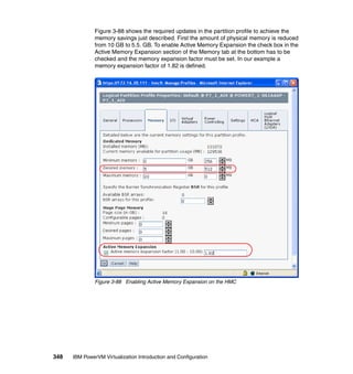
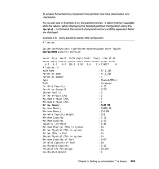
3.6 Active Memory Expansion
The following example shows how to enable Active Memory Expansion for an
existing AIX partition. The partition used in this example initially has 10 GB of
physical memory assigned.
We assume that on the server where the partition is running, another partition
needs more physical memory. Because no spare memory is available, the
memory footprint of the example partition has to be reduced.
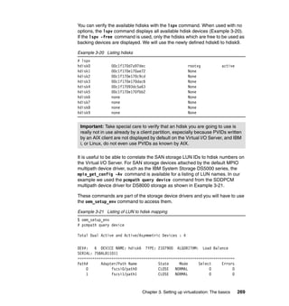
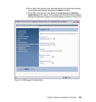
As a first step, the amepat command is run to analyze the workload in the
partition and get a suggestion for a reasonable physical memory size and
memory expansion factor. Example 3-43 shows the amepat command output.
Example 3-43 amepat command example
.
.[Lines omitted for clarity]
.
Active Memory Expansion Modeled Statistics :
-------------------------------------------
Modeled Expanded Memory Size : 10.00 GB
Achievable Compression ratio :2.85
Expansion Modeled True Modeled CPU Usage
Factor Memory Size Memory Gain Estimate
--------- ------------- ------------------ -----------
1.03 9.75 GB 256.00 MB [ 3%] 0.00 [ 0%]
1.22 8.25 GB 1.75 GB [ 21%] 0.00 [ 0%]
1.38 7.25 GB 2.75 GB [ 38%] 0.00 [ 0%]
1.54 6.50 GB 3.50 GB [ 54%] 0.00 [ 0%]
1.67 6.00 GB 4.00 GB [ 67%] 0.00 [ 0%]
1.82 5.50 GB 4.50 GB [ 82%] 0.00 [ 0%]
2.00 5.00 GB 5.00 GB [100%] 0.52 [ 26%]
.
.[Lines omitted for clarity]
.
In this case the optimum memory size is 5.5 GB with a memory expansion factor
of 1.82. With these settings, the operating system in the partition will still see
10 GB of available memory, but the amount of physical memory can be reduced
by almost half. A higher expansion factor means that significantly more CPU
resources will be needed for performing the compression and decompression.](https://image.slidesharecdn.com/sg247940-130416014807-phpapp02/85/IBM-PowerVM-Virtualization-Introduction-and-Configuration-375-320.jpg)
![374 IBM PowerVM Virtualization Introduction and Configuration
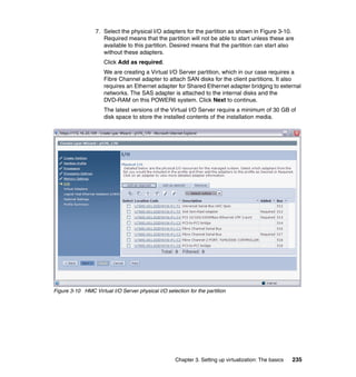
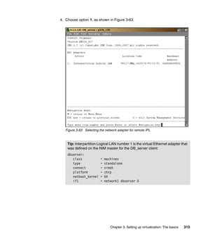
2. Create a cluster on the Virtual I/O Server by using the cluster command.
In our case, we specify hdisk16 as a repository physical volume and hdisk17,
hdisk18 as storage pool physical volumes, as shown in Example 3-54.
Example 3-54 Create a cluster
$ cluster -create -clustername clusterA -repopvs hdisk16 -spname poolA -sppvs -sppvs
hdisk17 hdisk18 -hostname `hostname`
mkcluster: Cluster shared disks are automatically renamed to names such as
cldisk1, [cldisk2, ...] on all cluster nodes. However, this cannot
take place while a disk is busy or on a node which is down or not
reachable. If any disks cannot be renamed now, they will be renamed
later by the clconfd daemon, when the node is available and the disks
are not busy.
Cluster clusterA has been created successfully.
3. After creating the cluster, the physical volumes for a shared storage pool
might get renamed. In this case, the repository disk hdisk16 is renamed to
caa_private0 and storage pool disks hdisk17 and hdisk18 are renamed to
cldisk1 and cldisk2 as shown in Example 3-55.
Example 3-55 Renamed storage pool physical volumes
$ lspv
NAME PVID VG STATUS
hdisk0 00f61aa68974321d rootvg active
hdisk1 00f61aa68ceadd61 None
hdisk2 00f61aa68ceb18ae None
hdisk3 none None
hdisk4 00f61aa66682ec68 None
hdisk5 none None
hdisk6 none None
hdisk7 none None
hdisk8 none None
hdisk9 none None
hdisk10 none None
hdisk11 none None
hdisk12 none None
hdisk13 none None
hdisk14 00f61ab266893de3 None
hdisk15 none None
caa_private0 00f61aa6793ca67c caavg_private active
cldisk1 none None
cldisk2 none None
hdisk19 none None
hdisk20 none None
hdisk21 none None
hdisk22 none None](https://image.slidesharecdn.com/sg247940-130416014807-phpapp02/85/IBM-PowerVM-Virtualization-Introduction-and-Configuration-402-320.jpg)


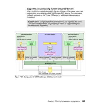
![432 IBM PowerVM Virtualization Introduction and Configuration
Where N is the number of the disk in question; reservation commands are
specific to the multipathing disk driver in use. This parameter is used with
DS4000 disks; it can be different with other disk subsystems.
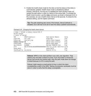
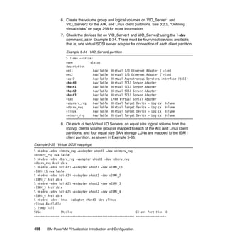
5. On the first Virtual I/O Server, assign the disk to the first partition:
$ mkvdev -vdev hdiskN -vadapter vhostN [ -dev Name ]
Where N is the number of the disk respectively; the vhost in question and the
device name can be chosen to your liking but also left out entirely; the system
will then create a name automatically.
6. On the first Virtual I/O Server, assign the disk to the second partition:
$ mkvdev -f -vdev hdiskN -vadapter vhostN [ -dev Name ]
7. On the second Virtual I/O Server, scan for the disk:
$ cfgdev
8. On the second Virtual I/O Server, change the SCSI reservation of that disk:
$ chdev -dev hdiskN -attr reserve_policy=no_reserve
9. On the second Virtual I/O Server, assign the disk to the first partition:
$ mkvdev -vdev hdiskN -vadapter vhostN [ -dev Name ]
10.On the second Virtual I/O Server, assign the disk to the second partition:
$ mkvdev -f -vdev hdiskN -vadapter vhostN [ -dev Name ]
11.On the first partition, scan for that disk:
# cfgmgr
12.On the first partition, create an enhanced concurrent capable volume group
with a file system:
# mkvg -C -y sharedvg hdiskN
# mklv -y sharedlv -t jfs2 sharedvg 10M
# crfs -v jfs2 -d sharedlv -m /sharedfs
# mount /sharedfs
# touch /sharedfs/testfile
13.The system will inform you that the volume group is not varied on
automatically and that it has to be done manually. Although it is possible to
create an enhanced concurrent capable volume group without cluster
manager software installed, it is not desirable. All accesses to the enhanced
concurrent enabled volume group are not coordinated between both servers,
which can lead to data corruption on this volume group.
Tip: You must specify the -f flag so that an already assigned disk can be
assigned again.](https://image.slidesharecdn.com/sg247940-130416014807-phpapp02/85/IBM-PowerVM-Virtualization-Introduction-and-Configuration-460-320.jpg)

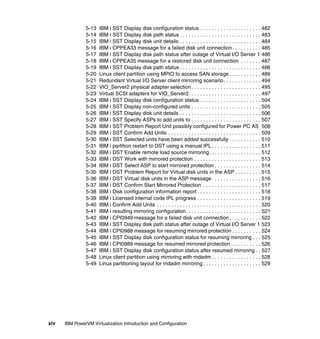
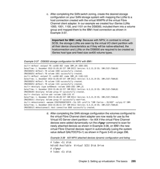
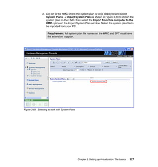
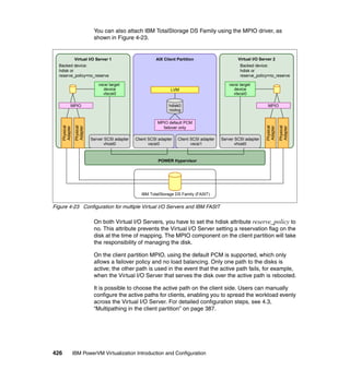
![444 IBM PowerVM Virtualization Introduction and Configuration
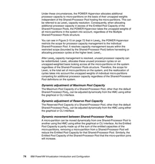
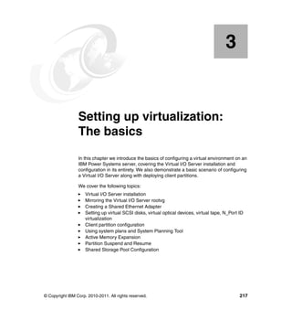
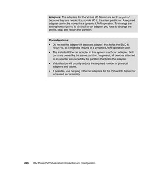
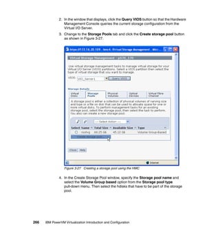
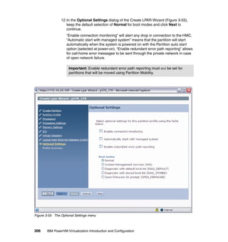
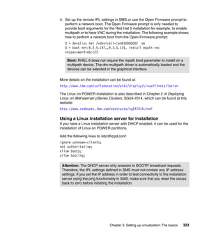
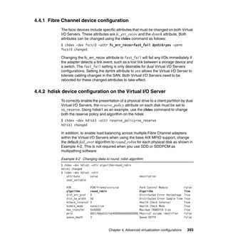
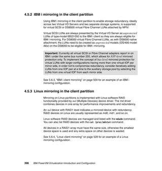
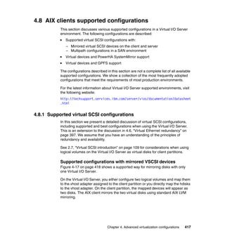
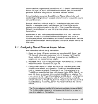
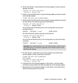
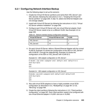
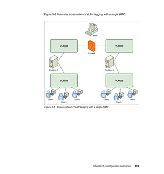
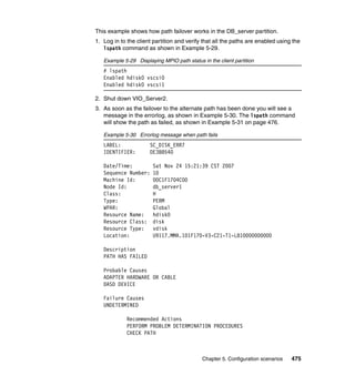
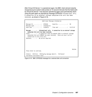
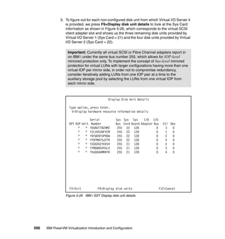
7. In each client partition, define the EtherChannel entering smit and selecting
Devices Communication EtherChannel / IEEE 802.3ad Link
Aggregation Add An EtherChannel / Link Aggregation or using the
smitty etherchannel command. Select the primary adapter, ent0, and press
Enter. Example 5-5 shows the SMIT menu for adding an EtherChannel/Link
Aggregation.
Example 5-5 Add An EtherChannel / Link Aggregation smit menu
Add An EtherChannel / Link Aggregation
Type or select values in entry fields.
Press Enter AFTER making all desired changes.
[Entry Fields]
EtherChannel / Link Aggregation Adapters ent0 +
Enable Alternate Address no +
Alternate Address [] +
Enable Gigabit Ethernet Jumbo Frames no +
Mode standard +
Hash Mode default +
Backup Adapter ent1 +
Automatically Recover to Main Channel yes +
Perform Lossless Failover After Ping Failure yes +
Internet Address to Ping [9.3.4.1]
Number of Retries [] +#
Retry Timeout (sec) [] +#
Esc+1=Help Esc+2=Refresh Esc+3=Cancel Esc+4=List
Esc+5=Reset F6=Command F7=Edit F8=Image
F9=Shell F10=Exit Enter=Do
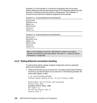
5.2.2 Testing Network Interface Backup
Perform the following steps to verify that the NIB configuration works as
expected. The procedure shows how failover works when the network connection
of a Virtual I/O Server is disconnected. The failover works in the same fashion
when a Virtual I/O Server is rebooted. You can test this by rebooting
VIO_Server1 instead of unplugging the network cable in step 2.
Tip: The following message, which appears in the errorlog when the
EtherChannel is created, can be ignored:
5561971C 1123194707 P S ent2 UNSUPPORTED IOCTL IN DEVICE DRIVER](https://image.slidesharecdn.com/sg247940-130416014807-phpapp02/85/IBM-PowerVM-Virtualization-Introduction-and-Configuration-472-320.jpg)
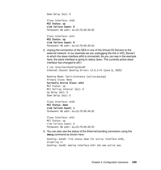


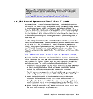
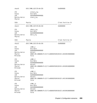
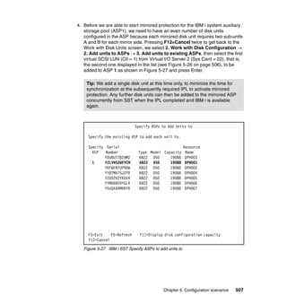
![Chapter 5. Configuration scenarios 491
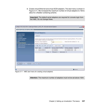
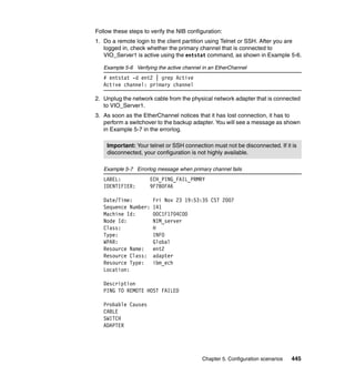
Testing multipathing on the Linux client
To verify that your device mapper multipath configuration works as expected,
perform the following steps:
1. Verify that both paths are active using the multipath command:
# multipath -ll
mpath0 (3600a0b80000bdc160000052847436d1e) dm-0 AIX,VDASD
[size=20G][features=0][hwhandler=0]
_ round-robin 0 [prio=1][active]
_ 0:0:1:0 sda 8:0 [active][ready]
_ round-robin 0 [prio=1][enabled]
_ 1:0:1:0 sdb 8:16 [active][ready]
2. Shut down one of the Virtual I/O Servers. In this example VIO_Server1 is shut
down. In var/log/messages you will see the following messages:
ibmvscsi: Partner adapter not ready
ibmvscsi: error after reset
Dec 7 15:46:57 localhost kernel: ibmvscsi: Virtual adapter failed rc 2!
Dec 7 15:46:57 localhost kernel: rpa_vscsi: SPR_VERSION: 16.a
Dec 7 15:46:57 localhost kernel: ibmvscsi: Partner adapter not ready
Dec 7 15:46:57 localhost kernel: ibmvscsi: error after reset
device-mapper: multipath: Failing path 8:0.
Dec 7 15:47:01 localhost kernel: device-mapper: multipath: Failing path 8:0.
Dec 7 15:47:01 localhost multipathd: 8:0: reinstated
Dec 7 15:47:01 localhost multipathd: mpath0: remaining active paths: 2
Dec 7 15:47:01 localhost multipathd: sda: readsector0 checker reports path is down
Dec 7 15:47:01 localhost multipathd: checker failed path 8:0 in map mpath0
Dec 7 15:47:01 localhost multipathd: mpath0: remaining active paths: 1
Dec 7 15:47:06 localhost multipathd: sda: readsector0 checker reports path is down
Tip: For path management, you can also use the interactive shell, which
can be started using the multipathd -k command. You can enter an
interactive command, you can enter help to get a list of available
commands, or you can enter CTRL-D to quit.](https://image.slidesharecdn.com/sg247940-130416014807-phpapp02/85/IBM-PowerVM-Virtualization-Introduction-and-Configuration-519-320.jpg)
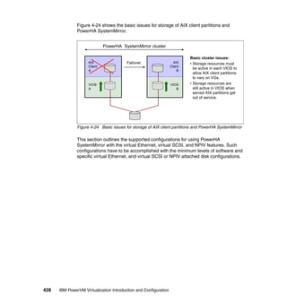
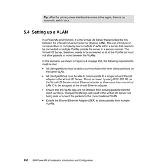
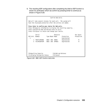
![492 IBM PowerVM Virtualization Introduction and Configuration
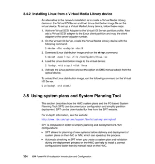
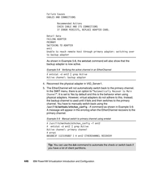
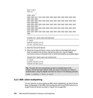
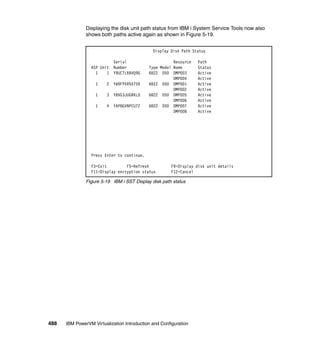
3. When using the multipath command to display the path status, one path
must be marked as failed as shown here:
# multipath -ll
sda: checker msg is "readsector0 checker reports path is down"
mpath0 (3600a0b80000bdc160000052847436d1e) dm-0 AIX,VDASD
[size=20G][features=0][hwhandler=0]
_ round-robin 0 [prio=0][enabled]
_ 0:0:1:0 sda 8:0 [failed][faulty]
_ round-robin 0 [prio=1][active]
_ 1:0:1:0 sdb 8:16 [active][ready]
[root@localhost ~]#
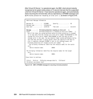
4. Restart the Virtual I/O Server. After the Virtual I/O Server is rebooted, you will
see the following messages in /var/adm/messages:
ibmvscsic: sent SRP login
ibmvscsi: host srp version: 16.a, host partition VIO_Server1 (1), OS 3, max io
1048576
Dec 7 15:50:36 localhost last message repeated 9 times
Dec 7 15:50:39 localhost kernel: ibmvscsi: partner initialized
Dec 7 15:50:39 localhost kernel: ibmvscsic: sent SRP login
Dec 7 15:50:39 localhost kernel: ibmvscsi: SRP_LOGIN succeeded
Dec 7 15:50:39 localhost kernel: ibmvscsi: host srp version: 16.a, host partition
VIO_Server1 (1), OS 3, max io 1048576
Dec 7 15:50:41 localhost multipathd: sda: readsector0 checker reports path is down
Dec 7 15:50:46 localhost multipathd: sda: readsector0 checker reports path is up
Dec 7 15:50:46 localhost multipathd: 8:0: reinstated
Dec 7 15:50:46 localhost multipathd: mpath0: remaining active paths: 2
5. When using the multipath command to display the path status, both paths
must be active again:
# multipath -ll
mpath0 (3600a0b80000bdc160000052847436d1e) dm-0 AIX,VDASD
[size=20G][features=0][hwhandler=0]
_ round-robin 0 [prio=1][enabled]
_ 0:0:1:0 sda 8:0 [active][ready]
_ round-robin 0 [prio=1][active]
_ 1:0:1:0 sdb 8:16 [active][ready]](https://image.slidesharecdn.com/sg247940-130416014807-phpapp02/85/IBM-PowerVM-Virtualization-Introduction-and-Configuration-520-320.jpg)
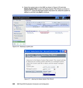
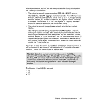
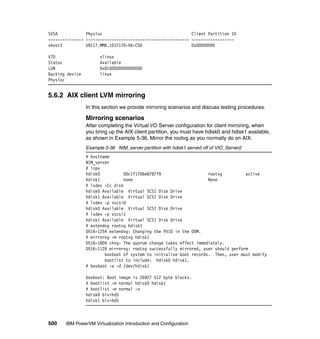
![Chapter 5. Configuration scenarios 493
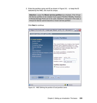
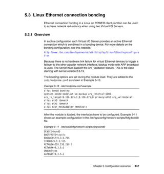
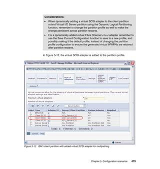
Using NPIV for multipathing
The multipath configuration using NPIV is basically the same as for a physical
Fibre Channel device. To set up a multipath device using NPIV you need to
assign the virtual Fibre Channels’ WWPNs to the SAN logical drives. Virtual
Fibre Channel’s WWPNs can be retrieved from the partition profile at the HMC
interface. Additionally, you can list the WWPNs directly from Linux as follows:
root@Power7-2-RHEL ~]# cat /sys/class/fc_host/host5/port_name
0xc0507603039e0003
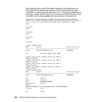
Two WWPNs for each NPIV port are required in order to support Live Partition
Mobility. When configuring the SAN, you must be sure to assign both WWPNs to
each LUN. In the case of multipath, that will be a total of 4 WWPNs as follows:
0xc0507603039e0002
0xc0507603039e0003
0xc0507603039e0008
0xc0507603039e0009
After the mappings are done on the Virtual I/O Server and the WWPNs are
assigned to the SAN disk, the paths are automatically detected by Linux.
[root@Power7-2-RHEL ~]# lsscsi -v|grep rport
5:0:0:0] disk IBM 2107900 .278 /dev/sdc
dir: /sys/bus/scsi/devices/5:0:0:0
[/sys/devices/vio/30000038/host5/rport-5:0-0/target5:0:0/5:0:0:0]
[6:0:0:0] disk IBM 2107900 .278 /dev/sdd
dir: /sys/bus/scsi/devices/6:0:0:0
[/sys/devices/vio/30000039/host6/rport-6:0-0/target6:0:0/6:0:0:0]
The multipath devices can be listed with multipath -ll command as follows:
[root@Power7-2-RHEL ~]# multipath -ll
mpath1 (36005076304ffc12c0000000000001020) dm-2 IBM,2107900
[size=15G][features=0][hwhandler=0][rw]
_ round-robin 0 [prio=2][active]
_ 5:0:0:0 sdc 8:32 [active][ready]
_ 6:0:0:0 sdd 8:48 [active][ready]
Tip: The fast_io_fail_tmo attribute of the fc_remote_port can be enabled in
order to change the time it takes to failover when a path fails. The setup differs
from distribution to another and it can be enabled by default. To change the
timeout to 5 seconds set fast_io_fail_tmo as follows:
echo 5 > /sys/class/fc_remote_ports/rport-3:0-0/fast_io_fail_tmo](https://image.slidesharecdn.com/sg247940-130416014807-phpapp02/85/IBM-PowerVM-Virtualization-Introduction-and-Configuration-521-320.jpg)


![530 IBM PowerVM Virtualization Introduction and Configuration
SLES partitioning
When partitioning on SLES, the first partition on each disk must be of type
FAT16. Create the following partitioning scheme to avoid the need of doing
manual mirroring:
1. Create the RAID1 partition, but do not create a filesystem on it or mount it.
Then create an LVM Volume Group and create an Logical Volume for swap
and an Logical Volume for / (root partition):
/dev/sda1 64M FAT16 Boot
/dev/sda2 RAID (0xfd)
2. Proceed with the installation as usual.
3. After the installation completes, look in /etc/lilo.conf at the boot = line. Find
the other device that is in the mirrored pair and add a similar line to lilo.conf,
except make it a clone = line rather than a boot = line. The lilo.conf file must
look as follows:
boot = /dev/disk/by-id/scsi-3500507670cc05da0-part1
clone = /dev/dev/disk/by-id/scsi-scsi-3500507670cc05cf7-part1
4. After editing lilo.conf, run the nlilo command to load the new configuration.
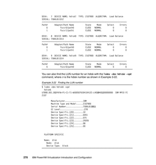
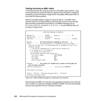
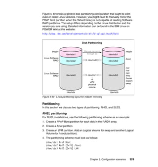
Testing mirroring on the Linux client
If a virtualized disk is not accessible, you will see the disk marked as failed as
shown in Example 5-40.
Example 5-40 cat /proc/mdstat showing lost disk
[root@op720-1-client4 ~]# cat /proc/mdstat
Personalities : [raid1]
md1 : active raid1 sdb3[1] sda3[0]
1953728 blocks [2/2] [UU]
md2 : active raid1 sdb4[1] sda4[2](F)
21794752 blocks [2/1] [_U]
md0 : active raid1 sdb2[1] sda2[2](F)
98240 blocks [2/1] [_U]
unused devices: <none>](https://image.slidesharecdn.com/sg247940-130416014807-phpapp02/85/IBM-PowerVM-Virtualization-Introduction-and-Configuration-558-320.jpg)
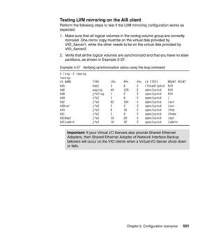
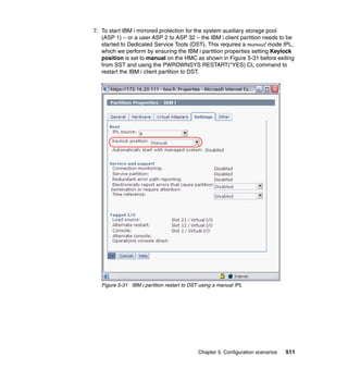
![Chapter 5. Configuration scenarios 531
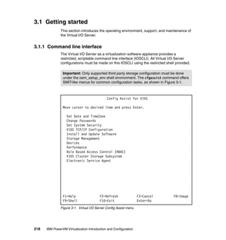
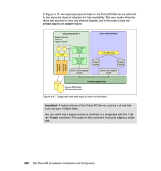
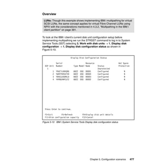
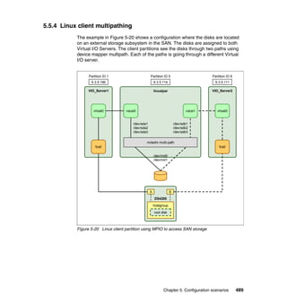
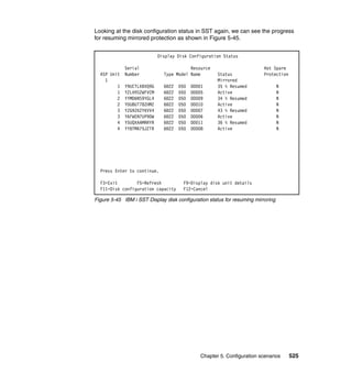
To recover the disk, perform the following steps:
1. Set the disk to faulty status:
# mdadm --manage --set-faulty /dev/md0 /dev/sda2
# mdadm --manage --set-faulty /dev/md1 /dev/sda3
# mdadm --manage --set-faulty /dev/md2 /dev/sda4
2. Remove the device:
# mdadm --manage --remove /dev/md0 /dev/sda2
# mdadm --manage --remove /dev/md1 /dev/sda3
# mdadm --manage --remove /dev/md2 /dev/sda4
3. Rescan the device (choose the corresponding path):
echo 1 > /sys/class/scsi_device/0:0:1:0/device/rescan
4. Hot add the device to mdadm:
# mdadm --manage --add /dev/md0 /dev/sda2
# mdadm --manage --add /dev/md1 /dev/sda3
# mdadm --manage --add /dev/md2 /dev/sda4
5. Verify that resynchronization is running:
# cat /proc/mdstat
Personalities : [raid1]
md1 : active raid1 sda3[0] sdb3[1]
1953728 blocks [2/2] [UU]
md2 : active raid1 sda4[2] sdb4[1]
21794752 blocks [2/1] [_U]
[=>...................] recovery = 5.8% (1285600/21794752)
finish=8.2min speed=41470K/sec
md0 : active raid1 sda2[0] sdb2[1]
98240 blocks [2/2] [UU]
Important: Never reboot the other Virtual I/O Server as long as the recovery
is not finished.](https://image.slidesharecdn.com/sg247940-130416014807-phpapp02/85/IBM-PowerVM-Virtualization-Introduction-and-Configuration-559-320.jpg)


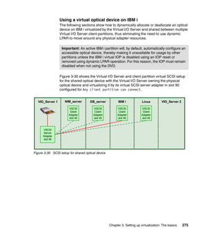
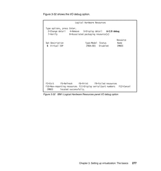
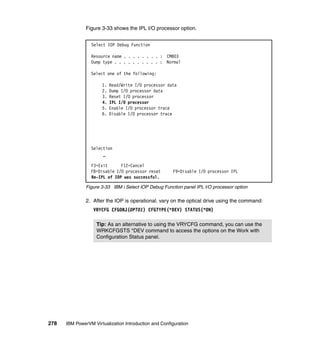
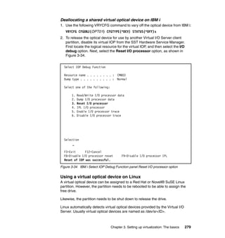
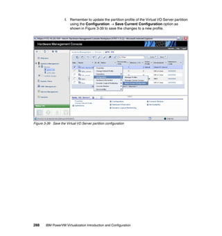
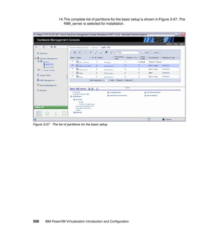
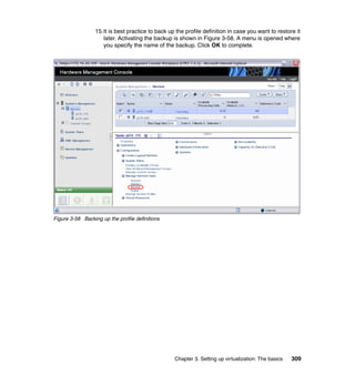
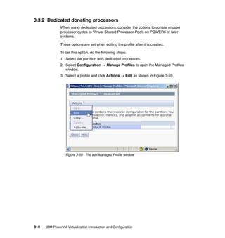
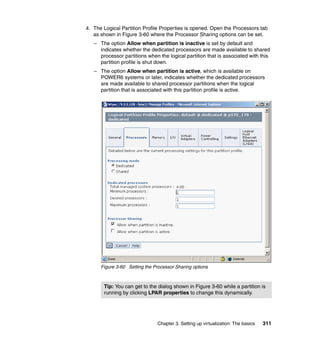
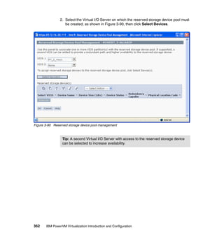
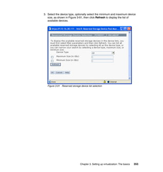
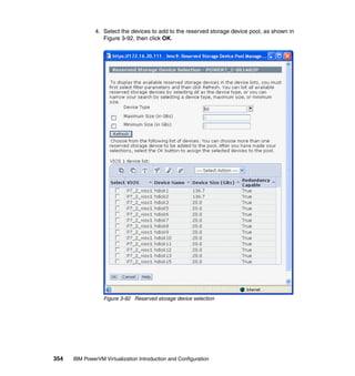
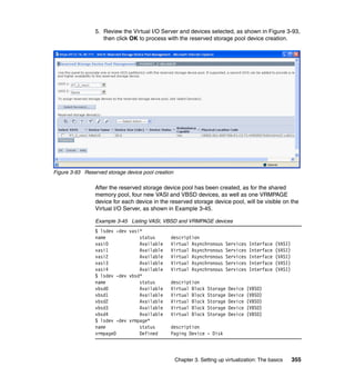
The document is an updated technical guide on IBM PowerVM virtualization, focusing on both basic and advanced configurations of the virtual I/O server and its clients, incorporating new Power7 technologies. It provides detailed coverage of various aspects including virtualization technologies, operating system support, hardware compatibility, and security in virtualized environments. The guide is part of the International Technical Support Organization and is intended for users implementing or managing IBM virtualization solutions.