This document provides an overview and introduction of the IBM Power S1014, S1022s, S1022, and S1024 servers. It describes the key features and specifications of these systems including their IBM Power10 processors, memory support, I/O and storage options, operating system support, and more. It also discusses the IBM solutions and technologies that can be used with these Power servers, such as the IBM PowerSC management framework, PowerVC virtualization software, and Red Hat OpenShift Container Platform.


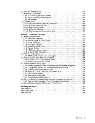


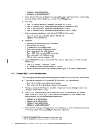


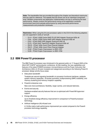
![Chapter 2. Architecture and technical overview 51
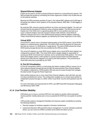
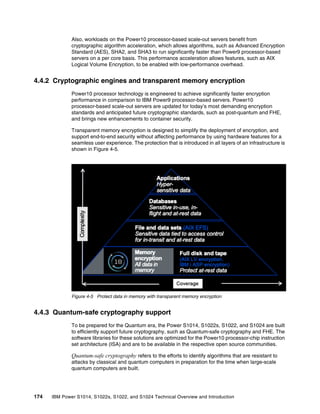
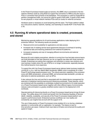
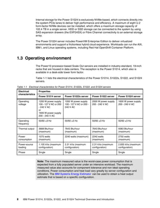
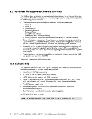
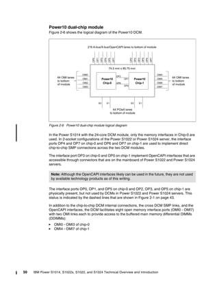
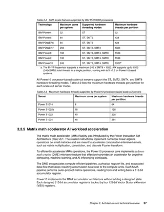
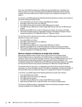
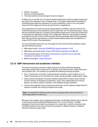
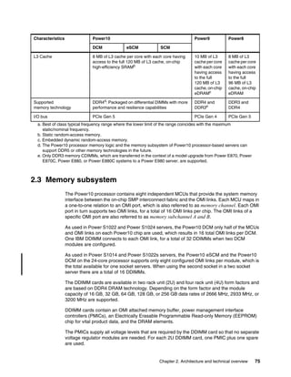
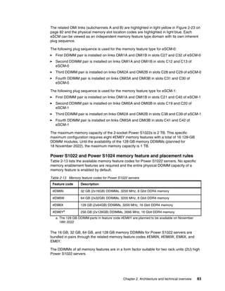
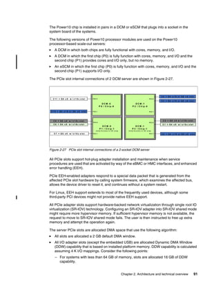
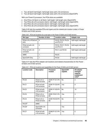
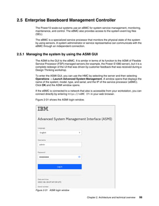
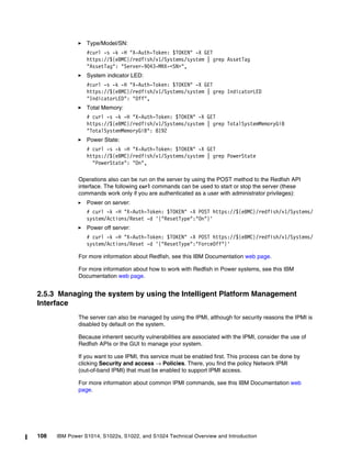
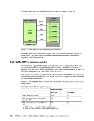
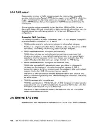
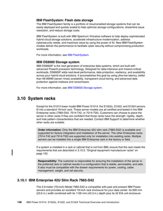
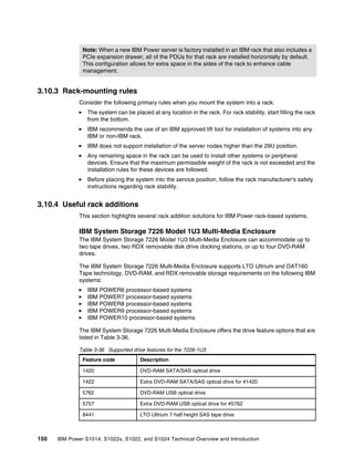
Finally, the DCM also offers differential Peripheral Component Interconnect Express version
5.0 interface busses (PCIe Gen 5) with a total of 64 lanes. Every chip of the DCM contributes
32 PCIe Gen5 lanes, which are grouped in two PCIe host bridges (E0, E1) with 16 PCIe Gen5
lanes each:
E0, E1 on chip-0
E0, E1 on chip-1
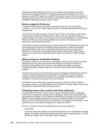
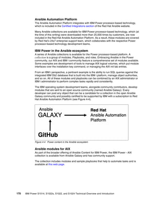
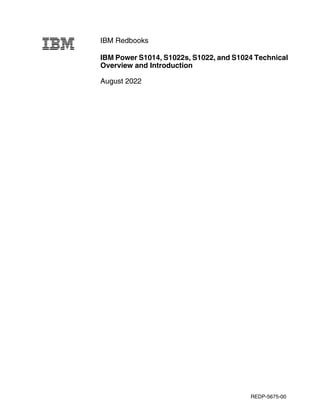
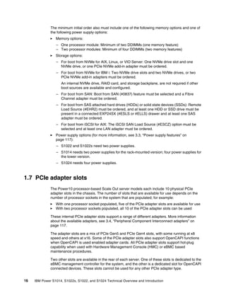
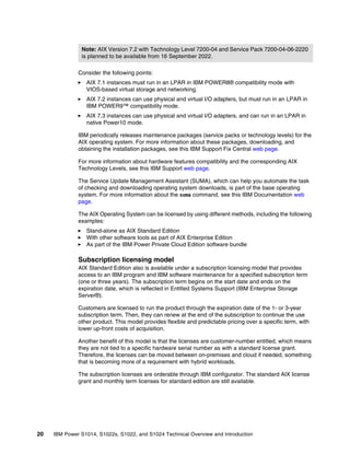
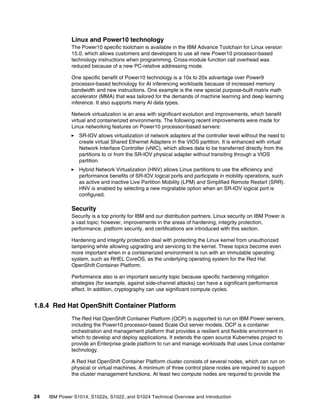
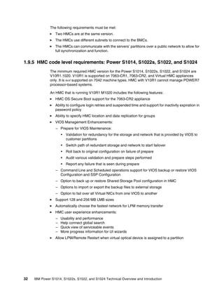
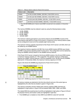
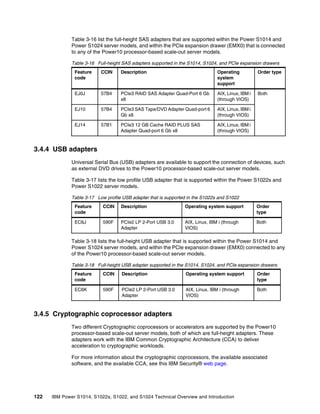
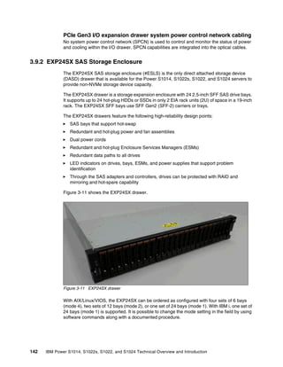
Figure 2-7 shows the physical diagram of the Power10 DCM. Interface ports that are not used
by Power S1022 and Power S1024 servers (OP0, OP1, and OP5 on chip-0 and OP2, OP3,
and OP5 on chip-1) are shown, but no specification labels are shown.
Figure 2-7 Power10 dual-chip module physical diagram
Note: The OMI interfaces are driven by eight on-chip memory controller units (MCUs) and
are implemented in two separate physical building blocks that lie in opposite areas at the
outer edge of the Power10 processor chip. One MCU directly controls one OMI port.
Therefore, a total of 16 OMI ports (OMI0 - OMI7 on chip-0 and OMI0 - OMI7 on chip-1) are
physically present on a Power10 DCM. However, because the chips on the DCM are tightly
integrated and the aggregated memory bandwidth of eight OMI ports culminates at
1 TBps, only half of the OMI ports are active. OMI4 to OMI7 on chip-0 and OMI0 to OMI3 of
chip-1 are disabled.
2 x9 SMP 32 Gbps
Power10
Chip-0
AXON
AXON
AXON
AXON
AXON
AXON
AX
AX
OMI [0:3]
OMI
I/O
MISC
PCIe
PCIe
E0
E1
OP3
OP0
OP5
OP7
OP4 OP1
Power10
Chip-1
AXON
AXON
AXON
AXON
AXON
AXON
AX
AX
OMI
OMI [4:7]
I/O
MISC
PCIe
PCIe
E0
E1
OP3
OP0
OP5
OP7
OP4 OP1
OP6 OP2
OP6 OP2
1 x16 Gen4 or
2 x8 Gen4 or
1 x8, 2 x4 Gen4 or
1 x8 Gen5, 1 x8 Gen4 or
1 x8 Gen5, 2 x4 Gen4
1 x16 Gen4 or
2 x8 Gen4 or
1 x8, 2 x4 Gen4 or
1 x8 Gen5, 1 x8 Gen4 or
1 x8 Gen5, 2 x4 Gen4
2 x8 OpenCAPI 32 Gbps
1 x16 Gen4 or
2 x8 Gen4 or
1 x8, 2 x4 Gen4 or
1 x8 Gen5, 1 x8 Gen4 or
1 x8 Gen5, 2 x4 Gen4
1 x16 Gen4 or
2 x8 Gen4 or
1 x8, 2 x4 Gen4 or
1 x8 Gen5, 1 x8 Gen4 or
1 x8 Gen5, 2 x4 Gen4
2 x8 OpenCAPI 32 Gbps
2 x9 SMP 32 Gbps
2 x9 SMP 32 Gbps
2 x9 SMP 32 Gbps
64 open memory interface
lanes (8 x8) 32 Gbps
64 open memory interface
lanes (8 x8) 32 Gbps](https://image.slidesharecdn.com/ibmpower10-230912025237-2589e74c/85/IBM-Power10-pdf-65-320.jpg)
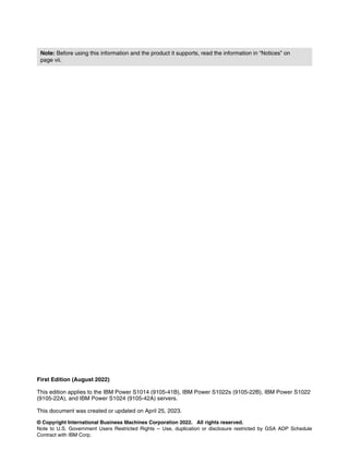
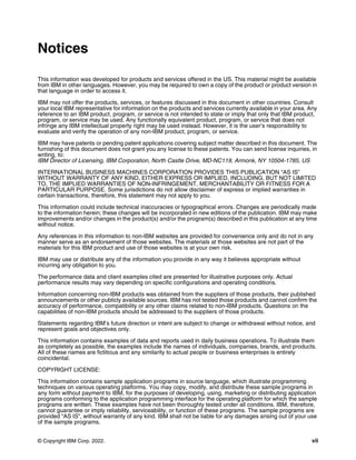
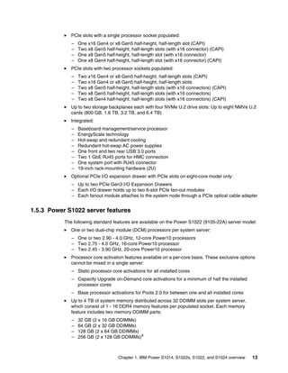
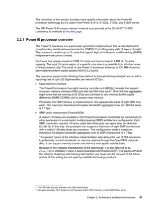
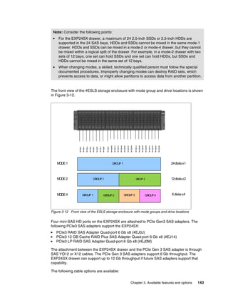
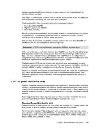
![Chapter 2. Architecture and technical overview 53
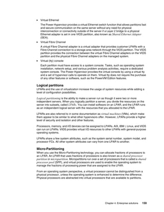
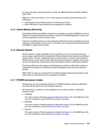
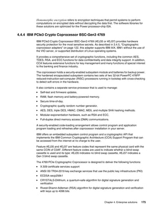
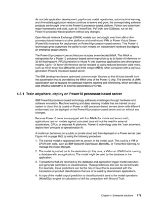
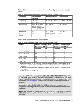
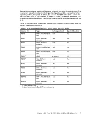
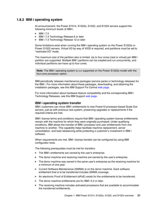
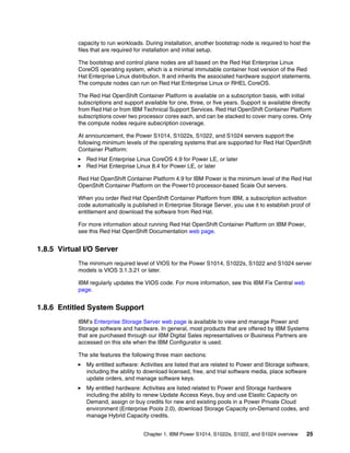
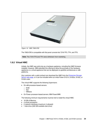
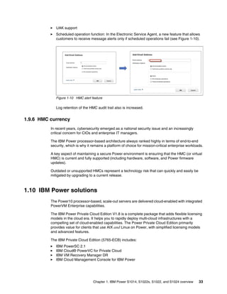
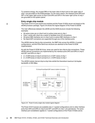
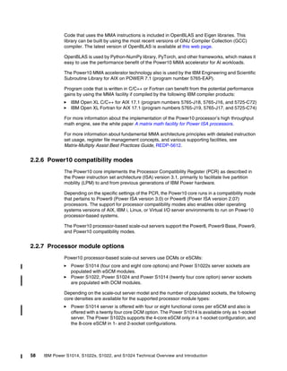
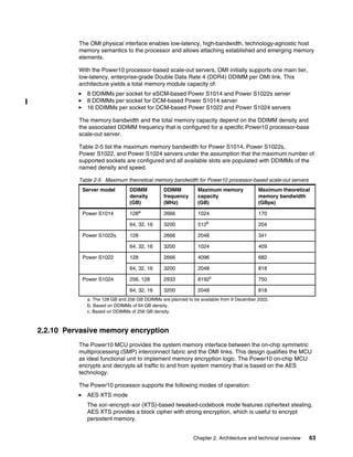
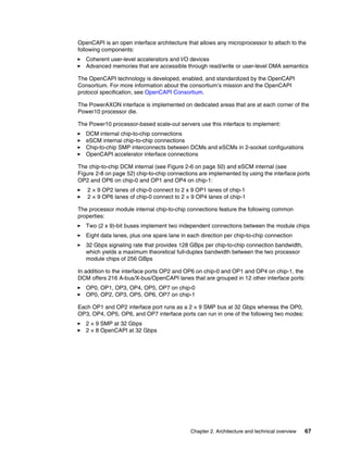
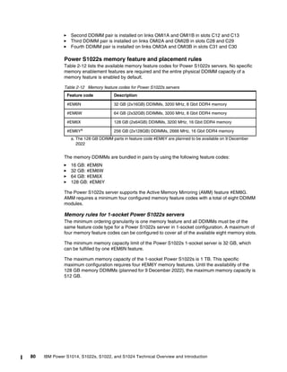
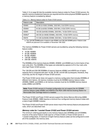
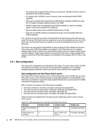
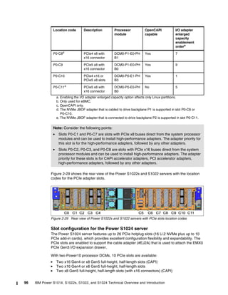
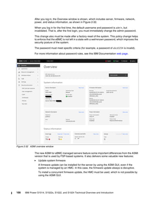
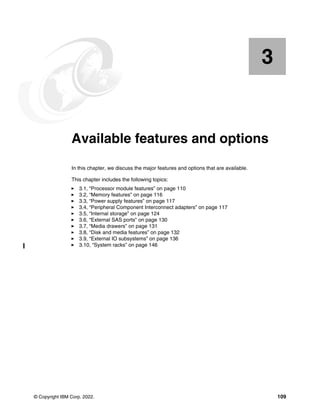
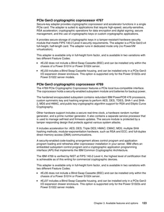
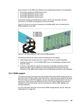
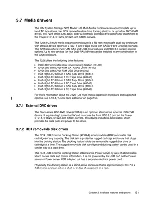
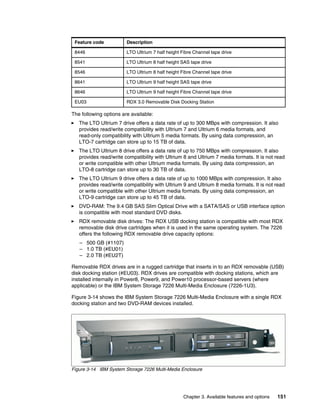
Figure 2-3 on page 45 shows the logical system diagram of the Power S1014 1-socket server
based on a single eSCM.
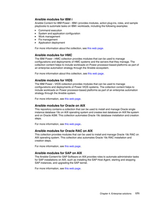
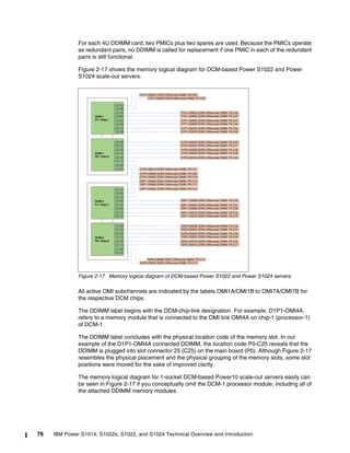
However, in 2-socket eSCM configurations of the Power S1022s server, the interface ports
OP4 and OP7 on chip-0 and OP6 and OP7 on chip-1 of the processor module are active and
used to implement direct chip-to-chip SMP connections between the two eSCM modules.
Figure 2-2 on page 44 shows logical system diagram of the Power S1022s 2-socket server
that is based on two eSCM modules. (The 1-socket constellation can easily be deduced from
Figure 2-2 on page 44 if eSCM-1 is conceptually omitted.)
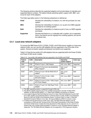
As with the DCM, the eSCM offers differential PCIe Gen 5 with a total of 64 lanes. Every chip
of the eSCM contributes 32 PCIe Gen5 lanes, which are grouped in two PCIe host bridges
(E0, E1) with 16 PCIe Gen5 lanes each:
E0, E1 on chip-0
E0, E1 on chip-1
Figure 2-9 shows the physical diagram of the Power10 entry single chip module. The most
important difference in comparison to the physical diagram of the Power10 DCM that is
shown in Figure 2-7 on page 51 is that chip-1 has no active cores or memory interfaces. Also,
because the eSCM does not support any OpenCAPI connectivity, the interface port OP3 on
chip-0 and OP0 on chip-1 are disabled.
Figure 2-9 Power10 entry single chip module physical diagram
2 x9 SMP 32 Gbps
Power10
Chip-0
AXON
AXON
AXON
AXON
AXON
AXON
AX
AX
OMI [0:3]
OMI
I/O
MISC
PCIe
PCIe
E0
E1
OP3
OP0
OP5
OP7
OP4 OP1
Power10
Switch
Chip-1
AXON
AXON
AXON
AXON
AXON
AXON
AX
AX
OMI
OMI [4:7]
I/O
MISC
PCIe
PCIe
E0
E1
OP3
OP0
OP5
OP7
OP4 OP1
OP6 OP2
OP6 OP2
1 x16 Gen4 or
2 x8 Gen4 or
1 x8, 2 x4 Gen4 or
1 x8 Gen5, 1 x8 Gen4 or
1 x8 Gen5, 2 x4 Gen4
1 x16 Gen4 or
2 x8 Gen4 or
1 x8, 2 x4 Gen4 or
1 x8 Gen5, 1 x8 Gen4 or
1 x8 Gen5, 2 x4 Gen4
1 x16 Gen4 or
2 x8 Gen4 or
1 x8, 2 x4 Gen4 or
1 x8 Gen5, 1 x8 Gen4 or
1 x8 Gen5, 2 x4 Gen4
1 x16 Gen4 or
2 x8 Gen4 or
1 x8, 2 x4 Gen4 or
1 x8 Gen5, 1 x8 Gen4 or
1 x8 Gen5, 2 x4 Gen4
2 x9 SMP 32 Gbps
2 x9 SMP 32 Gbps
2 x9 SMP 32 Gbps
64 open memory interface
lanes (8 x8) 32 Gbps](https://image.slidesharecdn.com/ibmpower10-230912025237-2589e74c/85/IBM-Power10-pdf-67-320.jpg)
![Chapter 2. Architecture and technical overview 55
The SMT8 core supports automatic workload balancing to change the operational SMT
thread level. Depending on the workload characteristics, the number of threads that is running
on one chiplet can be reduced from four to two and even further to only one active thread. An
individual thread can benefit in terms of performance if fewer threads run against the core’s
executions resources.
Micro-architecture performance and efficiency optimization lead to a significant improvement
of the performance per watt signature compared with the previous Power9 core
implementation. The overall energy efficiency per socket is better by a factor of approximately
2.6, which demonstrates the advancement in processor design that is manifested by the
Power10 processor.
The Power10 processor core includes the following key features and improvements that affect
performance:
Enhanced load and store bandwidth
Deeper and wider instruction windows
Enhanced data prefetch
Branch execution and prediction enhancements
Instruction fusion
Enhancements in the area of computation resources, working set size, and data access
latency are described next. The change in relation to the Power9 processor core
implementation is provided in square parentheses.
Enhanced computation resources
The following computational resource enhancements are available:
Eight vector scalar unit (VSU) execution slices, each supporting 64-bit scalar or 128-bit
single instructions multiple data (SIMD) [+100% for permute, fixed-point, floating-point,
and crypto (Advanced Encryption Standard (AES)/SHA) +400% operations].
Four units for matrix math accelerator (MMA) acceleration each capable of producing a
512-bit result per cycle (new) [+400% Single and Double precision FLOPS plus support for
reduced precision AI acceleration].
Two units for quad-precision floating-point and decimal floating-point operations instruction
types
Larger working sets
The following major changes were implemented in working set sizes:
L1 instruction cache: 2 x 48 KB 6-way (96 KB total); +50%
L2 cache: 2 MB 8-way; +400%
L2 translation lookaside buffer (TLB): 2 x 4K entries (8K total); +400%
Data access with reduced latencies
The following major changes reduce latency for load data:
L1 data cache access at four cycles nominal with zero penalty for store-forwarding;
(- 2 cycles) for store forwarding
L2 data access at 13.5 cycles nominal (-2 cycles)
L3 data access at 27.5 cycles nominal (-8 cycles)
Translation lookaside buffer (TLB) access at 8.5 cycles nominal for effective-to-real
address translation (ERAT) miss, including for nested translation (-7 cycles)](https://image.slidesharecdn.com/ibmpower10-230912025237-2589e74c/85/IBM-Power10-pdf-69-320.jpg)
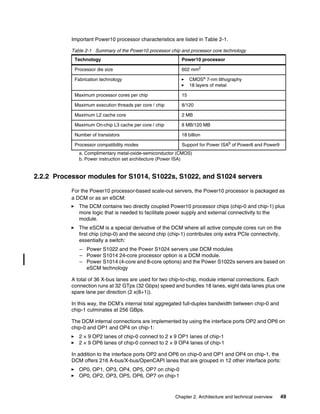
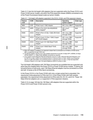
![60 IBM Power S1014, S1022s, S1022, and S1024 Technical Overview and Introduction
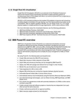
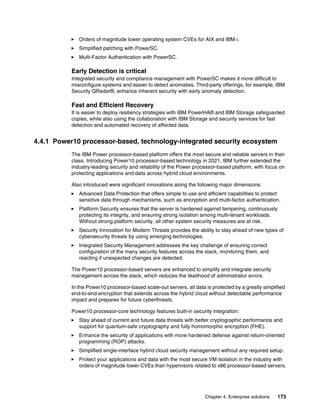
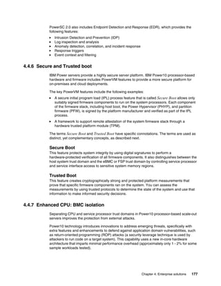
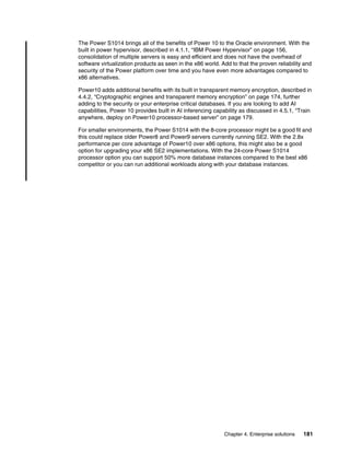
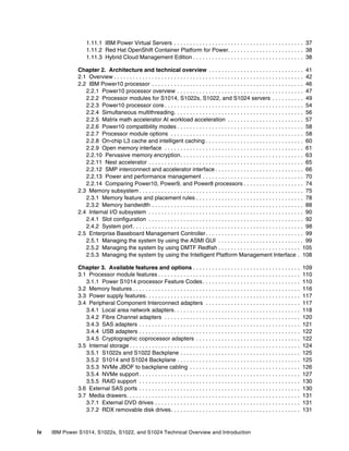
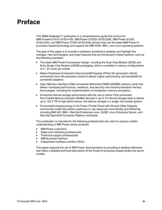
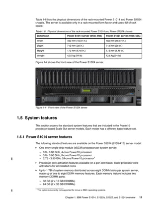
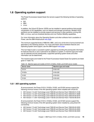
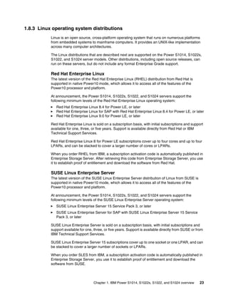
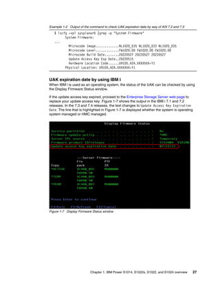
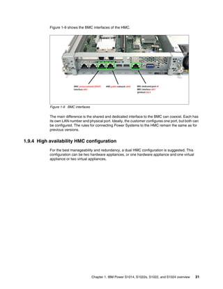
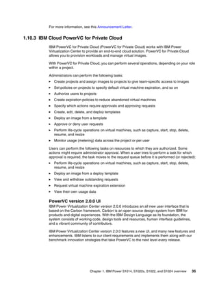
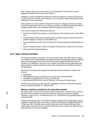
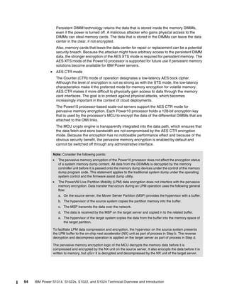
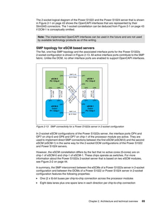
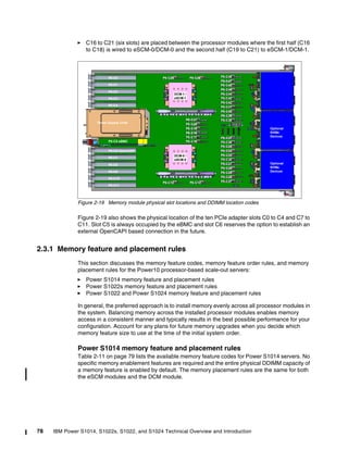
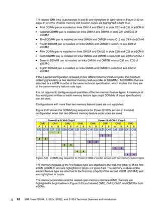
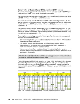
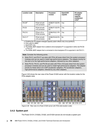
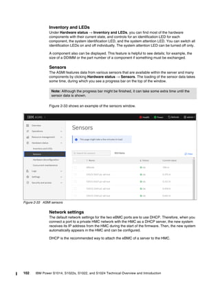
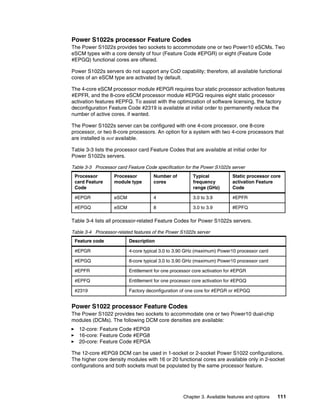
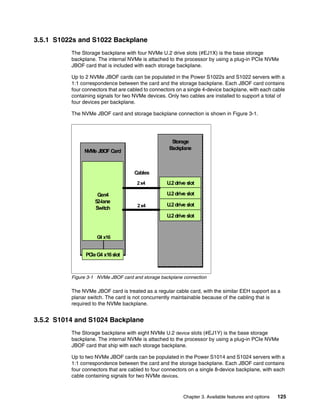
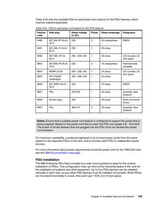
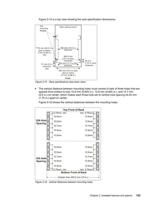
Table 2-4 lists the processor module options that are available for Power10 processor-based
scale-out servers. The list is sorted by increasing order of the processor module capacity.
Table 2-4 Processor module options for Power10 processor-based scale-out servers
For each processor module option the module type (eSCM / DCM), the support for CUoD, the
availability of the Pools 2.0 option, and the minimum number of sockets that must be
populated are indicated.
Power10 processors automatically optimize their core frequencies based on workload
requirements, thermal conditions, and power consumption characteristics. Therefore, each
processor module option that is listed is associated with a processor core frequency range
within which the DCM or eSCM cores typically operate.
Depending on the different physical characteristics of the Power S1022 and Power S1024
servers. two distinct, model-specific frequency ranges are available for processor modules
with 12- and 16-core density.
The last four columns of Table 2-4 list the availability matrix between a specific processor
module capacity and frequency specification on one side and the Power10 processor-base
scale-out server models on the other side. (Available combinations are labeled with “X” and
unavailable combinations are indicated by a “—” hyphen.)
2.2.8 On-chip L3 cache and intelligent caching
The Power10 processor includes a large on-chip L3 cache of up to 120 MB with a NUCA
architecture that provides mechanisms to distribute and share cache footprints across a set of
L3 cache regions. Each processor core can access an associated local 8 MB of L3 cache. It
also can access the data in the other L3 cache regions on the chip and throughout the
system.
Note: The static activation usage model, the CUoD technology usage model, and the
Power Private Cloud Shared Utility Capacity (Power Enterprise Pools 2.0) offering models
are all mutually exclusive in respect to each other.
Module
capacity
Module
type
CUoD
support
Pools2.0
option
Typical
frequency
range
[GHz]
Minimum
quantity
per
server
Power
S1014
Power
S1022s
Power
S1022
Power
S1024
4-core eSCM No No 3.0 - 3.9 1 X X — —
8-core eSCM No No 3.0 - 3.9 1 X X — —
12-core DCM Yes Yes 2.9 - 4.0 1 — — X —
3.4 - 4.0 1 — — — X
16-core DCM Yes Yes 2.75 - 4.0 2 — — X —
3.1 - 4.0 2 — — — X
20-core DCM Yes Yes 2.45 - 3.9 2 — — X —
24-core DCM No No 2.75 - 3.9 1 X — — —
24-core DCM Yes Yes 2.75 - 3.9 2 — — — X](https://image.slidesharecdn.com/ibmpower10-230912025237-2589e74c/85/IBM-Power10-pdf-74-320.jpg)
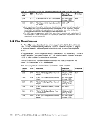
![72 IBM Power S1014, S1022s, S1022, and S1024 Technical Overview and Introduction
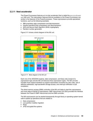
Table 2-6, Table 2-7, Table 2-8, and Table 2-9 show the power saving mode, the static mode
frequencies, and the frequency ranges of the MPM for all processor module types that are
available for the Power S1014, Power S1022s, Power S1022, and Power S1024 servers.
Table 2-6 Characteristic frequencies and frequency ranges for Power S1014 servers
Table 2-7 Characteristic frequencies and frequency ranges for Power S1022s servers
Table 2-8 Characteristic frequencies and frequency ranges for Power S1022 servers
Table 2-9 Characteristic frequencies and frequency ranges for Power S1024 servers
The controls for all power saver modes are available on the Advanced System Management
Interface (ASMI) and can be dynamically modified. A system administrator can also use the
Hardware Management Console (HMC) to set power saver mode or to enable static mode or
MPM.
Note: For all Power10 processor-based scale-out systems, the MPM is enabled by default.
Feature
code
Cores per
module
Power saving
mode frequency
[GHz]
Static mode
frequency
[GHz]
Maximumperformancemode
frequency range
[GHz]
#EPG0 4a
a. Processor is eSCM based
2.0 3.0 3.0 to 3.90 (max)
#EPG2 8 2.0 3.0 3.0 to 3.90 (max)
#EPH8 24b
b. Processor is DCM based
2.0 2.75 2.75 - 3.90 (max)
Feature
code
Cores per
eSCM
Power saving
mode frequency
[GHz]
Static mode
frequency
[GHz]
Maximumperformancemode
frequency range
[GHz]
#EPGR 4 2.0 3.0 3.0 to 3.90 (max)
#EPGQ 8 2.0 3.0 3.0 to 3.90 (max)
Feature
code
Cores per
dual-chip
module
Power saving
mode frequency
[GHz]
Static mode
frequency
[GHz]
Maximumperformancemode
frequency range
[GHz]
#EPG9 12 2.0 2.90 2.90 to 4.0 (max)
#EPG8 16 2.0 2.75 2.75 to 4.0 (max)
#EPGA 20 2.0 2.45 2.45 to 3.9 (max)
Feature
code
Cores per
dual-chip
module
Power saving
mode frequency
[GHz]
Static mode
frequency
[GHz]
Maximumperformancemode
frequency range
[GHz]
#EPGM 12 2.0 3.40 3.40 - 4.0
#EPGC 16 2.0 3.10 3.10 - 4.0
#EPGD 24 2.0 2.75 2.75 - 3.9](https://image.slidesharecdn.com/ibmpower10-230912025237-2589e74c/85/IBM-Power10-pdf-86-320.jpg)
![106 IBM Power S1014, S1022s, S1022, and S1024 Technical Overview and Introduction
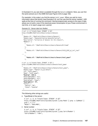
With this token, you now can receive data from the server. You start by requesting data of the
Redfish root with /Redfish/v1. You receive data with other branches in the Redfish tree; for
example, Chassis.
For more data, you can use the newly discovered odata.id field information
/Redfish/v1/Chassis, as shown in Example 2-2.
Example 2-2 Get chassis data from Redfish
#curl -s -k -H "X-Auth-Token: $TOKEN" -X GET https://${eBMC}/redfish/v1
{
"@odata.id": "/redfish/v1",
"@odata.type": "#ServiceRoot.v1_12_0.ServiceRoot",
"AccountService": {
"@odata.id": "/redfish/v1/AccountService"
},
"Cables": {
"@odata.id": "/redfish/v1/Cables"
},
"CertificateService": {
"@odata.id": "/redfish/v1/CertificateService"
},
"Chassis": {
"@odata.id": "/redfish/v1/Chassis"
},
# curl -k -H "X-Auth-Token: $TOKEN" -X GET https://${eBMC}/Redfish/v1/Chassis
{
"@odata.id": "/Redfish/v1/Chassis",
"@odata.type": "#ChassisCollection.ChassisCollection",
"Members": [
{
"@odata.id": "/Redfish/v1/Chassis/chassis"
}
],
"Members@odata.count": 1,
"Name": "Chassis Collection"
# curl -k -H "X-Auth-Token: $TOKEN" -X GET https://${eBMC}/Redfish/v1/Chassis/chassis
{
"@odata.id": "/Redfish/v1/Chassis/chassis",
"@odata.type": "#Chassis.v1_16_0.Chassis",
"Actions": {
...
"PCIeSlots": {
"@odata.id": "/Redfish/v1/Chassis/chassis/PCIeSlots"
},
...
"Sensors": {
"@odata.id": "/Redfish/v1/Chassis/chassis/Sensors"
},
...
Under Chassis, another chassis is available (with lower case c). We can now use the tree with
both; that is, /Redfish/v1/Chassis/chassis. After running the tool, you can see in
Example 2-2 PCIeSlots and Sensors are available as examples of other resources on the
server.](https://image.slidesharecdn.com/ibmpower10-230912025237-2589e74c/85/IBM-Power10-pdf-120-320.jpg)
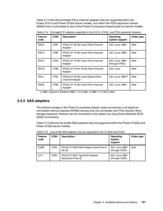
![Chapter 3. Available features and options 113
Table 3-5 Processor feature code specification for the Power 1022 server
Table 3-6 lists all processor-related feature codes for Power S1022 servers.
Table 3-6 Processor-related features of the Power S1022 server
Power S1024 processor feature codes
The Power S1024 provides two sockets to accommodate one or two Power10 DCMs. The
following DCM core densities are available:
12-core: Feature Code #EPGM
Processor
card
feature
code
Processor
module
type
Number
of cores
Typical
frequency
range
[GHz]
CUoDa
static
processor core
activation
Feature Code
Base processor
core activation
Feature Code for
Pools 2.0
Base core
activations
converted
from CUoD
static
activations
#EPG9 DCM 12 2.90 to 4.0 #EPF9 #EUCB #EUCH
#EPG8 DCM 16 2.75 to 4.0 #EPF8 #EUCA #EUCG
#EPGA DCM 20 2.45 to 3.9 #EPFA #EUCC #EUCJ
a. Capacity Upgrade on Demand
Feature Code Description
#EPG9 12-core typical 2.90 to 4.0 GHz (maximum) Power10 processor card, available in
quantity of one (1-socket configuration) or two (2-socket configuration)
#EPG8 16-core typical 2.75 to 4.0 GHz (maximum) Power10 processor card, available in
quantity of two (2-socket configuration) only
#EPGA 20-core typical 2.45 to 3.90 GHz (maximum) Power10 processor card, available in
quantity of two (2-socket configuration) only
#EPF9 One CUoD static processor core activation for #EPG9
#EPF8 One CUoD static processor core activation for #EPG8
#EPFA One CUoD static processor core activation for #EPGA
#2319 Factory deconfiguration of one core for #EPG9, #EPG8, or #EPGA
#EP20 Power Enterprise Pools 2.0 enablement
#EUCB One base processor core activation on processor card #EPG9 for Pools 2.0 to
support any operating system
#EUCA One base processor core activation on processor card #EPG8 for Pools 2.0 to
support any operating system
#EUCC One base processor core activation on processor card #EPGA for Pools 2.0 to
support any operating system
#EUCH One base processor core activation on processor card #EPG9 for Pools 2.0 to
support any operating system (converted from #EPF9)
#EUCG One base processor core activation on processor card #EPG8for Pools 2.0 to
support any operating system (converted from #EPF8)
#EUCJ One base processor core activation on processor card #EPGA for Pools 2.0 to
support any operating system (converted from #EPFA)](https://image.slidesharecdn.com/ibmpower10-230912025237-2589e74c/85/IBM-Power10-pdf-127-320.jpg)
![Chapter 3. Available features and options 115
Table 3-7 Processor feature code specification for the Power S1024 server
Table 3-8 lists all processor-related feature codes for Power S1024 servers.
Table 3-8 Processor-related features of the Power S1024 server
Processor
card
feature
code
Processor
module
type
Number
of cores
Typical
frequency
range
[GHz]
CUoD static
processor core
activation
Feature Code
Base processor
core activation
Feature Code for
Pools 2.0
Base core
activations
converted
from CUoD
static
activations
#EPGM DCM 12 3.40 - 4.0 #EPFM #EUBX #EUBZ
#EPGC DCM 16 3.10 - 4.0 #EPFC #EUCK #EUCR
#EPGD DCM 24 2.75 - 3.9 #EPFD #EUCS #EUCT
Feature code Description
#EPGM 12-core typical 3.40 to 4.0 GHz (maximum) Power10 processor card, available in
quantity of one (1-socket configuration) or two (2-socket configuration)
#EPGC 16-core typical 3.10 to 4.0 GHz (maximum) Power10 processor card, available in
quantity of two (2-socket configuration) only
#EPGD 24-core typical 2.75 to 3.9 GHz (maximum) Power10 processor card, available in
quantity of two (2-socket configuration) only
#EPFM One CUoD static processor core activation for #EPGM
#EPFC One CUoD static processor core activation for #EPGC
#EPFD One CUoD static processor core activation for #EPGD
#2319 Factory deconfiguration of one core for #EPGM, #EPGC, or #EPGD
#EP20 Power Enterprise Pools 2.0 enablement
#EUBX One base processor core activation on processor card #EPGM for Pools 2.0 to
support any operating system
#EUCK One base processor core activation on processor card #EPGC for Pools 2.0 to
support any operating system
#EUCL One base processor core activation on processor card #EPGD for Pools 2.0 to
support any operating system
#EUBZ One base processor core activation on processor card #EUGM for Pools 2.0 to
support any operating system converted from #EPFM
#EUCR One base processor core activation on processor card #EUGC for Pools 2.0 to
support any operating system converted from #EPFC
#EUCT One base processor core activation on processor card #EUGD for Pools 2.0 to
support any operating system converted from #EPFD](https://image.slidesharecdn.com/ibmpower10-230912025237-2589e74c/85/IBM-Power10-pdf-129-320.jpg)
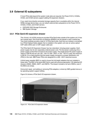
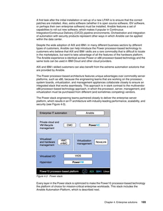
![Chapter 4. Enterprise solutions 157
Controls hardware I/O interrupt management facilities for LPARs.
Provides VLAN channels between LPARs that help reduce the need for physical Ethernet
adapters for inter-partition communication.
Monitors the enterprise baseboard management controller (eBMC) or the flexible service
processor (FSP) of the system and performs a reset or reload if it detects the loss of one
of the eBMC or FSP controllers, and notifies the operating system if the problem is not
corrected.
The Power Hypervisor is always active, regardless of the system configuration or whether it is
connected to the managed console. It requires memory to support the resource assignment
of the LPARs on the server.
The amount of memory that is required by the Power Hypervisor firmware varies according to
the following memory usage factors:
For hardware page tables (HPTs)
To support I/O devices
For virtualization
Memory usage for hardware page tables
Each partition on the system includes its own HPT that contributes to hypervisor memory
usage. The HPT is used by the operating system to translate from effective addresses to
physical real addresses in the hardware. This translation allows multiple operating systems to
run simultaneously in their own logical address space.
Whenever a virtual processor for a partition is dispatched on a physical processor, the
hypervisor indicates to the hardware the location of the partition HPT that can be used when
translating addresses.
The amount of memory for the HPT is based on the maximum memory size of the partition
and the HPT ratio. The default HPT ratio is 1/128th (for AIX, Virtual I/O Server [VIOS], and
Linux partitions) of the maximum memory size of the partition. AIX, VIOS, and Linux use
larger page sizes (16 and 64 KB) instead of the use of 4 KB pages.
The use of larger page sizes reduces the overall number of pages that must be tracked;
therefore, the overall size of the HPT can be reduced. For example, the HPT is 2 GB for an
AIX partition with a maximum memory size of 256 GB.
When defining a partition, the maximum memory size that is specified is based on the amount
of memory that can be dynamically added to the dynamic partition (DLPAR) without changing
the configuration and restarting the partition.
In addition to setting the maximum memory size, the HPT ratio can be configured. The
hpt_ratio parameter for the chsyscfg Hardware Management Console (HMC) command can
be issued to define the HPT ratio that is used for a partition profile. The following values are
valid:
1:32
1:64
1:128
1:256
1:512](https://image.slidesharecdn.com/ibmpower10-230912025237-2589e74c/85/IBM-Power10-pdf-171-320.jpg)