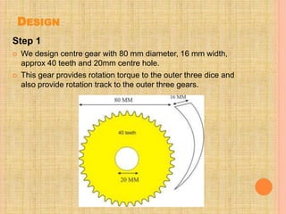
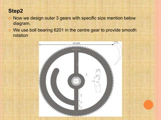
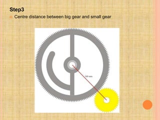
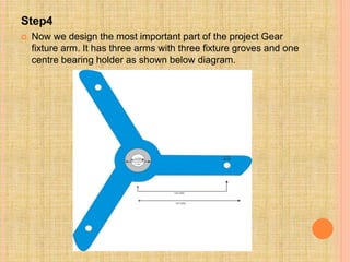
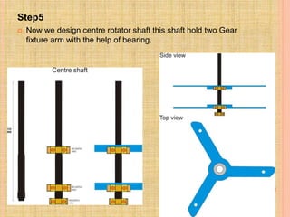
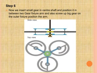
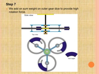
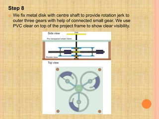
SEMI-PERPETUAL
MOTION
MACHINE
Harsh Gupta
M.Tech. (Automobile Engineering)
Amity School of Engineering and Technology
INTRODUCTION
What is perpetual motion?
Perpetual motion can be described as "motion that continues
indefinitely without any external source of energy; impossible
in practice because of friction."It can also be described as "the
motion of a hypothetical machine which, once activated, would
run forever unless subject to an external force or to wear".
There is a scientific consensus that perpetual motion in an
isolated system would violate the first and/or second law of
thermodynamics
WORKING PRINCIPLE
 There is a scientific consensus that perpetual
motion in an isolated system violates either the first
law of thermodynamics, the second law of
thermodynamics, or both. The first law of
thermodynamics is essentially a statement of
conservation of energy. The second law can be
phrased in several different ways, the most intuitive
of which is that heat flows spontaneously from
hotter to colder places and basically the above
mentioned project follows the second law of
thermodynamics and also works on the principle of
centripetal force.
WHAT IS CENTRIPETAL FORCE?
 Centripetal force (from Latin centrum "center" and
petere "to seek") is a force that makes a body
follow a curved path: it is always directed
orthogonaly to the velocity of the body, towards the
instantaneous center of curvature of the path. The
mathematical description was derived in 1659 by
Dutch physicist Christian Huygens. Isaac Newton's
description was: "A centripetal force is that by which
bodies are drawn or impelled or in any way tend,
towards a point as to a center."
MATHEMATICAL FORMULAE OF
CENTRIPETAL FORCE:-
 The magnitude of the centripetal force on an object of
mass m moving at a speed v along a path with radius of
curvature r is:
 Where ac is the centripetal acceleration. The direction of
the force is toward the center of the circle in which the
object is moving, or the osculating circle, the circle that
best fits the local path of the object, if the path is not
circular. This force is also sometimes written in terms of
the angular velocity ω of the object about the center of
the circle:
 Expressed using the period for one revolution of the
circle, T, the equation becomes:
COMPONENTS USED
 Casting gears
 Iron shaft
 Bearings
 PVC clear sheet
 Screws
 Nails
 Wooden frame
 Dynamo meter
 Alluminium pulley
DESIGN
Step 1
 We design centre gear with 80 mm diameter, 16 mm width,
approx 40 teeth and 20mm centre hole.
 This gear provides rotation torque to the outer three dice and
also provide rotation track to the outer three gears.
Step2
 Now we design outer 3 gears with specific size mention below
diagram.
 We use boll bearing 6201 in the centre gear to provide smooth
rotation
Step3
 Centre distance between big gear and small gear
Step4
 Now we design the most important part of the project Gear
fixture arm. It has three arms with three fixture groves and one
centre bearing holder as shown below diagram.
Step5
 Now we design centre rotator shaft this shaft hold two Gear
fixture arm with the help of bearing.
Step 6
 Now we insert small gear in centre shaft and position it in
between two Gear fixture arm and also screw up big gear on
the outer fixture position the arm.
Step 7
 We add on sum weight on outer gear dice to provide high
rotation force.
Step 8
 We fix metal disk with centre shaft to provide rotation jerk to
outer three gears with help of connected small gear. We use
PVC clear on top of the project frame to show clear visibility.
PROBLEMS FACED
 Avaliability of components of desired specification
in market as per the design.
 To vary the output speed.
 Balancing of gears and vibrations.
SOLUTIONS ADAPTED
 As per the market survey conducted by us we have
selected the components with nearest possible
specifications as per our design to get the desired
power.
 Output speed is controlled by less input manual
power
 By attaching masses on each gear,balancing is
obtained.
ADVANTAGES
 Zero fuel cost(the cost is involved only in the
arrangement of gears).
 More power output.
DISADVANTAGES
 Vibration of mechanical parts
 Risk of jerk while operating manually
FUTURE SCOPE
 Our project basically means “ higher generation of
power with smaller input” which can be used in
agriculture fields as during the time of draughts a
huge amount of water supply is needed so at that
time this machine will help in generating maximum
pumping power without any extra amount of energy.
THANK YOU

Semi Perpetual Motion Machine(ppt)

  • 1.
    SEMI-PERPETUAL MOTION MACHINE Harsh Gupta M.Tech. (AutomobileEngineering) Amity School of Engineering and Technology
  • 2.
    INTRODUCTION What is perpetualmotion? Perpetual motion can be described as "motion that continues indefinitely without any external source of energy; impossible in practice because of friction."It can also be described as "the motion of a hypothetical machine which, once activated, would run forever unless subject to an external force or to wear". There is a scientific consensus that perpetual motion in an isolated system would violate the first and/or second law of thermodynamics
  • 3.
    WORKING PRINCIPLE  Thereis a scientific consensus that perpetual motion in an isolated system violates either the first law of thermodynamics, the second law of thermodynamics, or both. The first law of thermodynamics is essentially a statement of conservation of energy. The second law can be phrased in several different ways, the most intuitive of which is that heat flows spontaneously from hotter to colder places and basically the above mentioned project follows the second law of thermodynamics and also works on the principle of centripetal force.
  • 4.
    WHAT IS CENTRIPETALFORCE?  Centripetal force (from Latin centrum "center" and petere "to seek") is a force that makes a body follow a curved path: it is always directed orthogonaly to the velocity of the body, towards the instantaneous center of curvature of the path. The mathematical description was derived in 1659 by Dutch physicist Christian Huygens. Isaac Newton's description was: "A centripetal force is that by which bodies are drawn or impelled or in any way tend, towards a point as to a center."
  • 5.
    MATHEMATICAL FORMULAE OF CENTRIPETALFORCE:-  The magnitude of the centripetal force on an object of mass m moving at a speed v along a path with radius of curvature r is:  Where ac is the centripetal acceleration. The direction of the force is toward the center of the circle in which the object is moving, or the osculating circle, the circle that best fits the local path of the object, if the path is not circular. This force is also sometimes written in terms of the angular velocity ω of the object about the center of the circle:
  • 6.
     Expressed usingthe period for one revolution of the circle, T, the equation becomes:
  • 7.
    COMPONENTS USED  Castinggears  Iron shaft  Bearings  PVC clear sheet  Screws  Nails  Wooden frame  Dynamo meter  Alluminium pulley
  • 8.
    DESIGN Step 1  Wedesign centre gear with 80 mm diameter, 16 mm width, approx 40 teeth and 20mm centre hole.  This gear provides rotation torque to the outer three dice and also provide rotation track to the outer three gears.
  • 9.
    Step2  Now wedesign outer 3 gears with specific size mention below diagram.  We use boll bearing 6201 in the centre gear to provide smooth rotation
  • 10.
    Step3  Centre distancebetween big gear and small gear
  • 11.
    Step4  Now wedesign the most important part of the project Gear fixture arm. It has three arms with three fixture groves and one centre bearing holder as shown below diagram.
  • 12.
    Step5  Now wedesign centre rotator shaft this shaft hold two Gear fixture arm with the help of bearing.
  • 13.
    Step 6  Nowwe insert small gear in centre shaft and position it in between two Gear fixture arm and also screw up big gear on the outer fixture position the arm.
  • 14.
    Step 7  Weadd on sum weight on outer gear dice to provide high rotation force.
  • 15.
    Step 8  Wefix metal disk with centre shaft to provide rotation jerk to outer three gears with help of connected small gear. We use PVC clear on top of the project frame to show clear visibility.
  • 16.
    PROBLEMS FACED  Avaliabilityof components of desired specification in market as per the design.  To vary the output speed.  Balancing of gears and vibrations.
  • 17.
    SOLUTIONS ADAPTED  Asper the market survey conducted by us we have selected the components with nearest possible specifications as per our design to get the desired power.  Output speed is controlled by less input manual power  By attaching masses on each gear,balancing is obtained.
  • 18.
    ADVANTAGES  Zero fuelcost(the cost is involved only in the arrangement of gears).  More power output. DISADVANTAGES  Vibration of mechanical parts  Risk of jerk while operating manually
  • 19.
    FUTURE SCOPE  Ourproject basically means “ higher generation of power with smaller input” which can be used in agriculture fields as during the time of draughts a huge amount of water supply is needed so at that time this machine will help in generating maximum pumping power without any extra amount of energy.
  • 20.