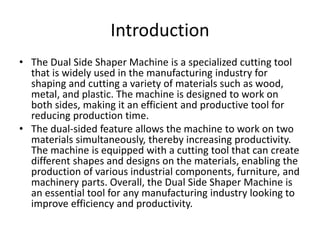
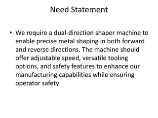
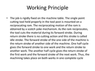
VISVESVARAYA TECHNOLOGICAL UNIVERSITY
BELAGAVI – 590018
“Fabrication of A Dual Side Shaping Machine for Industrial Applications”
Project Team
S l. No Name of Student USN
1 Sandeep Jainapur 2KL20ME026
2 Ajit K Maragali 2KL21ME406
3 Akash Yaranal 2KL21ME407
4 Sanket Nirmale 2KL21ME472
Under the Guidance of : Dr D. C. Patil
Content
• Introduction
• Literature Survey
• Need Statement
• Working Principle
• Methodology
• Design Calculations
• Time line and Budget
• References
• Conclusion
Introduction
• The Dual Side Shaper Machine is a specialized cutting tool
that is widely used in the manufacturing industry for
shaping and cutting a variety of materials such as wood,
metal, and plastic. The machine is designed to work on
both sides, making it an efficient and productive tool for
reducing production time.
• The dual-sided feature allows the machine to work on two
materials simultaneously, thereby increasing productivity.
The machine is equipped with a cutting tool that can create
different shapes and designs on the materials, enabling the
production of various industrial components, furniture, and
machinery parts. Overall, the Dual Side Shaper Machine is
an essential tool for any manufacturing industry looking to
improve efficiency and productivity.
Literature Survey
R M Lathe Volume8Issue2,August-2013
• His Investigation revealed issues with conventional machining, including high time
consumption and increased labor costs.
• To address these challenges, he implemented automated electric pneumatic
devices and PLCs in shaper machines.
M.V.N. Srujan Manohar Volume1Issue6 August-2012
• He explores the use of a pneumatic shaper for high production of automatic gear
cutting with auto-indexing.
• Power for the operation was sourced from pneumatic systems, and control
accessories were employed to drive the ram or cylinder piston for achieving both
forward and return strokes.
R. Maguteeswaran International Journal of Research In Aeronautical and Mechanical
Engineering, Volume 2, Feb- 2014.
• He noted that machining processes were typically performed by separate
machining machines, leading to increased space requirements, time consumption,
and higher expenses.
• To address these challenges, he developed a multi-operation machine capable of
performing three operations in a single unit: drilling, slotting, and shaping.
R. K. Tyagi, M. Verma, and Sukanya Borah, JECET;
• September-November, 2012; Vol.1. No.3, 372-380. Dynamic analysis of shaper machine
mechanism by Software is one of the prominent techniques for force, torque, velocity,
acceleration with a variety of time vital for industrial applications i.e., failure and life analysis.
• In This article, stab has been made to assess dynamic analysis for shaper machine Components
and cutting tool which would work on the principle of quick return Mechanism, and suitable for
a wide range of materials for metal cutting. Statistical Exploration with the help of MSC ADAM
software on machine components is Systemically investigated by means of time variation.
Frankfurt-am Main, 10 January 2011.:
• The crisis is over, but selling machinery remains a tough business. Machine tools nowadays have
to be veritable “jack of all trades”, able to handle all kinds of materials, to manage without any
process materials as far as possible,
• It is capable of adapting to new job profiles with maximized flexibility. Two highly respected
experts on machining and forming from Dortmund and Chemnitz report on what’s in store for
machine tool manufacturers and users.
Need Statement
• We require a dual-direction shaper machine to
enable precise metal shaping in both forward
and reverse directions. The machine should
offer adjustable speed, versatile tooling
options, and safety features to enhance our
manufacturing capabilities while ensuring
operator safety
Working Principle
• The job is rigidly fixed on the machine table. The single point
cutting tool held properly in the tool post is mounted on a
reciprocating ram. The reciprocating motion of the ram is
obtained by a scotch yoke mechanism. As the ram reciprocates,
the tool cuts the material during its forward stroke. During
return stroke there is no cutting action and this stroke is called
idle stroke. The forward stroke of the one side of the machine is
the return stroke of another side of the machine. One half cycle
gives the forward stroke to one work and the return stroke to
another work. The another half cycle gives the return stroke of
the first work and the forward stroke of the next work. Thus, the
machining takes place on both works in one complete cycle
Methodology
Literature Survey
Concept Evaluation and Concept selection
Design calculations
Components selecting or purchasing
Fabrication and Assembly
Testing
Prototype
3D Model
Design calculations
Specifications
Power = 736 watt
Speed = 1440 rpm
Diameter of crank = 450mm
Length of slotted bar = 460mm
Length of connecting rod = 800
Preferring of Pulley diameter:
Power given selected small pulley of dia. (d) = 80mm (From design data handbook table 14.8)
V-belt is used in the power transformation hence using dia. ratio to calculate larger pulley speed.
Dia. ratio = D_ = _n_
d N
350_ = 1440_ (Assume D= 350 mm)
80 N
N = 350 rpm
Therefore larger pulley speed (N) = 350rpm.
Design of shaft
Diameter of Shaft = 30mm
Permissible shear stress for mild steel = 34 N/mm2
Shear Stress, Ʈ = _16T_
πd3
T=?
T = _P × 60_ = 20.08 × 10³ N-mm
2 ×π×n
Ʈ = _16 × 20.08_
π × 0.033
3.78 N/mm2 < Ʈ Permissible
Therefore design is safe.
V Belt design
Taking Center distance as 1100mm
Length of belt
L = 2C + [π /2(D+d)] + [(D-d)/4C]
L = 2200mm
Groove angle
α = 180- [(D-d)/C] × 60
α = 165.27°
Cutting force
Torque = force × Radius of Crank
T = F × 225
F= 163.33 N
3D Model
Work done so far
• Referred journal papers
• Concept evaluation
• Design calculation
• 3D modeling
• Selection of components
Project time line
Oct-2023 Nov-2023 Dec-2023 Jan-2024 Feb-2024 March-2024
Modelling
& Design
Purchasing
Fabrication
Assembly
Testing
Final
Submission
Approximate budget of the project: Rs 13000 /-
Conclusion
• In the proposed project work a dual side shaper will be
designed and fabricated. The dual side shaper machine
is used to manufacture components similar to a
standard shaper machine. The machining time required
for this dual shaper is less as compared to the normal
shaper. Hence, the production rate is increased. The
designed dual shaper has been used for only trial
production. In the future, it would be used for
commercial production in industries. The double side
shaper apparatus looks like amassing of two existing
shaper machines. Subsequently, the machine
consumes less space, the number of gears is
diminished.
References
[1]. R M Lathe, International Journal of Engineering Research
and Development (IJERD), Volume8Issue2,August-2013.
[2]. M.V.N. Srujan Manohar, International Journal of
Engineering Research and Technology (IJERT),Volume1Issue6
August-2012.
[3]. S. Ravindran, Middle-east Journal of Scientific Research,
12(12): 1710-1714, 2012.
[4]. Khurmi, R.S, and Gupta, J.K.(1997) 'A TEXTBOOK OF
MACHINE DESIGN', S. Chand Publications, New Delhi, India

Both side Shaper machine with calculation.pptx

  • 1.
    VISVESVARAYA TECHNOLOGICAL UNIVERSITY BELAGAVI– 590018 “Fabrication of A Dual Side Shaping Machine for Industrial Applications” Project Team S l. No Name of Student USN 1 Sandeep Jainapur 2KL20ME026 2 Ajit K Maragali 2KL21ME406 3 Akash Yaranal 2KL21ME407 4 Sanket Nirmale 2KL21ME472 Under the Guidance of : Dr D. C. Patil
  • 2.
    Content • Introduction • LiteratureSurvey • Need Statement • Working Principle • Methodology • Design Calculations • Time line and Budget • References • Conclusion
  • 3.
    Introduction • The DualSide Shaper Machine is a specialized cutting tool that is widely used in the manufacturing industry for shaping and cutting a variety of materials such as wood, metal, and plastic. The machine is designed to work on both sides, making it an efficient and productive tool for reducing production time. • The dual-sided feature allows the machine to work on two materials simultaneously, thereby increasing productivity. The machine is equipped with a cutting tool that can create different shapes and designs on the materials, enabling the production of various industrial components, furniture, and machinery parts. Overall, the Dual Side Shaper Machine is an essential tool for any manufacturing industry looking to improve efficiency and productivity.
  • 4.
    Literature Survey R MLathe Volume8Issue2,August-2013 • His Investigation revealed issues with conventional machining, including high time consumption and increased labor costs. • To address these challenges, he implemented automated electric pneumatic devices and PLCs in shaper machines. M.V.N. Srujan Manohar Volume1Issue6 August-2012 • He explores the use of a pneumatic shaper for high production of automatic gear cutting with auto-indexing. • Power for the operation was sourced from pneumatic systems, and control accessories were employed to drive the ram or cylinder piston for achieving both forward and return strokes. R. Maguteeswaran International Journal of Research In Aeronautical and Mechanical Engineering, Volume 2, Feb- 2014. • He noted that machining processes were typically performed by separate machining machines, leading to increased space requirements, time consumption, and higher expenses. • To address these challenges, he developed a multi-operation machine capable of performing three operations in a single unit: drilling, slotting, and shaping.
  • 5.
    R. K. Tyagi,M. Verma, and Sukanya Borah, JECET; • September-November, 2012; Vol.1. No.3, 372-380. Dynamic analysis of shaper machine mechanism by Software is one of the prominent techniques for force, torque, velocity, acceleration with a variety of time vital for industrial applications i.e., failure and life analysis. • In This article, stab has been made to assess dynamic analysis for shaper machine Components and cutting tool which would work on the principle of quick return Mechanism, and suitable for a wide range of materials for metal cutting. Statistical Exploration with the help of MSC ADAM software on machine components is Systemically investigated by means of time variation. Frankfurt-am Main, 10 January 2011.: • The crisis is over, but selling machinery remains a tough business. Machine tools nowadays have to be veritable “jack of all trades”, able to handle all kinds of materials, to manage without any process materials as far as possible, • It is capable of adapting to new job profiles with maximized flexibility. Two highly respected experts on machining and forming from Dortmund and Chemnitz report on what’s in store for machine tool manufacturers and users.
  • 6.
    Need Statement • Werequire a dual-direction shaper machine to enable precise metal shaping in both forward and reverse directions. The machine should offer adjustable speed, versatile tooling options, and safety features to enhance our manufacturing capabilities while ensuring operator safety
  • 7.
    Working Principle • Thejob is rigidly fixed on the machine table. The single point cutting tool held properly in the tool post is mounted on a reciprocating ram. The reciprocating motion of the ram is obtained by a scotch yoke mechanism. As the ram reciprocates, the tool cuts the material during its forward stroke. During return stroke there is no cutting action and this stroke is called idle stroke. The forward stroke of the one side of the machine is the return stroke of another side of the machine. One half cycle gives the forward stroke to one work and the return stroke to another work. The another half cycle gives the return stroke of the first work and the forward stroke of the next work. Thus, the machining takes place on both works in one complete cycle
  • 8.
    Methodology Literature Survey Concept Evaluationand Concept selection Design calculations Components selecting or purchasing Fabrication and Assembly Testing Prototype 3D Model
  • 9.
    Design calculations Specifications Power =736 watt Speed = 1440 rpm Diameter of crank = 450mm Length of slotted bar = 460mm Length of connecting rod = 800 Preferring of Pulley diameter: Power given selected small pulley of dia. (d) = 80mm (From design data handbook table 14.8) V-belt is used in the power transformation hence using dia. ratio to calculate larger pulley speed. Dia. ratio = D_ = _n_ d N 350_ = 1440_ (Assume D= 350 mm) 80 N N = 350 rpm Therefore larger pulley speed (N) = 350rpm.
  • 10.
    Design of shaft Diameterof Shaft = 30mm Permissible shear stress for mild steel = 34 N/mm2 Shear Stress, Ʈ = _16T_ πd3 T=? T = _P × 60_ = 20.08 × 10³ N-mm 2 ×π×n Ʈ = _16 × 20.08_ π × 0.033 3.78 N/mm2 < Ʈ Permissible Therefore design is safe. V Belt design Taking Center distance as 1100mm Length of belt L = 2C + [π /2(D+d)] + [(D-d)/4C] L = 2200mm
  • 11.
    Groove angle α =180- [(D-d)/C] × 60 α = 165.27° Cutting force Torque = force × Radius of Crank T = F × 225 F= 163.33 N
  • 12.
  • 14.
    Work done sofar • Referred journal papers • Concept evaluation • Design calculation • 3D modeling • Selection of components
  • 15.
    Project time line Oct-2023Nov-2023 Dec-2023 Jan-2024 Feb-2024 March-2024 Modelling & Design Purchasing Fabrication Assembly Testing Final Submission Approximate budget of the project: Rs 13000 /-
  • 16.
    Conclusion • In theproposed project work a dual side shaper will be designed and fabricated. The dual side shaper machine is used to manufacture components similar to a standard shaper machine. The machining time required for this dual shaper is less as compared to the normal shaper. Hence, the production rate is increased. The designed dual shaper has been used for only trial production. In the future, it would be used for commercial production in industries. The double side shaper apparatus looks like amassing of two existing shaper machines. Subsequently, the machine consumes less space, the number of gears is diminished.
  • 17.
    References [1]. R MLathe, International Journal of Engineering Research and Development (IJERD), Volume8Issue2,August-2013. [2]. M.V.N. Srujan Manohar, International Journal of Engineering Research and Technology (IJERT),Volume1Issue6 August-2012. [3]. S. Ravindran, Middle-east Journal of Scientific Research, 12(12): 1710-1714, 2012. [4]. Khurmi, R.S, and Gupta, J.K.(1997) 'A TEXTBOOK OF MACHINE DESIGN', S. Chand Publications, New Delhi, India