Download to read offline
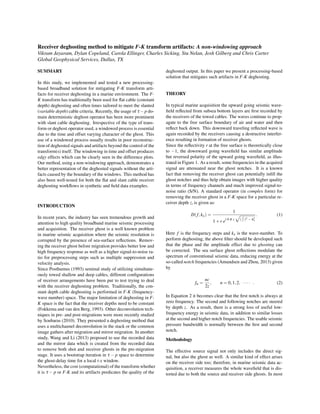
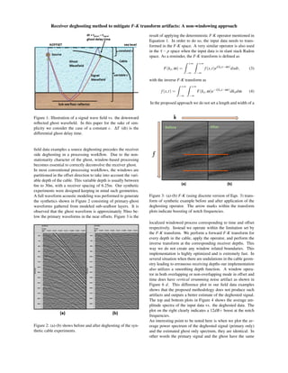
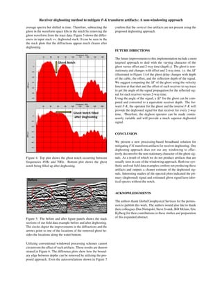
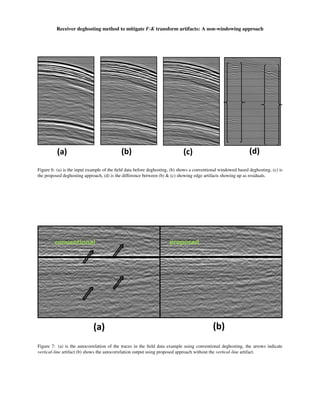

This study proposes a novel non-windowing receiver deghosting method to mitigate f-k transform artifacts in marine seismic data, offering improved representation of deghosted signals without the edge effects associated with windowed processes. The method has been tested on both flat and slant cable workflows, demonstrating better quality in frequency response and signal-to-noise ratio compared to traditional techniques. Results show that our approach effectively reduces artifacts and provides cleaner estimates of deghosted signals, supported by synthetic and field data examples.


