Download as PDF, PPTX

![Dept. of CE, GCE Kannur Dr.RajeshKN
Columns
• A ‘compression member’ is a structural element which is subjected
(predominantly) to axial compressive forces.
• Compression members are most commonly encountered in
reinforced concrete buildings as columns
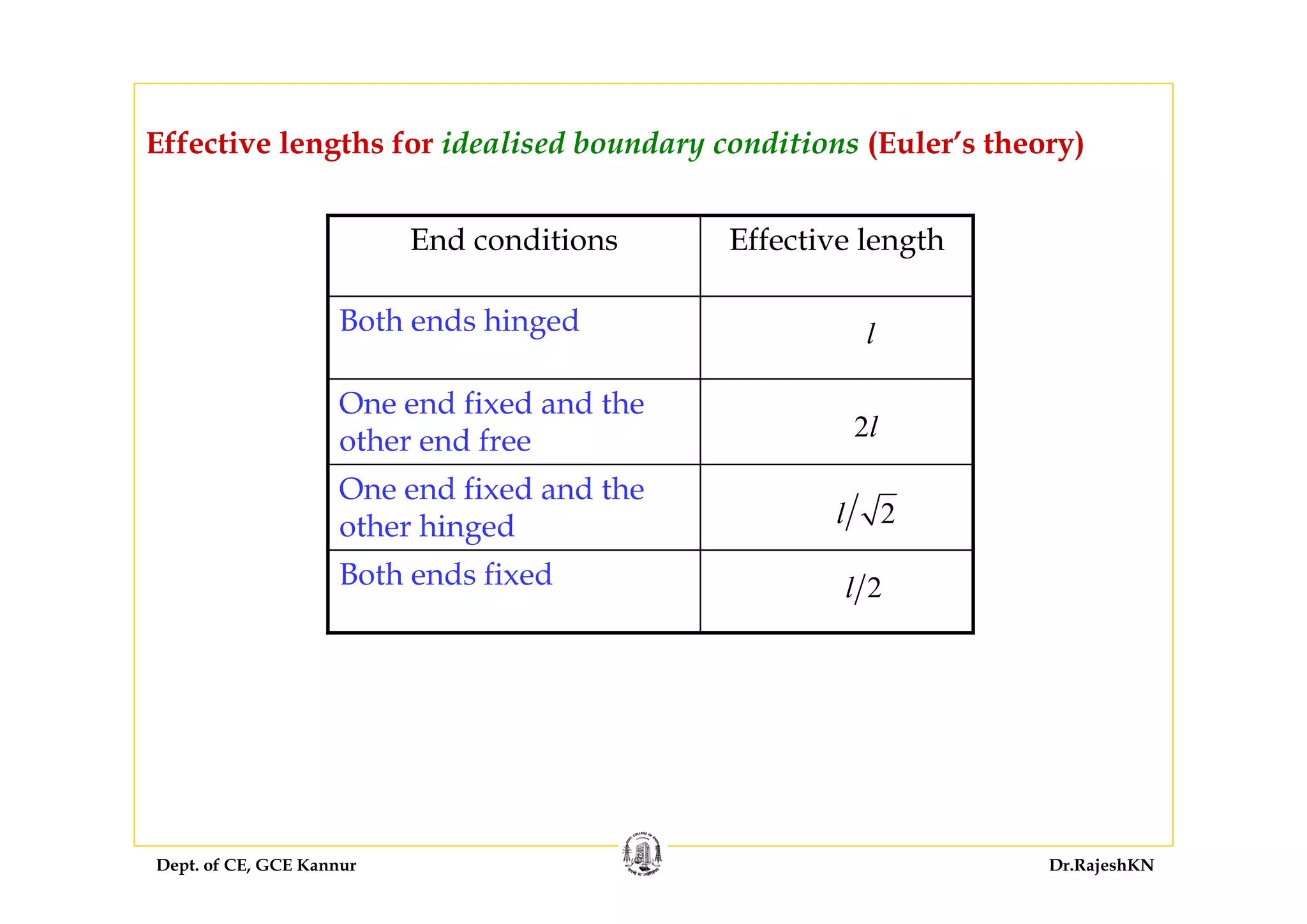
• Column is a compression member, the ‘effective length’ of which
exceeds three times the least lateral dimension (Cl. 25.1.1)
• ‘Pedestal’ is a vertical compression member whose ‘effective length’
is less than three times its least lateral dimension [Cl. 26.5.3.1(h)].](https://image.slidesharecdn.com/sd-i-module4-rajeshsir-140806050206-phpapp02/75/Sd-i-module4-rajesh-sir-4-2048.jpg)
![Dept. of CE, GCE Kannur Dr.RajeshKN
Assume longitudinal reinforcement percentage as 3.5%.
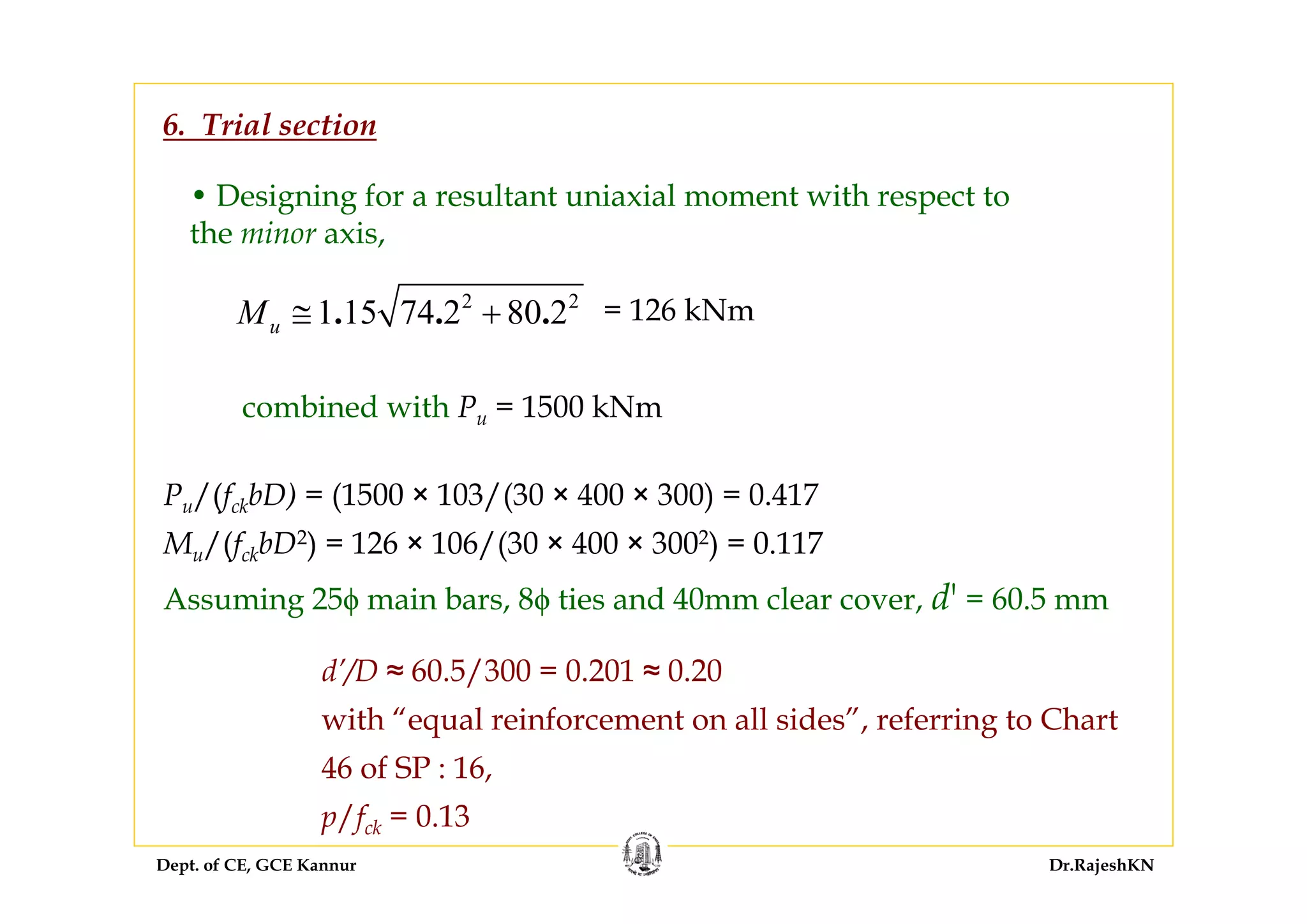
Designing for uniaxial eccentricity with Pu = 1300 kN and
3. Trial section: Longitudinal reinforcement
As,reqd = 3.5 × 4002/100 = 5600 mm2
Provide 12 – 25 dia: As = 491 × 12 = 5892 mm2 > 5600 mm2. The
arrangement of bars is shown in Figure??.
Uniaxial moment capacities: Mux1, Muy1 [Here, due to symmetry, Mux1
= Mux2]
= 0.325
u
ck
P
f bd](https://image.slidesharecdn.com/sd-i-module4-rajeshsir-140806050206-phpapp02/75/Sd-i-module4-rajesh-sir-40-2048.jpg)
![Dept. of CE, GCE Kannur Dr.RajeshKN
→ preqd = 0.13 × 30 = 3.9
→ As,reqd = 3.9 × 300 × 400/100 = 4680 mm2
Provide 8–28 ϕ [As = 8 × 616 mm2] 4928 > 4680
→ pprovided = 4928 × 100/(300 × 400) =4.107
→ p/fck = 4.107/30 = 0.137](https://image.slidesharecdn.com/sd-i-module4-rajeshsir-140806050206-phpapp02/75/Sd-i-module4-rajesh-sir-69-2048.jpg)

![Dept. of CE, GCE Kannur Dr.RajeshKN
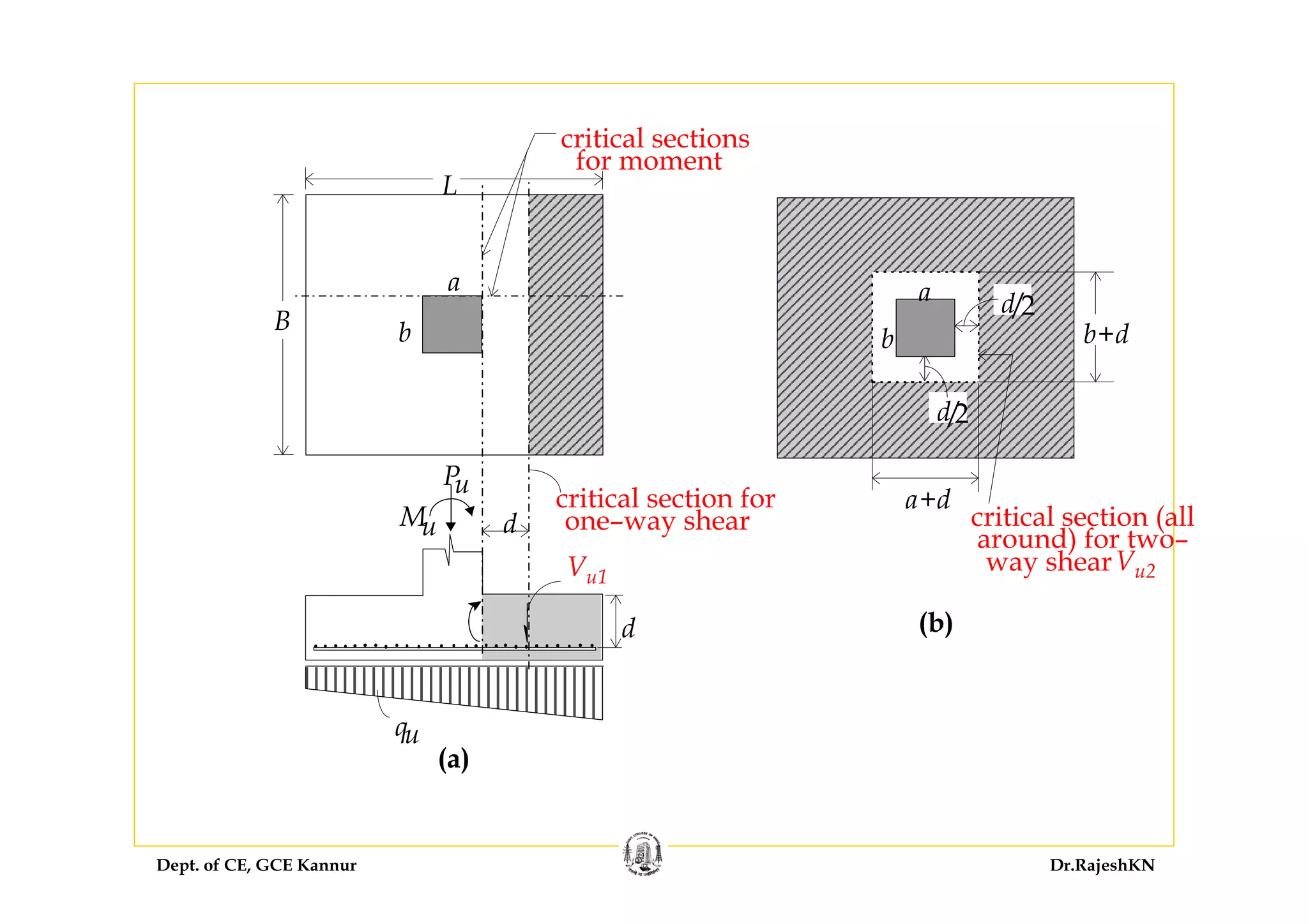
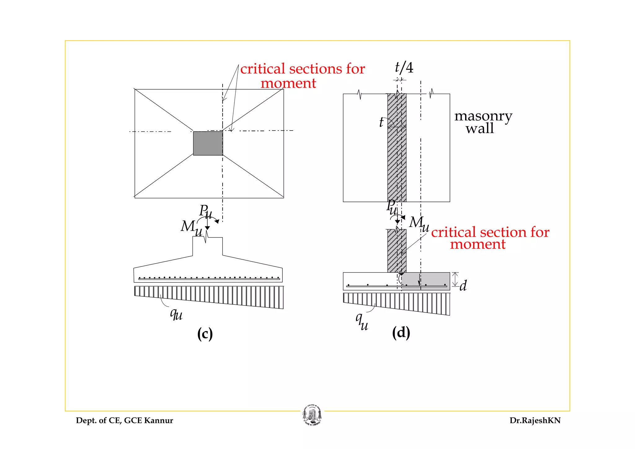
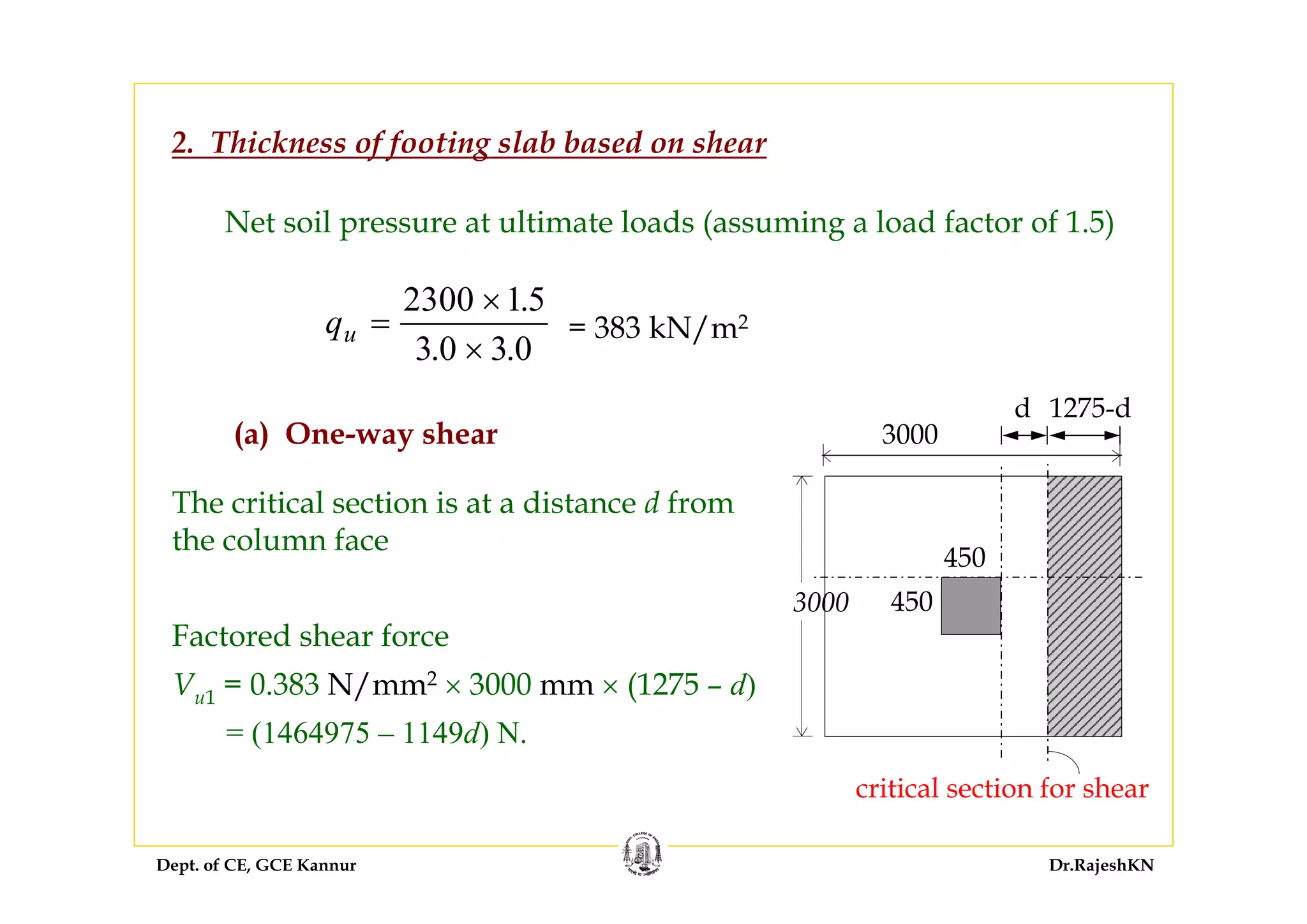
Thickness of Footing Base Slab
• The thickness of a footing base slab is generally based on
considerations of shear and flexure, which are critical near the
column location.
• Generally, shear considerations predominate, and the thickness is
based on shear criteria.
Both one-way shear and two-way shear (‘punching shear’) need to
be considered [Cl. 34.2.4.1].](https://image.slidesharecdn.com/sd-i-module4-rajeshsir-140806050206-phpapp02/75/Sd-i-module4-rajesh-sir-86-2048.jpg)
![Dept. of CE, GCE Kannur Dr.RajeshKN
Assuming 0 36 MPa.cτ =
(for M 20 concrete with, say, pt = 0.25) [Table 19],
One-way shear resistance Vc1 = 0.36 × 3000 × d = (1080d) N
Vu1 ≤ Vc1
1464975 – 1149d ≤ 1080d
d ≥ 658 mm](https://image.slidesharecdn.com/sd-i-module4-rajeshsir-140806050206-phpapp02/75/Sd-i-module4-rajesh-sir-92-2048.jpg)
![Dept. of CE, GCE Kannur Dr.RajeshKN
(b) Two-way shear
The critical section is at d/2 from the periphery of the column
⇒ Factored shear force Vu2 = 0.383 × [30002 – (450 + d)2]
Two-way shear resistance
( )2 4 450c s cV k d dτ ⎡ ⎤= × × +⎣ ⎦
where ks = 1.0 for a square column
0 25 20.cτ =
= 1.118 MPa (Cl. 31.6.3.1)
450
450
d/2
d/2
critical section (all
around) for two–
way shear Vu2
450+d
450+d](https://image.slidesharecdn.com/sd-i-module4-rajeshsir-140806050206-phpapp02/75/Sd-i-module4-rajesh-sir-93-2048.jpg)
![Dept. of CE, GCE Kannur Dr.RajeshKN
Vc2 = 1.0 × 1.118 × 4d (450 + d)
= (2012.4d + 4.472d2) N
Evidently, in this problem, one-way shear governs the thickness.
Assuming a clear cover of 75 mm and 16 φ bars in both directions,
with an average d = 658 mm,
thickness D ≥ 658 + 75 + 16 = 749 mm
Vu2 ≤ Vc2 ⇒ 0.383 × [30002 – (450 + d)2] ≤ 2012.4d + 4.472d2
3369442.5 - 0.383 d2 - 900d ≤ 2012.4d + 4.472d2
4.855 d2 + 2912.4 d - 3369442.5 ≥ 0
d ≥ 585.5](https://image.slidesharecdn.com/sd-i-module4-rajeshsir-140806050206-phpapp02/75/Sd-i-module4-rajesh-sir-94-2048.jpg)
![Dept. of CE, GCE Kannur Dr.RajeshKN
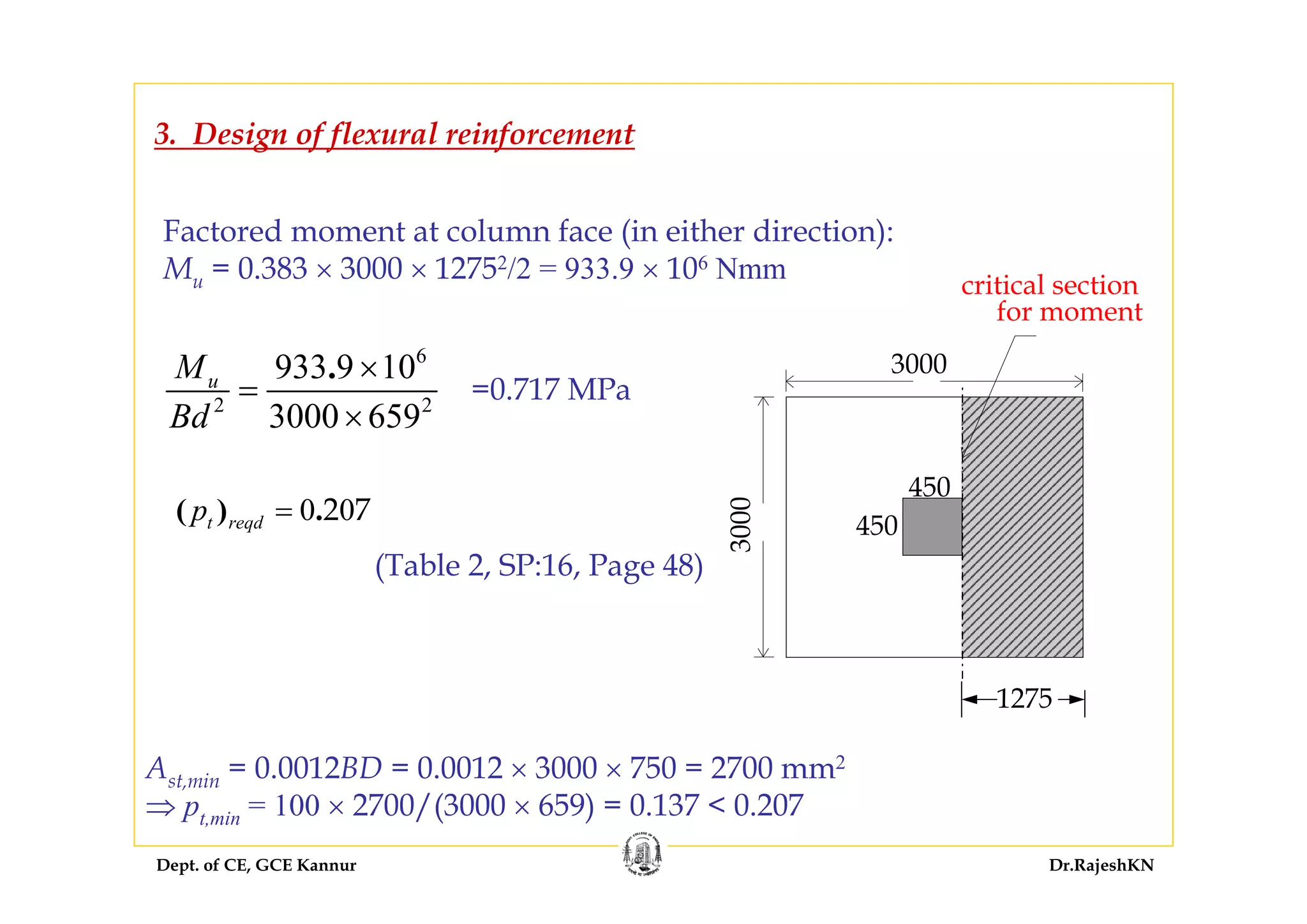
But this reinforcement is less than the 0.25% assumed for one-way shear.
Hence Ast,reqd = 0.25 × 3000 × 659/100 = 4943 mm2
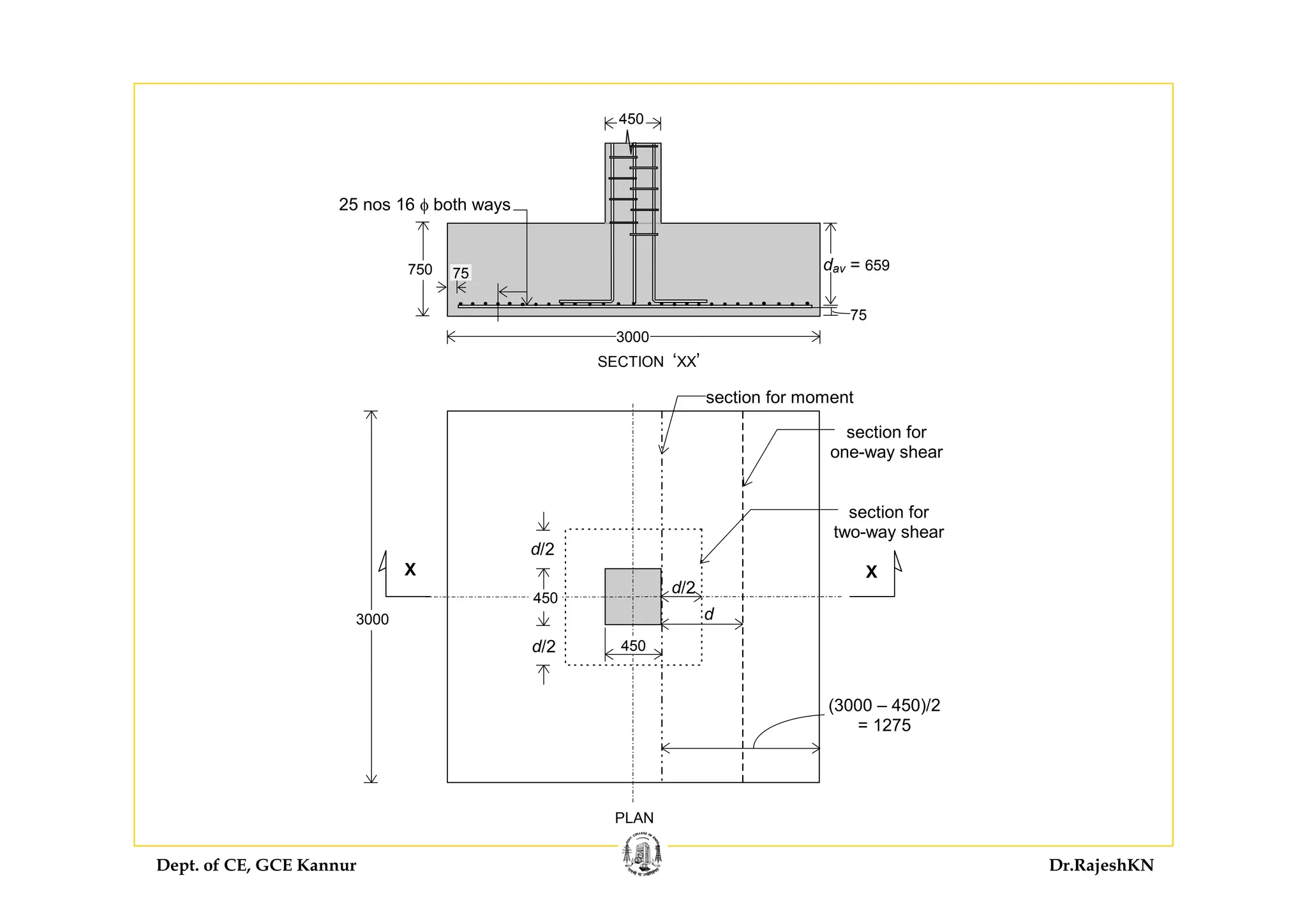
Using 16 mm φ bars, number of bars required = 4943/201 = 25
[corresponding spacing s = {3000 – (75 × 2) – 16}/(25 –1) = 118 mm —
is acceptable.]
Provide 25 nos 16 φ bars both ways
Required development length
( )0 87
4
. y
d
bd
f
L
φ
τ
= Cl. 26.2.1
For M 20 concrete and Fe 415 steel,
0 87 415
47
4 1 2 1 6
.
. .
dL φ φ
×
= =
× ×
For 16 φ bars in footing, Ld = 47.0 × 16 = 752 mm
Length available = 1275 – 75 = 1200 mm > 752 mm — Hence, OK.](https://image.slidesharecdn.com/sd-i-module4-rajeshsir-140806050206-phpapp02/75/Sd-i-module4-rajesh-sir-97-2048.jpg)

The document discusses the design of columns and footings in concrete structures. It covers various topics related to column design including classification of columns based on type of reinforcement, loading, and slenderness ratios. Short columns subjected to axial loads with or without eccentricity are analyzed. Design aspects such as effective length, minimum reinforcement requirements, cover and transverse tie spacing are described based on code specifications. Equations for equilibrium of uniformly loaded short columns are also presented.