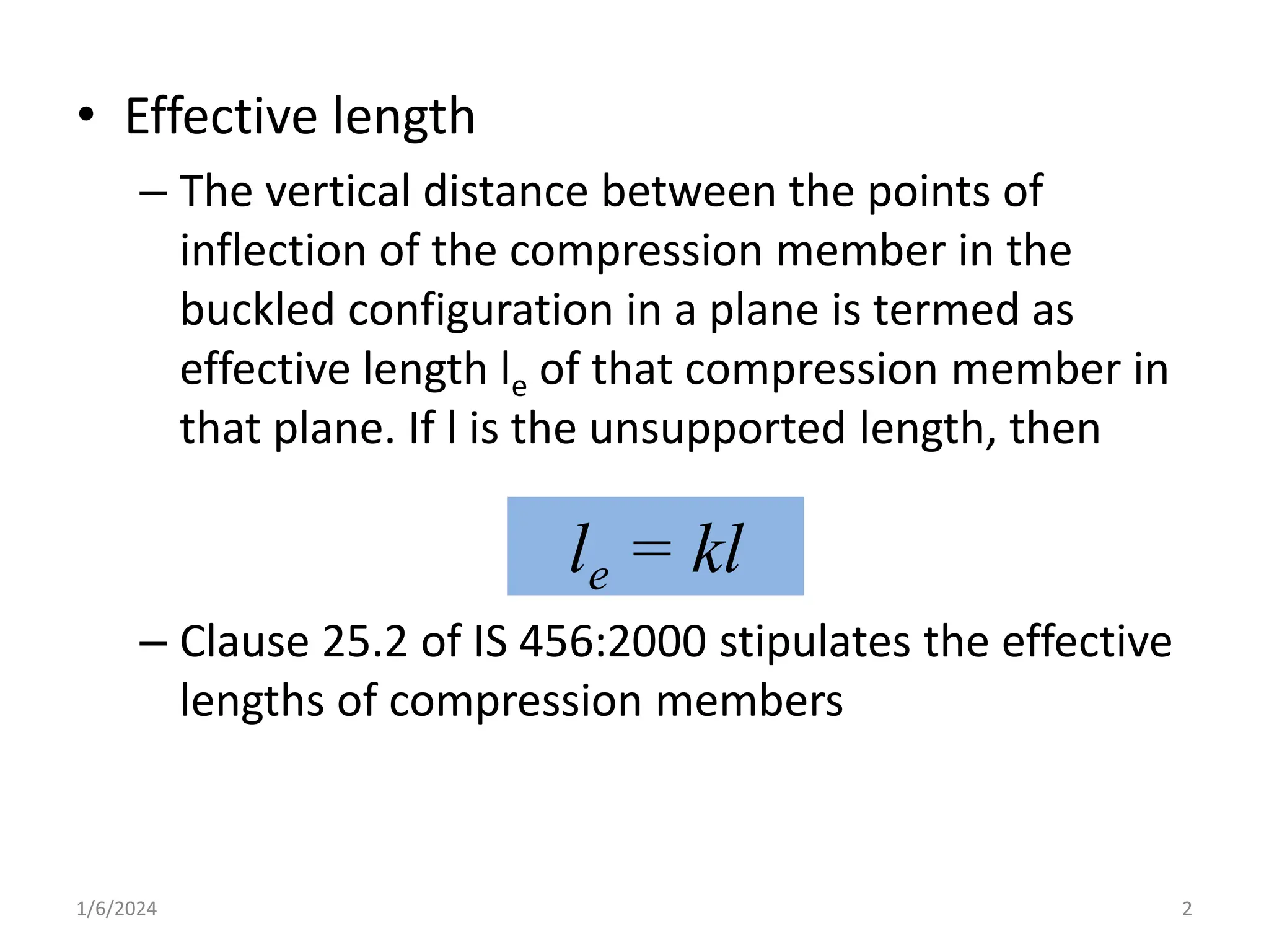
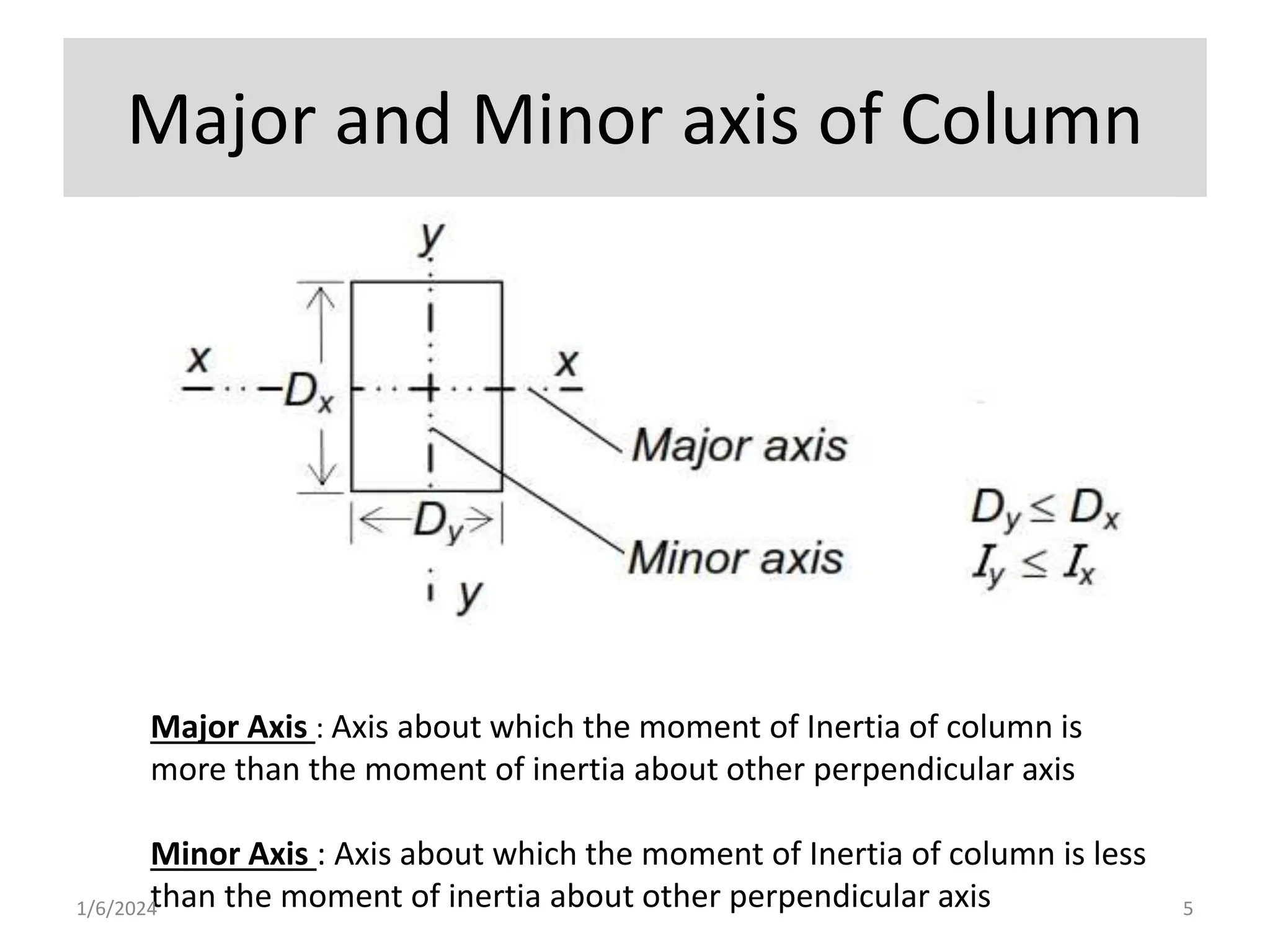
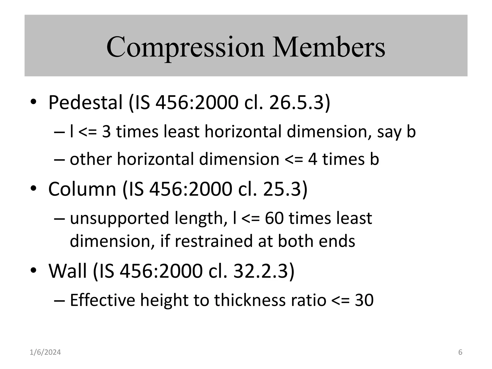
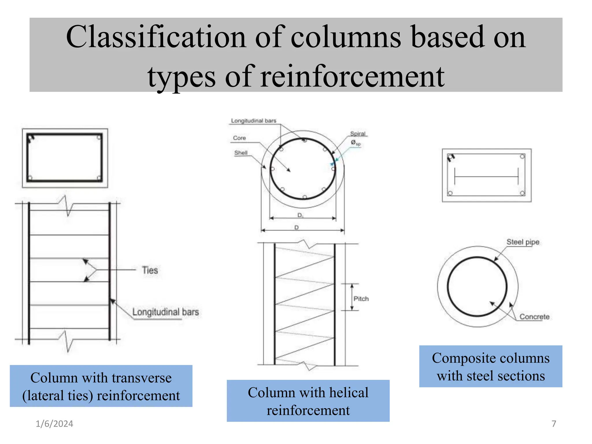
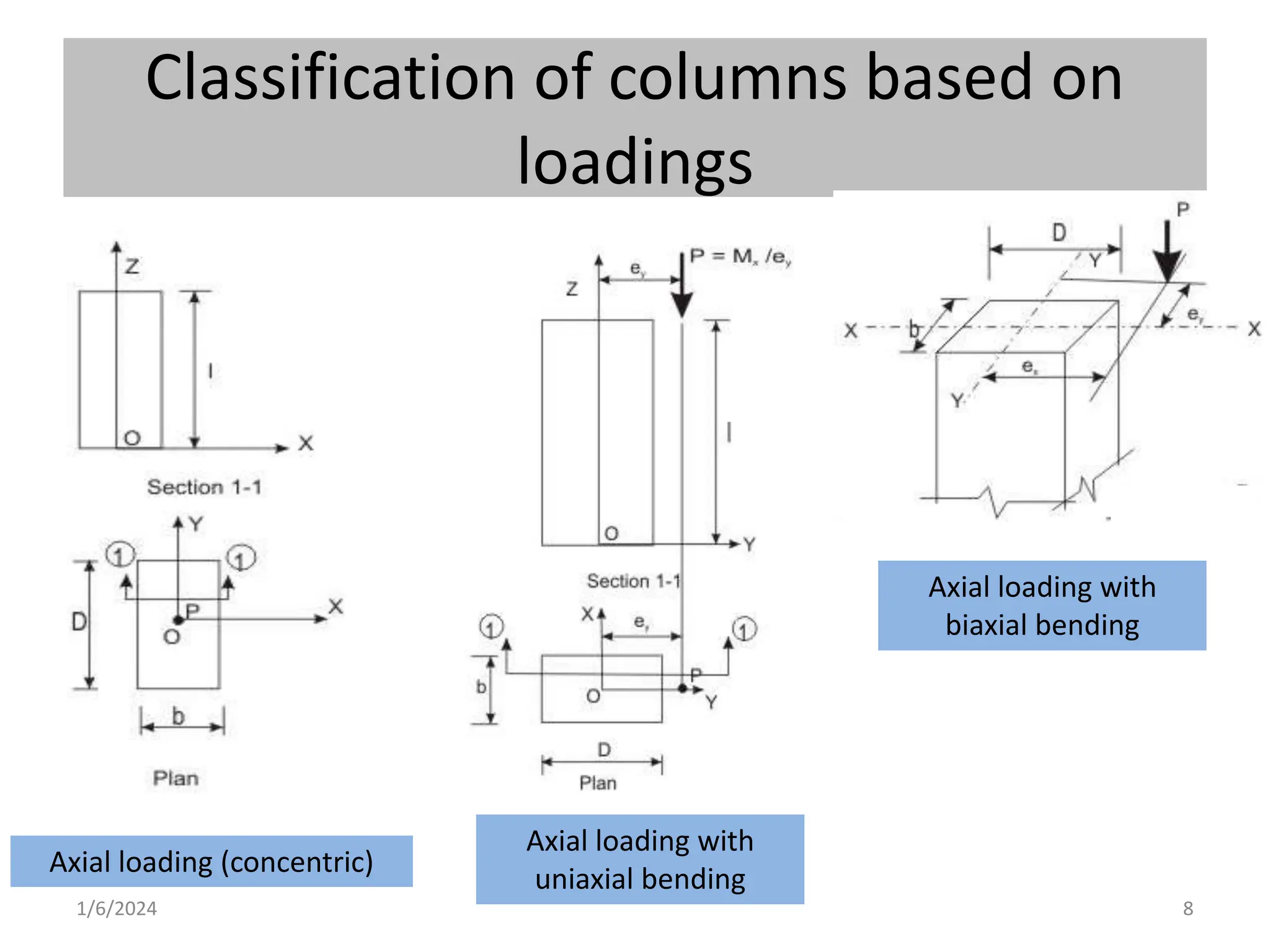
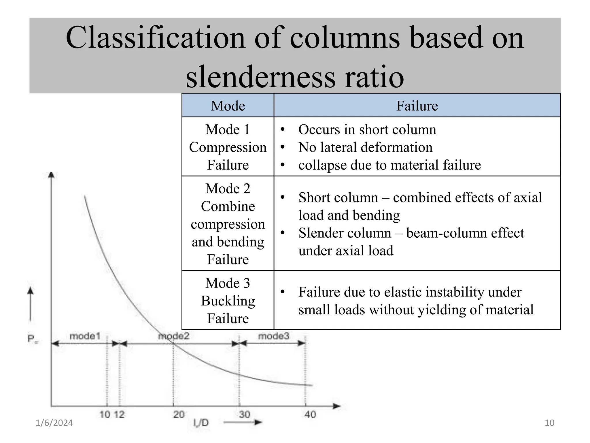
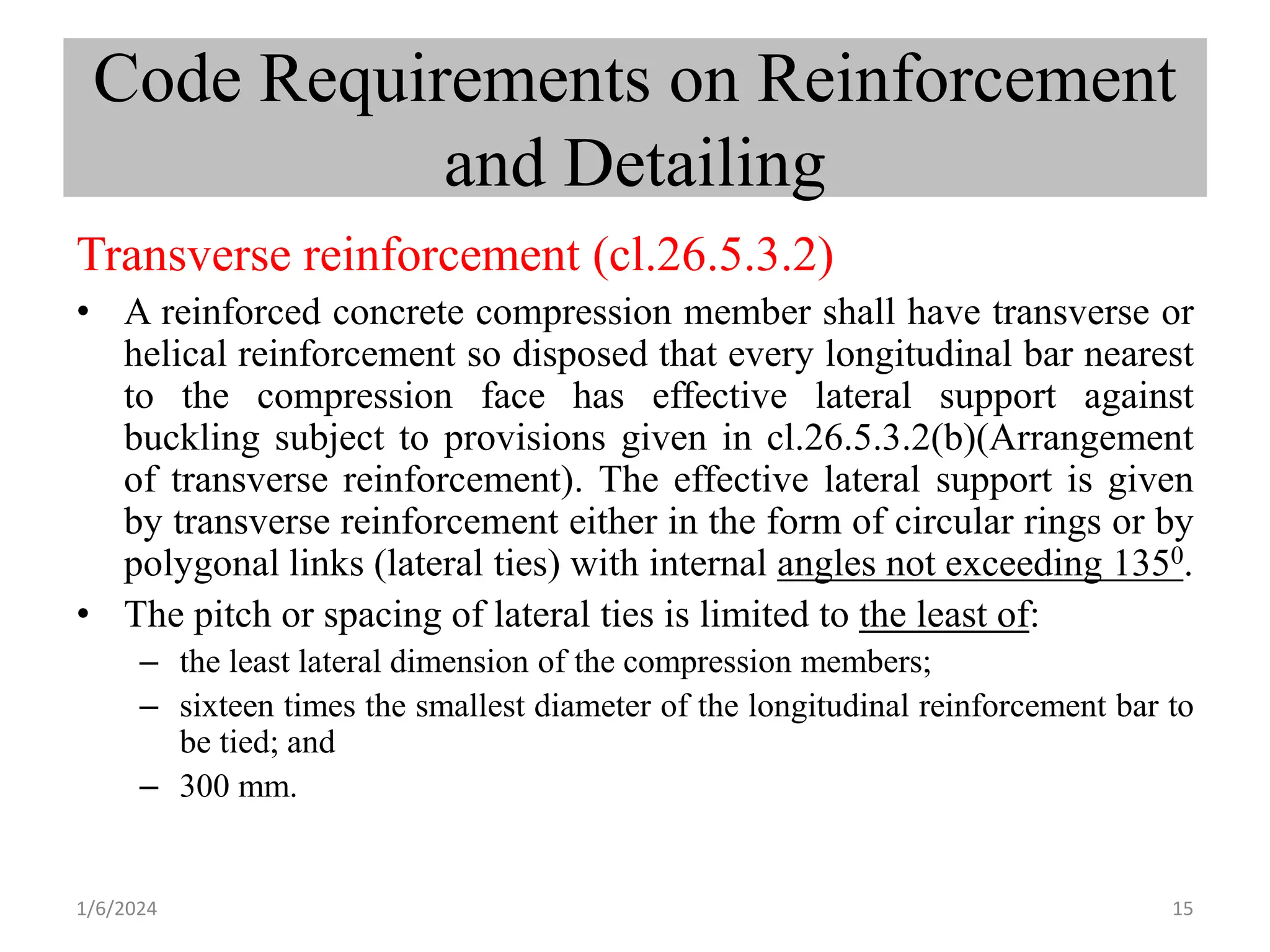
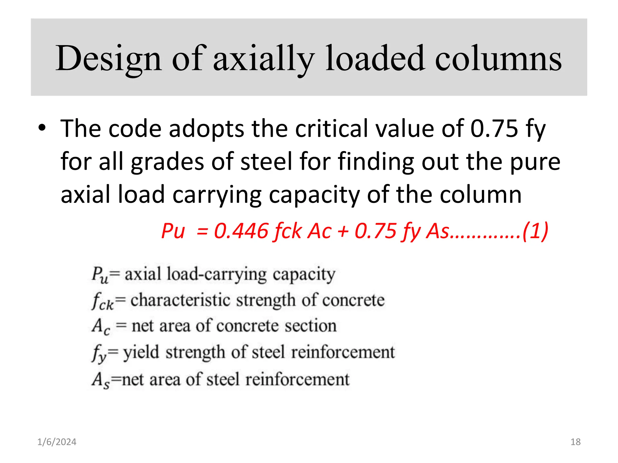
The document discusses various types of compression members including columns, pedestals, walls, and struts. It describes design considerations for compression members including strength and buckling resistance. It defines effective length as the vertical distance between points of inflection when the member buckles. Various classifications of columns are discussed based on loadings, slenderness ratio, and reinforcement type. Code requirements for longitudinal and transverse reinforcement as well as detailing are provided. Two examples of column design are included, one with axial load only and one with spiral reinforcement.
The document discusses the reinforcement requirements and design process for axially loaded columns. It provides guidelines on the minimum longitudinal and transverse reinforcement, including the pitch and diameter of lateral ties. Examples are given to calculate the ultimate load capacity of rectangular and circular columns based on the grade of concrete and steel. Design assumptions and checks for minimum eccentricity are also outlined.
Design of short columns using helical reinforcementshivam gautam
Helical reinforcement, also known as spiral reinforcement, is used in circular concrete columns. It consists of longitudinal bars enclosed within a continuously wound spiral reinforcement. Helical reinforcement is sometimes designed instead of normal links for columns because it provides increased strength and ductility. The spiral reinforcement acts compositely with the concrete core and allows the column to sustain higher loads than those with normal links. It also minimizes the risk of stirrups opening during seismic events. The document then provides details on the design of helical reinforcement for short concrete columns, including governing equations and an example problem.
This document discusses reinforced concrete columns. Columns act as vertical supports that transmit loads to foundations. Columns may fail due to compression failure, buckling, or a combination. Short columns are more prone to compression failure, while slender columns are more likely to buckle. Column sections can be square, circular, or rectangular. The dimensions and bracing affect whether a column is classified as short or slender. Longitudinal reinforcement and links are designed to resist axial loads and moments based on the column's effective height and end conditions. Design charts are used to determine reinforcement for columns with axial and uniaxial bending loads. Examples show how to design column reinforcement.
The document discusses reinforced concrete columns, including their functions, failure modes, classifications, and design considerations. Columns primarily resist axial compression but may also experience bending moments. They can fail due to compression, buckling, or a combination. Design depends on whether the column is short or slender, braced or unbraced. Reinforcement is determined based on the loads applied, including axial load only, symmetrical beam loading, or loading in one or two bending directions. Links are included to prevent bar buckling. Examples show how to design column longitudinal reinforcement and links for different load cases.
The document discusses reinforced concrete columns, including their functions, failure modes, classifications, and design considerations. Columns primarily resist axial compression but may also experience bending moments. They can fail due to compression, buckling, or a combination. Design depends on whether the column is short or slender, braced or unbraced. Reinforcement is designed based on the column's expected loads and dimensions using methods specified in design codes like BS 8110.
This document provides information on the design of reinforced concrete columns, including:
- Columns transmit loads vertically to foundations and may resist both compression and bending. Common cross-sections are square, circular and rectangular.
- Columns are classified as braced or unbraced depending on lateral stability, and short or slender based on buckling resistance. Short column design considers axial load capacity while slender column design accounts for second-order effects.
- Reinforcement details include minimum longitudinal bar size and spacing and design of lateral ties. Slender column design determines loadings and calculates moments from stiffness, deflection and biaxial bending effects. Design charts are used to select reinforcement for columns under axial and uniaxial
The document discusses different types of columns based on bracing, length, and reinforcement. It describes braced and unbraced columns, long and short columns, and tied, spiral, and composite columns. Requirements for minimum reinforcement, lateral ties, and selection of column size are also summarized.
This document provides an overview of member behavior for beams and columns in seismic design. It discusses the types of moment resisting frames and the principles for designing special moment resisting frames, including strong-column/weak-beam design, avoiding shear failure, and providing ductile details. Beam and column design considerations are covered, such as dimensions, reinforcement, and shear capacity. Beam-column joint design is also summarized, including dimensions, shear determination, and strength.
This document contains lecture notes on the design of concrete columns. It defines key terms like effective length, pedestal, column, and discusses the classification of columns based on type of reinforcement, loadings, and slenderness ratio. It describes the functions of bracing in columns and design requirements for longitudinal and transverse reinforcement. The document states assumptions in limit state design of columns and the need to consider minimum eccentricity in design. It concludes with sample exercises related to column design.
Calulation of deflection and crack width according to is 456 2000Vikas Mehta
This document discusses the calculation of crack width in reinforced concrete flexural members. It provides information on:
1) Crack width is calculated to satisfy serviceability limits and is only relevant for Type 3 pre-stressed concrete members that crack under service loads.
2) Crack width depends on factors like amount of pre-stress, tensile stress in bars, concrete cover thickness, bar diameter and spacing, member depth and location of neutral axis, bond strength, and concrete tensile strength.
3) The method of calculation involves determining the shortest distance from the surface to a bar and using equations involving member depth, neutral axis depth, average strain at the surface level. Permissible crack widths are specified depending on exposure
The document discusses buckling of columns under axial compression. It describes:
1) Different buckling theories including elastic buckling, inelastic buckling using tangent modulus theory and reduced modulus theory. Shanley's theory accounts for the effect of transverse displacement.
2) Factors affecting buckling strength including end conditions, initial crookedness, and residual stresses. Effective length accounts for end restraint.
3) Local buckling of thin plate elements can reduce the column's strength before its calculated buckling strength is reached. Flange and web buckling must be prevented.
This presentation summarizes information about reinforced concrete columns. It was presented by a group of 9 students from the Department of Civil Engineering at Dhaka University of Engineering & Technology to faculty members. The presentation defines columns, classifies columns based on shape, reinforcement, and loading, and describes the effective length, buckling modes, sizing, reinforcement, cover, lapping, hoop reinforcement, and failure modes of columns. The objectives are to understand column arrangement, design specifications, and characteristics.
A column is a vertical structural member subjected to compression and bending forces. Short columns fail through crushing or splitting, while slender columns fail through buckling. The document provides examples of calculating required reinforcement area and diameter for a short reinforced concrete column. It also provides examples of calculating the critical buckling load of a rod and determining a suitable universal column section for a given load based on its effective length and slenderness ratio.
This document discusses different types and classifications of columns. It defines a column as a vertical structural member primarily designed to carry axial compression loads. Columns can be classified based on their shape, reinforcement, and type of loading. Common shapes include square, rectangular, circular, L-shaped, and T-shaped sections. Reinforcement types include tied columns with tie bars, spiral columns with helical reinforcement, and composite columns with encased steel. Columns are either concentrically loaded with forces through the centroid, or eccentrically loaded off-center. The document also covers column capacity calculations, resistance factors, and provides an example problem.
This document discusses different types and classifications of columns. It defines a column as a vertical structural member primarily designed to carry axial compression loads. Columns can be classified based on their shape, reinforcement, and type of loading. Common shapes include square, rectangular, circular, L-shaped, and T-shaped sections. Reinforcement types include tied columns with ties, spiral columns with helical reinforcement, and composite columns with encased steel. Columns are either concentrically loaded with forces through the centroid, or eccentrically loaded off-center. The document also covers column capacity calculations, resistance factors, and provides an example problem.
This document discusses ductile detailing of reinforced concrete (RC) frames according to Indian standards. It explains that detailing involves translating the structural design into the final structure through reinforcement drawings. Good detailing ensures reinforcement and concrete interact efficiently. Key aspects of ductile detailing covered include requirements for beams, columns, and beam-column joints to improve ductility and seismic performance. Specific provisions are presented for longitudinal and shear reinforcement in beams and columns, as well as confining reinforcement and lap splices. The importance of cover and stirrup spacing is also discussed.
This document defines key terms related to compression members, classifies columns based on reinforcement type, loadings, and slenderness ratio, and outlines design assumptions. It defines effective length, pedestal, column, and wall. It classifies columns as tied, helically reinforced, or composite. Columns are classified by loadings as subjected to axial load only, axial with uniaxial bending, or axial with bi-axial bending. Columns are classified as short or slender based on slenderness ratios. Design assumes minimum eccentricity and considers different failure modes.
The document discusses the design of columns and footings in concrete structures. It covers various topics related to column design including classification of columns based on type of reinforcement, loading, and slenderness ratios. Short columns subjected to axial loads with or without eccentricity are analyzed. Design aspects such as effective length, minimum reinforcement requirements, cover and transverse tie spacing are described based on code specifications. Equations for equilibrium of uniformly loaded short columns are also presented.
chapter 4 flexural design of beam 2021.pdfAshrafZaman33
This chapter discusses the flexural analysis and design of beams. It covers fundamental assumptions for bending and shear stresses in beams. It also discusses bending behavior of homogeneous and reinforced concrete beams. The chapter includes analysis of cracked and uncracked beam sections, and design for flexure including underreinforced, overreinforced and balanced conditions. It also covers design of doubly reinforced beams, T-beams and practical considerations like concrete cover and bar spacing.
Because of torsion, the beam fails in diagonal tension forming the spiral cracks around the beam. Warping of the section does not allow a plane section to remain as plane after twisting. Clause 41 of IS 456:2000 provides the provisions for
the design of torsional reinforcements. The design rules for torsion are based on the equivalent moment.
The document discusses guidelines for detailing reinforcement in concrete structures. It begins by defining detailing as the preparation of working drawings showing the size and location of reinforcement. Good detailing ensures reinforcement and concrete interact efficiently. The document then discusses sources of tension in concrete structures from various loading conditions like bending, shear, and connections. It provides equations from AS3600-2009 for calculating minimum development lengths for reinforcing bars to develop their yield strength based on bar size, concrete strength, and transverse reinforcement. It also discusses lap splice requirements. In summary, the document provides best practice guidelines for detailing reinforcement to efficiently resist loads and control cracking in concrete structures.
This document discusses various types of beam and column connections used in steel structures. It describes rigid, pinned, and semi-rigid connections. It also discusses different beam to beam connections like web cleat angle, clip and seat angle, and web and seat angle connections. Beam to column connections including web angle, clip and seat angle stiffened and unstiffened are explained. Finally, it covers moment resistant connections like eccentrically loaded, light moment and heavy moment connections and provides examples of designing some typical connections.
This document provides an overview of the design of compression members (columns) in reinforced concrete structures. It discusses various types of columns based on reinforcement, loading conditions, and slenderness ratio. It describes the classification of columns as short or slender. The document also covers effective length, braced vs unbraced columns, codal provisions for reinforcement, and functions of longitudinal and transverse reinforcement. Key points include types of column reinforcement, minimum reinforcement requirements, cover requirements, and assumptions for the limit state of collapse under compression.
DSR chap4 shear and bond pdf.pptxxxxxxxxxxxxxxxxxxxxxxADITYAPILLAI29
Shear reinforcement is required in concrete beams when the shear stresses exceed the shear strength of the concrete. Shear reinforcement takes the form of vertical stirrups or bent-up bars from the longitudinal reinforcement. The design of shear reinforcement involves calculating the shear force, nominal shear stress, shear strength of the concrete, and determining the amount and spacing of shear reinforcement needed. Proper development length of the longitudinal bars is also important to ensure adequate bond between the steel and concrete.
KuberTENes Birthday Bash Guadalajara - K8sGPT first impressionsVictor Morales
K8sGPT is a tool that analyzes and diagnoses Kubernetes clusters. This presentation was used to share the requirements and dependencies to deploy K8sGPT in a local environment.
More Related Content
Similar to RCC column_Shortly Axially Loaded column.pptx
This document provides an overview of member behavior for beams and columns in seismic design. It discusses the types of moment resisting frames and the principles for designing special moment resisting frames, including strong-column/weak-beam design, avoiding shear failure, and providing ductile details. Beam and column design considerations are covered, such as dimensions, reinforcement, and shear capacity. Beam-column joint design is also summarized, including dimensions, shear determination, and strength.
This document contains lecture notes on the design of concrete columns. It defines key terms like effective length, pedestal, column, and discusses the classification of columns based on type of reinforcement, loadings, and slenderness ratio. It describes the functions of bracing in columns and design requirements for longitudinal and transverse reinforcement. The document states assumptions in limit state design of columns and the need to consider minimum eccentricity in design. It concludes with sample exercises related to column design.
Calulation of deflection and crack width according to is 456 2000Vikas Mehta
This document discusses the calculation of crack width in reinforced concrete flexural members. It provides information on:
1) Crack width is calculated to satisfy serviceability limits and is only relevant for Type 3 pre-stressed concrete members that crack under service loads.
2) Crack width depends on factors like amount of pre-stress, tensile stress in bars, concrete cover thickness, bar diameter and spacing, member depth and location of neutral axis, bond strength, and concrete tensile strength.
3) The method of calculation involves determining the shortest distance from the surface to a bar and using equations involving member depth, neutral axis depth, average strain at the surface level. Permissible crack widths are specified depending on exposure
The document discusses buckling of columns under axial compression. It describes:
1) Different buckling theories including elastic buckling, inelastic buckling using tangent modulus theory and reduced modulus theory. Shanley's theory accounts for the effect of transverse displacement.
2) Factors affecting buckling strength including end conditions, initial crookedness, and residual stresses. Effective length accounts for end restraint.
3) Local buckling of thin plate elements can reduce the column's strength before its calculated buckling strength is reached. Flange and web buckling must be prevented.
This presentation summarizes information about reinforced concrete columns. It was presented by a group of 9 students from the Department of Civil Engineering at Dhaka University of Engineering & Technology to faculty members. The presentation defines columns, classifies columns based on shape, reinforcement, and loading, and describes the effective length, buckling modes, sizing, reinforcement, cover, lapping, hoop reinforcement, and failure modes of columns. The objectives are to understand column arrangement, design specifications, and characteristics.
A column is a vertical structural member subjected to compression and bending forces. Short columns fail through crushing or splitting, while slender columns fail through buckling. The document provides examples of calculating required reinforcement area and diameter for a short reinforced concrete column. It also provides examples of calculating the critical buckling load of a rod and determining a suitable universal column section for a given load based on its effective length and slenderness ratio.
This document discusses different types and classifications of columns. It defines a column as a vertical structural member primarily designed to carry axial compression loads. Columns can be classified based on their shape, reinforcement, and type of loading. Common shapes include square, rectangular, circular, L-shaped, and T-shaped sections. Reinforcement types include tied columns with tie bars, spiral columns with helical reinforcement, and composite columns with encased steel. Columns are either concentrically loaded with forces through the centroid, or eccentrically loaded off-center. The document also covers column capacity calculations, resistance factors, and provides an example problem.
This document discusses different types and classifications of columns. It defines a column as a vertical structural member primarily designed to carry axial compression loads. Columns can be classified based on their shape, reinforcement, and type of loading. Common shapes include square, rectangular, circular, L-shaped, and T-shaped sections. Reinforcement types include tied columns with ties, spiral columns with helical reinforcement, and composite columns with encased steel. Columns are either concentrically loaded with forces through the centroid, or eccentrically loaded off-center. The document also covers column capacity calculations, resistance factors, and provides an example problem.
This document discusses ductile detailing of reinforced concrete (RC) frames according to Indian standards. It explains that detailing involves translating the structural design into the final structure through reinforcement drawings. Good detailing ensures reinforcement and concrete interact efficiently. Key aspects of ductile detailing covered include requirements for beams, columns, and beam-column joints to improve ductility and seismic performance. Specific provisions are presented for longitudinal and shear reinforcement in beams and columns, as well as confining reinforcement and lap splices. The importance of cover and stirrup spacing is also discussed.
This document defines key terms related to compression members, classifies columns based on reinforcement type, loadings, and slenderness ratio, and outlines design assumptions. It defines effective length, pedestal, column, and wall. It classifies columns as tied, helically reinforced, or composite. Columns are classified by loadings as subjected to axial load only, axial with uniaxial bending, or axial with bi-axial bending. Columns are classified as short or slender based on slenderness ratios. Design assumes minimum eccentricity and considers different failure modes.
The document discusses the design of columns and footings in concrete structures. It covers various topics related to column design including classification of columns based on type of reinforcement, loading, and slenderness ratios. Short columns subjected to axial loads with or without eccentricity are analyzed. Design aspects such as effective length, minimum reinforcement requirements, cover and transverse tie spacing are described based on code specifications. Equations for equilibrium of uniformly loaded short columns are also presented.
chapter 4 flexural design of beam 2021.pdfAshrafZaman33
This chapter discusses the flexural analysis and design of beams. It covers fundamental assumptions for bending and shear stresses in beams. It also discusses bending behavior of homogeneous and reinforced concrete beams. The chapter includes analysis of cracked and uncracked beam sections, and design for flexure including underreinforced, overreinforced and balanced conditions. It also covers design of doubly reinforced beams, T-beams and practical considerations like concrete cover and bar spacing.
Because of torsion, the beam fails in diagonal tension forming the spiral cracks around the beam. Warping of the section does not allow a plane section to remain as plane after twisting. Clause 41 of IS 456:2000 provides the provisions for
the design of torsional reinforcements. The design rules for torsion are based on the equivalent moment.
The document discusses guidelines for detailing reinforcement in concrete structures. It begins by defining detailing as the preparation of working drawings showing the size and location of reinforcement. Good detailing ensures reinforcement and concrete interact efficiently. The document then discusses sources of tension in concrete structures from various loading conditions like bending, shear, and connections. It provides equations from AS3600-2009 for calculating minimum development lengths for reinforcing bars to develop their yield strength based on bar size, concrete strength, and transverse reinforcement. It also discusses lap splice requirements. In summary, the document provides best practice guidelines for detailing reinforcement to efficiently resist loads and control cracking in concrete structures.
This document discusses various types of beam and column connections used in steel structures. It describes rigid, pinned, and semi-rigid connections. It also discusses different beam to beam connections like web cleat angle, clip and seat angle, and web and seat angle connections. Beam to column connections including web angle, clip and seat angle stiffened and unstiffened are explained. Finally, it covers moment resistant connections like eccentrically loaded, light moment and heavy moment connections and provides examples of designing some typical connections.
This document provides an overview of the design of compression members (columns) in reinforced concrete structures. It discusses various types of columns based on reinforcement, loading conditions, and slenderness ratio. It describes the classification of columns as short or slender. The document also covers effective length, braced vs unbraced columns, codal provisions for reinforcement, and functions of longitudinal and transverse reinforcement. Key points include types of column reinforcement, minimum reinforcement requirements, cover requirements, and assumptions for the limit state of collapse under compression.
DSR chap4 shear and bond pdf.pptxxxxxxxxxxxxxxxxxxxxxxADITYAPILLAI29
Shear reinforcement is required in concrete beams when the shear stresses exceed the shear strength of the concrete. Shear reinforcement takes the form of vertical stirrups or bent-up bars from the longitudinal reinforcement. The design of shear reinforcement involves calculating the shear force, nominal shear stress, shear strength of the concrete, and determining the amount and spacing of shear reinforcement needed. Proper development length of the longitudinal bars is also important to ensure adequate bond between the steel and concrete.
Similar to RCC column_Shortly Axially Loaded column.pptx (20)
KuberTENes Birthday Bash Guadalajara - K8sGPT first impressionsVictor Morales
K8sGPT is a tool that analyzes and diagnoses Kubernetes clusters. This presentation was used to share the requirements and dependencies to deploy K8sGPT in a local environment.
A SYSTEMATIC RISK ASSESSMENT APPROACH FOR SECURING THE SMART IRRIGATION SYSTEMSIJNSA Journal
The smart irrigation system represents an innovative approach to optimize water usage in agricultural and landscaping practices. The integration of cutting-edge technologies, including sensors, actuators, and data analysis, empowers this system to provide accurate monitoring and control of irrigation processes by leveraging real-time environmental conditions. The main objective of a smart irrigation system is to optimize water efficiency, minimize expenses, and foster the adoption of sustainable water management methods. This paper conducts a systematic risk assessment by exploring the key components/assets and their functionalities in the smart irrigation system. The crucial role of sensors in gathering data on soil moisture, weather patterns, and plant well-being is emphasized in this system. These sensors enable intelligent decision-making in irrigation scheduling and water distribution, leading to enhanced water efficiency and sustainable water management practices. Actuators enable automated control of irrigation devices, ensuring precise and targeted water delivery to plants. Additionally, the paper addresses the potential threat and vulnerabilities associated with smart irrigation systems. It discusses limitations of the system, such as power constraints and computational capabilities, and calculates the potential security risks. The paper suggests possible risk treatment methods for effective secure system operation. In conclusion, the paper emphasizes the significant benefits of implementing smart irrigation systems, including improved water conservation, increased crop yield, and reduced environmental impact. Additionally, based on the security analysis conducted, the paper recommends the implementation of countermeasures and security approaches to address vulnerabilities and ensure the integrity and reliability of the system. By incorporating these measures, smart irrigation technology can revolutionize water management practices in agriculture, promoting sustainability, resource efficiency, and safeguarding against potential security threats.
Advanced control scheme of doubly fed induction generator for wind turbine us...IJECEIAES
This paper describes a speed control device for generating electrical energy on an electricity network based on the doubly fed induction generator (DFIG) used for wind power conversion systems. At first, a double-fed induction generator model was constructed. A control law is formulated to govern the flow of energy between the stator of a DFIG and the energy network using three types of controllers: proportional integral (PI), sliding mode controller (SMC) and second order sliding mode controller (SOSMC). Their different results in terms of power reference tracking, reaction to unexpected speed fluctuations, sensitivity to perturbations, and resilience against machine parameter alterations are compared. MATLAB/Simulink was used to conduct the simulations for the preceding study. Multiple simulations have shown very satisfying results, and the investigations demonstrate the efficacy and power-enhancing capabilities of the suggested control system.
Understanding Inductive Bias in Machine LearningSUTEJAS
This presentation explores the concept of inductive bias in machine learning. It explains how algorithms come with built-in assumptions and preferences that guide the learning process. You'll learn about the different types of inductive bias and how they can impact the performance and generalizability of machine learning models.
The presentation also covers the positive and negative aspects of inductive bias, along with strategies for mitigating potential drawbacks. We'll explore examples of how bias manifests in algorithms like neural networks and decision trees.
By understanding inductive bias, you can gain valuable insights into how machine learning models work and make informed decisions when building and deploying them.
Harnessing WebAssembly for Real-time Stateless Streaming PipelinesChristina Lin
Traditionally, dealing with real-time data pipelines has involved significant overhead, even for straightforward tasks like data transformation or masking. However, in this talk, we’ll venture into the dynamic realm of WebAssembly (WASM) and discover how it can revolutionize the creation of stateless streaming pipelines within a Kafka (Redpanda) broker. These pipelines are adept at managing low-latency, high-data-volume scenarios.
Introduction- e - waste – definition - sources of e-waste– hazardous substances in e-waste - effects of e-waste on environment and human health- need for e-waste management– e-waste handling rules - waste minimization techniques for managing e-waste – recycling of e-waste - disposal treatment methods of e- waste – mechanism of extraction of precious metal from leaching solution-global Scenario of E-waste – E-waste in India- case studies.
International Conference on NLP, Artificial Intelligence, Machine Learning an...gerogepatton
International Conference on NLP, Artificial Intelligence, Machine Learning and Applications (NLAIM 2024) offers a premier global platform for exchanging insights and findings in the theory, methodology, and applications of NLP, Artificial Intelligence, Machine Learning, and their applications. The conference seeks substantial contributions across all key domains of NLP, Artificial Intelligence, Machine Learning, and their practical applications, aiming to foster both theoretical advancements and real-world implementations. With a focus on facilitating collaboration between researchers and practitioners from academia and industry, the conference serves as a nexus for sharing the latest developments in the field.
A review on techniques and modelling methodologies used for checking electrom...nooriasukmaningtyas
The proper function of the integrated circuit (IC) in an inhibiting electromagnetic environment has always been a serious concern throughout the decades of revolution in the world of electronics, from disjunct devices to today’s integrated circuit technology, where billions of transistors are combined on a single chip. The automotive industry and smart vehicles in particular, are confronting design issues such as being prone to electromagnetic interference (EMI). Electronic control devices calculate incorrect outputs because of EMI and sensors give misleading values which can prove fatal in case of automotives. In this paper, the authors have non exhaustively tried to review research work concerned with the investigation of EMI in ICs and prediction of this EMI using various modelling methodologies and measurement setups.
Literature Review Basics and Understanding Reference Management.pptxDr Ramhari Poudyal
Three-day training on academic research focuses on analytical tools at United Technical College, supported by the University Grant Commission, Nepal. 24-26 May 2024
1. Compression Members
• Vertical Structural members
• Transmits axial compressive loads with or
without moment
• Design considerations
– Strength
– Buckling
• Examples : Pedestal, column, wall and strut
1/6/2024 1
2. • Effective length
– The vertical distance between the points of
inflection of the compression member in the
buckled configuration in a plane is termed as
effective length le of that compression member in
that plane. If l is the unsupported length, then
– Clause 25.2 of IS 456:2000 stipulates the effective
lengths of compression members
le = kl
1/6/2024 2
5. Major and Minor axis of Column
Major Axis : Axis about which the moment of Inertia of column is
more than the moment of inertia about other perpendicular axis
Minor Axis : Axis about which the moment of Inertia of column is less
than the moment of inertia about other perpendicular axis
1/6/2024 5
6. Compression Members
• Pedestal (IS 456:2000 cl. 26.5.3)
– l <= 3 times least horizontal dimension, say b
– other horizontal dimension <= 4 times b
• Column (IS 456:2000 cl. 25.3)
– unsupported length, l <= 60 times least
dimension, if restrained at both ends
• Wall (IS 456:2000 cl. 32.2.3)
– Effective height to thickness ratio <= 30
1/6/2024 6
7. Classification of columns based on
types of reinforcement
Column with transverse
(lateral ties) reinforcement Column with helical
reinforcement
Composite columns
with steel sections
1/6/2024 7
8. Classification of columns based on
loadings
Axial loading (concentric)
Axial loading with
uniaxial bending
Axial loading with
biaxial bending
1/6/2024 8
9. Column with axial loading (concentric)
Column with axial loads and uniaxial bending
Column with axial loads and biaxial bending
1/6/2024 9
10. Classification of columns based on
slenderness ratio
Mode Failure
Mode 1
Compression
Failure
• Occurs in short column
• No lateral deformation
• collapse due to material failure
Mode 2
Combine
compression
and bending
Failure
• Short column – combined effects of axial
load and bending
• Slender column – beam-column effect
under axial load
Mode 3
Buckling
Failure
• Failure due to elastic instability under
small loads without yielding of material
1/6/2024 10
11. Classification of columns based on
slenderness ratio
According to code (Cl.25.1.2)
•Short Column – (Lex/D) & (Ley/b) < 12
•Long Column – (Lex/D) OR (Ley/b) ≥ 12
Lex = Effective length in respect of the major axis
D = Depth w.r.t. major axis
Ley = Effective length in respect of the minor axis
b = Width of the member
1/6/2024 11
12. • cl. 25.3.1 the maximum unsupported length between
two restraints of a column to sixty times its least
lateral dimension.
l/d ≤ 60
• For cantilever columns, when one end of the column
is unrestrained, the unsupported length is restricted
to 100b2/D where b and D are as defined earlier
cl.25 Compression members
1/6/2024 12
13. Code Requirements on Reinforcement
and Detailing
Longitudinal reinforcement (cl.26.5.3.1)
• The minimum amount of steel should be at least 0.8% of the
gross cross-sectional area of the column required.
• The maximum amount of steel should be 4% of the gross
cross-sectional area of the column so that it does not exceed
6 per cent when bars from column below have to be lapped
with those in the column under consideration.
• Four and six are the minimum number of longitudinal bars in
rectangular and circular columns, respectively.
• The diameter of the longitudinal bars should be at least 12
mm.
1/6/2024 13
14. Code Requirements on Reinforcement
and Detailing
• Columns having helical reinforcement shall have at
least six longitudinal bars within and in contact with
the helical reinforcement. The bars shall be placed
equidistant around its inner circumference.
• The bars shall be spaced not exceeding 300 mm
along the periphery of the column.
• The amount of reinforcement for pedestal shall be at
least 0.15 per cent of the cross-sectional area
provided
1/6/2024 14
15. Code Requirements on Reinforcement
and Detailing
Transverse reinforcement (cl.26.5.3.2)
• A reinforced concrete compression member shall have transverse or
helical reinforcement so disposed that every longitudinal bar nearest
to the compression face has effective lateral support against
buckling subject to provisions given in cl.26.5.3.2(b)(Arrangement
of transverse reinforcement). The effective lateral support is given
by transverse reinforcement either in the form of circular rings or by
polygonal links (lateral ties) with internal angles not exceeding 1350.
• The pitch or spacing of lateral ties is limited to the least of:
– the least lateral dimension of the compression members;
– sixteen times the smallest diameter of the longitudinal reinforcement bar to
be tied; and
– 300 mm.
1/6/2024 15
16. Design of axially loaded columns
rm = 1.5 for Concrete
Stress = 0.67fck/1.5 = 0.446 fck
rm = 1.15 for Steel
Stress = fy/1.5 = 0.87fy
1/6/2024 16
17. • The stress corresponding to 0.002 strain in steel bars are as follows:
Grade of Steel Stress
Corresponding to
0.002 Strain
Fe250 0.87 fy
Fe 415 0.79 fy
Fe 500 0.75 fy
1/6/2024 17
18. Design of axially loaded columns
• The code adopts the critical value of 0.75 fy
for all grades of steel for finding out the pure
axial load carrying capacity of the column
Pu = 0.446 fck Ac + 0.75 fy As………….(1)
1/6/2024 18
19. Design of axially loaded columns
• Due to Rigid frame action, lateral loadings and
practical aspects of construction axially loaded
columns are subjected to bending moments.
• Minimum eccentricity as specified in code
(Clause 25.4) need to be considered
• emin Should be Greater of
– (unsupported length/500 + lateral dimension/30)
– 20 mm
1/6/2024 19
20. Design of axially loaded columns
• When emin does not exceed 0.05 times the lateral
dimension, code permits the use of following
simplified formula obtained by reducing Pu (Given in
equation 1 ) by approx. 10% (cl. 39.3)
Pu = 0.4 fck Ac + 0.67 fy As
1/6/2024 20
21. 𝑃𝑢 = 0.40𝑓𝑐𝑘𝐴𝑐 + 0.67𝑓𝑦𝐴𝑠
𝑃𝑢 = 0.40𝑓𝑐𝑘(𝐴𝑔−𝐴𝑠) + 0.67𝑓𝑦𝐴𝑠
𝑃𝑢 = 0.40𝑓𝑐𝑘𝐴𝑔(1 − 𝑝) + 0.67𝑓𝑦𝑝𝐴𝑔
• 𝐴𝑔= gross area of the section
• 𝑝= percentage of steel reinforcement
Design of axially loaded columns
1/6/2024 21
22. Compression Member with Helical
Reinforcement
• The strength of compression
members with helical reinforcement
shall be taken as 1.05 times the
strength of similar member with
lateral ties.
Pu = 1.05*(0.4 fck Ac + 0.67 fy As)
•The ratio of the volume of helical
reinforcement to the volume of the
core shall not be less than
0.36(Ag/Ac-1)*fck/fy
1/6/2024 22
23. • 𝑣𝑜𝑙𝑢𝑚𝑒 𝑜𝑓 ℎ𝑒𝑙𝑖𝑐𝑎𝑙 𝑟𝑒𝑖𝑛𝑓𝑜𝑟𝑐𝑒𝑚𝑒𝑛𝑡
𝑣𝑜𝑙𝑢𝑚𝑒 𝑜𝑓 𝑐𝑜𝑟𝑒(𝑉𝑐)
≥ 0.36
𝐴𝑔
𝐴𝑐
− 1 ∗
𝑓𝑐𝑘
𝑓𝑦
• 𝑣𝑜𝑙𝑢𝑚𝑒 𝑜𝑓 ℎ𝑒𝑙𝑖𝑐𝑎𝑙 𝑟𝑒𝑖𝑛𝑓𝑜𝑟𝑐𝑒𝑚𝑒𝑛𝑡 =
𝜋(𝐷𝑐−𝜑𝑠𝑝
)∗asp
• 𝑉𝑜𝑙𝑢𝑚𝑒 𝑜𝑓 𝑐𝑜𝑟𝑒 = 𝜋
4
∗ Dc2 ∗ 𝑆𝑣
•
𝜋(𝐷𝑐−𝜑𝑠𝑝
)∗asp
𝜋
4
∗Dc2∗Sv
≥ 0.36
𝐴𝑔
𝐴𝑐
− 1 ∗
𝑓𝑐𝑘
𝑓𝑦
Dc = Dia. of core
𝜑𝑠𝑝 = Dia. of spiral reinforcement
asp = Area of cross section of spiral reinforcement
Sv = pitch of spiral reinforcement
1/6/2024 23
25. Q. Design the reinforcement in a column of size 400 mm x 600 mm
subjected to an axial load of 2000 KN under service dead load and
live load. The column has an unsupported length of 4.0 m and
effectively held in position and restrained against rotation in both
ends. Use M 25 concrete and Fe 415 steel.
Slenderness Check
𝑙𝑒𝑥/𝐷𝑥 = 2600/600=4.33 < 12
𝑙𝑒𝑦/𝐷𝑦 = 2600/400=6.5 < 12
Hence it is a short column
Minimum Eccentricity
ex min = Greater of (lx/500+D/30) and 20 mm
= Greater of (4000/500 + 600/30) and 20 mm
= 28 mm and 20 mm => 28 mm
As per IS-456: Table 28,
Theoretical value = 0.5L
Recommended value =0.65L
=0.65*4000=2600
1/6/2024 25
26. ey min = Greater of (ly/500+Dy/30) and 20 mm
= Greater of (4000/500 + 400/30) and 20 mm
= 21.33 mm and 20 mm => 21.33 mm
0.05*Dx = 0.05*600 =30 mm > ex min (28mm)
0.05*Dy = 0.05*400 = 20 mm ~ ey min (21.33 mm)
• When emin does not exceed 0.05 times the lateral
dimension, code permits the use of simplified
formula.
1/6/2024 26
27. 𝑃𝑢 = 0.40𝑓𝑐𝑘𝐴𝑐 + 0.67𝑓𝑦
𝑃𝑢 = 0.40𝑓𝑐𝑘(𝐴𝑔 − 𝐴𝑠) + 0.67𝑓𝑦𝐴𝑠
3000*103 = 0.4 *25*(400 *600- As) + 0.67*415*As
As = 2238.39 mm2
Provide #6 Nos. 20 mm dia. Bars and #2 Nos. 16 mm dia. Bars
Hence Area provided = 2287 mm2
% Reinforcement Pt = (As/bd)*100
Pt = 0.953 > 0.8% & < 4% (cl. 26.5.3.2)……..OK.
Lateral Ties
Not less than…… i. φ/4 and
ii. 6 mm
Here φ is the largest bar diameter in the longitudinal reinforcement
Consider 8 mm dia. lateral ties which is currently being used in
field.
1/6/2024 27
28. Pitch ……. cl.26.5.3.2
i. the least lateral dimension of the column = 400 mm
ii. sixteen times the smallest diameter of longitudinal
reinforcement bar to be tied = 16(16) = 256 mm
iii. 300 mm
Use a pitch of 250 mm
1/6/2024 28
29. Design a reinforced concrete spiral column of 390
mm diameter subjected to an axial factored load of
1750 kN. The column is braced against side sway and
has unsupported length of 3.3 m. The concrete mix
and steel to be used in construction are of grades M25
and Fe415, respectively.
1/6/2024 29
31. Design of Spiral steel
Conside a bar dia. Of 8 mm and pitch Sv
Dia. Of the Core Dc = 390-40-40 = 310 mm
Dia. Of the helix Dsp = 390-40-40-8 = 302 mm
As per cl. 39.4.1
𝑣𝑜𝑙𝑢𝑚𝑒 𝑜𝑓 ℎ𝑒𝑙𝑖𝑐𝑎𝑙 𝑟𝑒𝑖𝑛𝑓𝑜𝑟𝑐𝑒𝑚𝑒𝑛𝑡
𝑣𝑜𝑙𝑢𝑚𝑒 𝑜𝑓 𝑐𝑜𝑟𝑒(𝑉𝑐)
≥ 0.36
𝐴𝑔
𝐴𝑐
− 1 ∗
𝑓𝑐𝑘
𝑓𝑦
𝜋(𝐷𝑐−𝜑𝑠𝑝
)∗asp
𝜋
4
∗Dc2∗Sv
≥ 0.36
𝐴𝑔
𝐴𝑐
− 1 ∗
𝑓𝑐𝑘
𝑓𝑦
Dc = Dia. of core
φsp = Dia. of spiral reinforcement
asp = Area of cross section of spiral reinforcement
Sv = pitch of spiral reinforcement
1/6/2024 31