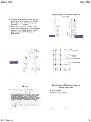
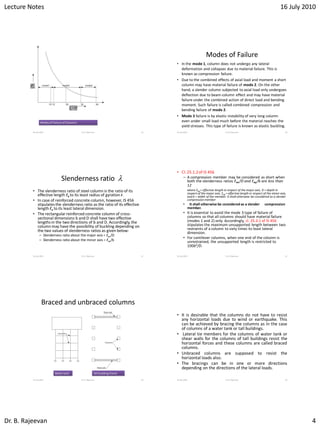
This document contains lecture notes on the design of concrete columns. It defines key terms like effective length, pedestal, column, and discusses the classification of columns based on type of reinforcement, loadings, and slenderness ratio. It describes the functions of bracing in columns and design requirements for longitudinal and transverse reinforcement. The document states assumptions in limit state design of columns and the need to consider minimum eccentricity in design. It concludes with sample exercises related to column design.
This document discusses the design of compression members subjected to axial load and biaxial bending. It introduces the concept of biaxial eccentricities and explains that columns should be designed considering possible eccentricities in two axes. The document outlines the method suggested by IS 456-2000, which is based on Breslar's load contour approach. It relates the parameter αn to the ratio of Pu/Puz. Finally, it provides a step-by-step process for designing the column section, which involves determining uniaxial moment capacities, computing permissible moment values from charts, and revising the section if needed. It also briefly mentions the simplified method according to BS8110.
This document provides an overview of the design of compression members (columns) in reinforced concrete structures. It discusses various types of columns based on reinforcement, loading conditions, and slenderness ratio. It describes the classification of columns as short or slender. The document also covers effective length, braced vs unbraced columns, codal provisions for reinforcement, and functions of longitudinal and transverse reinforcement. Key points include types of column reinforcement, minimum reinforcement requirements, cover requirements, and assumptions for the limit state of collapse under compression.
Structural engineering i- Dr. Iftekhar Anam
Structural Stability and Determinacy,Axial Force, Shear Force and Bending Moment Diagram of Frames,Axial Force, Shear Force and Bending Moment Diagram of Multi-Storied Frames,Influence Lines of Beams using Müller-Breslau’s Principle,Influence Lines of Plate Girders and Trusses,Maximum ‘Support Reaction’ due to Wheel Loads,Maximum ‘Shear Force’ due to Wheel Loads,Calculation of Wind Load,Seismic Vibration and Structural Response
http://www.uap-bd.edu/ce/anam/
One way slab is designed for an office building room measuring 3.2m x 9.2m. The slab is 150mm thick with 10mm diameter reinforcement bars spaced 230mm centre to centre. It is simply supported on 300mm thick walls and designed to support a 2.5kN/m2 live load. Reinforcement provided meets code requirements for minimum area and spacing. Design checks for cracking, deflection, development length and shear are within code limits.
Class notes of Geotechnical Engineering course I used to teach at UET Lahore. Feel free to download the slide show.
Anyone looking to modify these files and use them for their own teaching purposes can contact me directly to get hold of editable version.
The document discusses the direct stiffness method for analyzing truss structures. This method treats each individual truss element as a structure and develops the element stiffness matrix. Transformation matrices are used to relate element deformations to structure deformations. The total structure stiffness matrix is obtained by assembling the individual element stiffness matrices based on how the elements are connected at joints in the structure. This direct stiffness method forms the basis for computer programs to analyze truss structures.
This document discusses soil mechanics concepts related to lateral earth pressure. It defines active and passive earth pressures and describes Rankine's theory and assumptions for calculating lateral pressures on retaining walls. Equations are provided for determining active and passive earth pressure coefficients and distributions for cohesionless and cohesive soils. The effects of groundwater, surcharges, and sloping backfills are also examined. Sample problems are included to calculate lateral earth pressures and forces on retaining walls for different soil and loading conditions.
The document analyzes and designs reinforced concrete beams using the strength design method. It provides examples of designing a simply supported rectangular beam, a cantilever beam, and an overhanging beam. The solutions include calculating loads, moments, required reinforcement, checking deflection requirements, and verifying the strength of the designed sections.
The document provides steps for designing different structural elements:
1. Design of a beam subjected to torsion including calculation of torsional and bending moments, determination of steel requirements, and detailing.
2. Design of continuous beams involving calculation of bending moments and shears, reinforcement sizing, shear design, deflection check, and detailing including curtailment.
3. Design of circular water tanks with both flexible base and rigid base using approximate and IS code methods. This includes sizing hoop and vertical tension reinforcement, sizing wall thickness, designing cantilever sections and base slabs, and providing detailing diagrams.
Prestressed concrete uses tensioned steel to put concrete in compression and improve its performance. Circular structures like pipes, tanks and poles are well-suited for circular prestressing using hoop tension to counteract internal fluid pressure. Pipes can be made through monolithic, two-stage or precast construction. Design considerations include stresses from handling, support conditions, working pressure and cracking. Tanks come in different shapes and are analyzed as shells. Poles are designed for various loads as vertical cantilevers with tapering cross-sections.
The document provides information about prestressed concrete design. It discusses various topics related to prestress loss including immediate losses like elastic shortening, anchorage slip, and friction; and time-dependent losses like creep, shrinkage, and relaxation of steel. It describes the different types of prestressing systems and losses associated with pre-tensioning and post-tensioning. Methods to estimate total prestress losses including lump sum approximations and refined estimations are also presented.
information on types of beams, different methods to calculate beam stress, design for shear, analysis for SRB flexure, design for flexure, Design procedure for doubly reinforced beam,
The document discusses the moment distribution method for analyzing statically indeterminate structures. It begins by outlining the basic principles and definitions of the method, including stiffness factors, carry-over factors, and distribution factors. It then provides an example problem, showing the calculation of fixed end moments, establishment of the distribution table through successive approximations, and determination of shear forces and bending moments. Finally, it discusses extensions of the method to structures with non-prismatic members, including using tables to determine necessary values for analysis.
1. The document discusses stresses in solids due to eccentric and combined loading, including bending and direct stresses.
2. It defines the core of a section as the area where a load can be applied without causing tensile stress. For a rectangular section, the core is a rhombus with diagonals of B/3 and D/3.
3. Wind loading on structures like walls and chimneys is also analyzed, calculating bending moments and resultant stresses. Maintaining compressive stresses only is important for structural integrity.
The document discusses different types of columns based on bracing, length, and reinforcement. It describes braced and unbraced columns, long and short columns, and tied, spiral, and composite columns. Requirements for minimum reinforcement, lateral ties, and selection of column size are also summarized.
6161103 3.4 three dimensional force systemsetcenterrbru
1) Three-dimensional force systems involve resolving forces into x, y, and z components and using the equations of equilibrium to solve for unknown forces.
2) Examples are provided of using free body diagrams and the equations of equilibrium to solve for tensions in cables, magnitudes of applied forces, and stretches of springs in static systems with multiple forces.
3) Unknown forces and stretches are determined by setting the vector sum of the forces in x, y, and z directions equal to zero and solving the resulting simultaneous equations.
This document discusses the design of biaxially loaded columns. It defines a biaxially loaded column as one where axial load acts with eccentricities about both principal axes, causing bending in two directions. Several methods for analyzing and designing biaxially loaded columns are presented, including the load contour method, reciprocal load method, strain compatibility method, and equivalent eccentricity method. An example problem demonstrates using the reciprocal load method to check the adequacy of a trial reinforced concrete column design subjected to biaxial bending.
this slide will clear all the topics and problem related to singly reinforced beam by limit state method, things are explained with diagrams , easy to understand .
This document discusses reinforced concrete columns. It begins by defining columns and different column types, including based on shape, reinforcement, loading conditions, and slenderness ratio. Short columns fail due to material strength while slender columns are at risk of buckling. The document covers column design considerations like unsupported length and effective length. It provides examples of single storey building column design and discusses minimum longitudinal reinforcement requirements in columns.
The document discusses the design of slender columns. It defines a slender column as having a slenderness ratio (length to least lateral dimension) greater than 12. Slender columns experience appreciable lateral deflection even under axial loads alone. The design of slender columns can be done using three methods - the strength reduction coefficient method, additional moment method, or moment magnification method. The document outlines the step-by-step procedure for designing a slender column using the additional moment method, which involves determining the effective length, initial moments, additional moments, total moments accounting for a reduction coefficient, and redesigning the column for combined axial load and bending.
This document provides an overview of mechanics of solids (or strength of materials) including definitions of key terms like stress, strain, elasticity and their relationships. It discusses stress analysis for axially loaded members and introduces various stress conditions in 2D and 3D spaces. Stress is defined as internal resistance against deformation while strain is a measure of deformation. Different material types like isotropic, orthotropic and their elastic relationships are also covered.
This document discusses mechanics of solids and the effects of moving loads on beams and girders. It addresses maximum moments that occur for single moving loads, two moving loads, and three moving loads. For a single load, the maximum moment is when the load is at midspan. For two loads, the maximum moment formula is provided. For three loads, the maximum moment under each load is calculated by finding the resultant load and distance to the load. Numerical examples are provided to demonstrate calculating maximum moments and shears for problems with moving wheel loads on bridges and trucks.
This document provides information about the design of strap footings. It begins with an overview of strap footings, noting they are used to connect an eccentrically loaded column footing to an interior column. The strap transmits moment caused by eccentricity to the interior footing to generate uniform soil pressure beneath both footings.
It then outlines the basic considerations for strap footing design: 1) the strap must be rigid, 2) footings should have equal soil pressures to avoid differential settlement, and 3) the strap should be out of contact with soil to avoid soil reactions. Finally, it provides the step-by-step process for designing a strap footing, including proportioning footing dimensions, evaluating soil pressures, designing reinforcement,
The document discusses buckling and its theories. It defines buckling as the failure of a slender structural member subjected to compressive loads. It provides examples of structures that can experience buckling. It explains Euler's theory of buckling which derived an equation for the critical buckling load of a long column based on its bending stress. The assumptions of Euler's theory are listed. Four cases of long column buckling based on end conditions are examined: both ends pinned, both ends fixed, one end fixed and one end pinned, one end fixed and one end free. Effective lengths are defined for each case and the corresponding critical buckling loads given. Limitations of Euler's theory are noted. Rankine's empirical formula for calculating ultimate
This document provides information on the design of reinforced concrete columns, including:
- Columns transmit loads vertically to foundations and may resist both compression and bending. Common cross-sections are square, circular and rectangular.
- Columns are classified as braced or unbraced depending on lateral stability, and short or slender based on buckling resistance. Short column design considers axial load capacity while slender column design accounts for second-order effects.
- Reinforcement details include minimum longitudinal bar size and spacing and design of lateral ties. Slender column design determines loadings and calculates moments from stiffness, deflection and biaxial bending effects. Design charts are used to select reinforcement for columns under axial and uniaxial
This document discusses reinforced concrete columns. Columns act as vertical supports that transmit loads to foundations. Columns may fail due to compression failure, buckling, or a combination. Short columns are more prone to compression failure, while slender columns are more likely to buckle. Column sections can be square, circular, or rectangular. The dimensions and bracing affect whether a column is classified as short or slender. Longitudinal reinforcement and links are designed to resist axial loads and moments based on the column's effective height and end conditions. Design charts are used to determine reinforcement for columns with axial and uniaxial bending loads. Examples show how to design column reinforcement.
The document discusses reinforced concrete columns, including their functions, failure modes, classifications, and design considerations. Columns primarily resist axial compression but may also experience bending moments. They can fail due to compression, buckling, or a combination. Design depends on whether the column is short or slender, braced or unbraced. Reinforcement is determined based on the loads applied, including axial load only, symmetrical beam loading, or loading in one or two bending directions. Links are included to prevent bar buckling. Examples show how to design column longitudinal reinforcement and links for different load cases.
The document discusses reinforced concrete columns, including their functions, failure modes, classifications, and design considerations. Columns primarily resist axial compression but may also experience bending moments. They can fail due to compression, buckling, or a combination. Design depends on whether the column is short or slender, braced or unbraced. Reinforcement is designed based on the column's expected loads and dimensions using methods specified in design codes like BS 8110.
This document defines key terms related to compression members, classifies columns based on reinforcement type, loadings, and slenderness ratio, and outlines design assumptions. It defines effective length, pedestal, column, and wall. It classifies columns as tied, helically reinforced, or composite. Columns are classified by loadings as subjected to axial load only, axial with uniaxial bending, or axial with bi-axial bending. Columns are classified as short or slender based on slenderness ratios. Design assumes minimum eccentricity and considers different failure modes.
The document discusses the design of columns and footings in concrete structures. It covers various topics related to column design including classification of columns based on type of reinforcement, loading, and slenderness ratios. Short columns subjected to axial loads with or without eccentricity are analyzed. Design aspects such as effective length, minimum reinforcement requirements, cover and transverse tie spacing are described based on code specifications. Equations for equilibrium of uniformly loaded short columns are also presented.
The document discusses various types of compression members including columns, pedestals, walls, and struts. It describes design considerations for compression members including strength and buckling resistance. It defines effective length as the vertical distance between points of inflection when the member buckles. Various classifications of columns are discussed based on loadings, slenderness ratio, and reinforcement type. Code requirements for longitudinal and transverse reinforcement as well as detailing are provided. Two examples of column design are included, one with axial load only and one with spiral reinforcement.
This document discusses ductile detailing of reinforced concrete (RC) frames according to Indian standards. It explains that detailing involves translating the structural design into the final structure through reinforcement drawings. Good detailing ensures reinforcement and concrete interact efficiently. Key aspects of ductile detailing covered include requirements for beams, columns, and beam-column joints to improve ductility and seismic performance. Specific provisions are presented for longitudinal and shear reinforcement in beams and columns, as well as confining reinforcement and lap splices. The importance of cover and stirrup spacing is also discussed.
1) The document discusses design considerations for columns according to ACI code, including requirements for different types of columns like tied, spirally reinforced, and composite columns.
2) It provides details on failure modes of tied and spiral columns and code requirements for minimum reinforcement ratios, number of bars, clear spacing, cover, and cross sectional dimensions.
3) Lateral reinforcement requirements are discussed, noting ties help restrain longitudinal bars from buckling while spirals provide additional confinement at ultimate load.
Calulation of deflection and crack width according to is 456 2000Vikas Mehta
This document discusses the calculation of crack width in reinforced concrete flexural members. It provides information on:
1) Crack width is calculated to satisfy serviceability limits and is only relevant for Type 3 pre-stressed concrete members that crack under service loads.
2) Crack width depends on factors like amount of pre-stress, tensile stress in bars, concrete cover thickness, bar diameter and spacing, member depth and location of neutral axis, bond strength, and concrete tensile strength.
3) The method of calculation involves determining the shortest distance from the surface to a bar and using equations involving member depth, neutral axis depth, average strain at the surface level. Permissible crack widths are specified depending on exposure
Prsesntation on Commercial building ProjectMD AFROZ ALAM
The document describes the trainee's weekly activities during an industrial training at a construction company. Over 8 weeks, the trainee learned about:
1. Layout plans, column reinforcement, beams, and slab details.
2. Reinforcement techniques like lap joints, development lengths, and tie placement.
3. Radiant cooling pipes installed under slabs to provide cooling without AC units.
4. Construction of shear walls, columns, beams and slabs.
5. Block laying for boundary walls using aerated concrete blocks joined with special mortar.
This document summarizes how beams and columns in reinforced concrete (RC) buildings resist earthquakes. It discusses the reinforcement and design strategies for beams and columns.
For beams, it describes the longitudinal bars and stirrups that provide flexural strength and resist shear cracks. The design focuses on placement of steel to resist stretching on both faces. Columns use longitudinal bars and transverse ties to resist axial and shear stresses. The design aims to prevent shear failure through close spacing of ties. Reinforcement details like hook ends and lap lengths are specified to improve ductility.
Deep beams are structural elements where a significant portion of the load is carried to the supports by compression forces combining the load and reaction. As a result, the strain distribution is nonlinear and shear deformations are significant compared to pure flexure. Examples include floor slabs under horizontal loads, short span beams carrying heavy loads, and transfer girders. The behavior of deep beams is two-dimensional rather than one-dimensional, and plane sections may not remain plane. Analysis requires a two-dimensional stress approach.
This document provides an overview of column design and analysis. It defines columns and discusses their common uses in structures like buildings and bridges. Short columns fail through crushing, while long columns fail through buckling. Euler developed the first equation to analyze buckling in columns. The document discusses factors that influence a column's buckling capacity, like its effective length which depends on end support conditions. It presents design equations and factors for different column types (short, long, intermediate) and materials (steel). Safety factors are larger for columns than other members due to their importance for structural stability.
This presentation elucidates the seismic behaviour of beam-column joint and some methods to improve the resistance of beam-column joints to seismic loads to avoid disasters.
Construction Materials and Engineering - Module IV - Lecture NotesSHAMJITH KM
The document discusses various basic components of building construction including substructure, superstructure, foundation, plinth, beams, columns, walls, arches, roofs, slabs, lintels, parapets, staircases, doors, windows and other elements. It provides descriptions of each component, their functions and materials typically used. Foundations discussed include isolated spread footing, wall/strip footing, combined footing, cantilever/strap footing and mat/raft footing for shallow foundations and pile, well/caisson and pier foundations for deep foundations. Flooring materials and requirements are also summarized along with technical terms for doors and windows.
Construction Materials and Engineering - Module III - Lecture NotesSHAMJITH KM
The document discusses various construction materials and methods. It covers topics like masonry, bricks, stone masonry, types of bonds, hollow block masonry, partition walls, modern construction methods, and damp proof courses. Masonry involves arranging masonry units like stone or bricks with mortar. There are different types of bonds used in brick masonry like stretcher bond, header bond, English bond and Flemish bond. Modern methods include framed construction, prefabricated construction and earthquake resistant construction. Damp proof courses are provided to prevent entry of moisture into buildings.
Construction Materials and Engineering - Module II - Lecture NotesSHAMJITH KM
This document provides information on various construction materials including paints, plastics, rubber, and aluminum. It discusses the ingredients, properties, types, and applications of paints. It also outlines the classification, characteristics, uses, advantages, and limitations of plastics. Details are provided on types of rubber like natural and synthetic rubber. Applications of aluminum in construction are also mentioned.
Construction Materials and Engineering - Module I - Lecture NotesSHAMJITH KM
This document provides information on various construction materials used in building, including their classification and properties. It discusses stones, classified as igneous, sedimentary and metamorphic based on their geological formation. Bricks and tiles are described as clay products manufactured through processes of preparation, moulding, drying and burning. The characteristics of good building stones and various stone varieties are also summarized.
Computing fundamentals lab record - PolytechnicsSHAMJITH KM
The document is a lab record for a computing fundamentals course. It contains instructions for students on proper lab conduct and procedures. It also outlines 25 experiments to be completed, covering topics like computer hardware, operating systems, word processing, spreadsheets, programming, and calculations. General instructions are provided for safety and proper use of equipment in the computing lab.
Cement is a binding agent that undergoes hydration when mixed with water. There are various types of cement including ordinary Portland cement (OPC), rapid hardening cement, and sulphate resisting cement. Cement provides early strength through C3S and later strength through C2S. Heat is generated during cement hydration through an exothermic reaction. Proper storing, grading of aggregates, minimizing segregation, and adding admixtures can improve the properties of concrete.
നബി(സ)യുടെ നമസ്കാരം - രൂപവും പ്രാര്ത്ഥനകളുംSHAMJITH KM
- \_n(k) regularly led prayers and provided guidance during prayer gatherings.
- He taught to pray with humility and focus, avoiding idle thoughts or actions that distract from prayer.
- The summary provides guidance on proper prayer etiquette like standing, bowing, and order of movements based on hadith sources.
Design of simple beam using staad pro - doc fileSHAMJITH KM
The document describes designing a simple beam using STAAD.Pro software. It involves generating the beam geometry, applying loads and supports, analyzing the beam, and reviewing the results, which include the loading diagram, shear force diagram, bending moment diagram, deflection pattern, input file, concrete takeoff, and concrete design details. The key steps are 1) creating the beam model in STAAD.Pro, 2) applying the loading and support conditions, 3) analyzing the beam, and 4) reviewing the output results.
The document describes designing a simple beam using STAAD.Pro software. It involves generating the beam geometry, applying loads and supports, analyzing the beam, and designing the beam for concrete. Key steps include assigning the beam properties, applying a fixed support at one end and distributed and point loads, obtaining the loading diagram, shear force and bending moment diagrams, and running the concrete design. The output includes structural drawings, input files, concrete takeoff, and beam design details.
Python programs - PPT file (Polytechnics)SHAMJITH KM
The document discusses various Python programming concepts like addition, subtraction, average, volume calculations, conversions between Celsius and Fahrenheit, finding the largest of three numbers, determining if a number is odd or even, printing natural numbers up to a limit, and calculating the factorial of a number. Algorithms, flowcharts and Python code are provided for each concept as examples.
Python programs - first semester computer lab manual (polytechnics)SHAMJITH KM
The document contains Python algorithms and programs for various mathematical and logical operations like addition, subtraction, average, largest number, factorial, etc. Each section includes the algorithm, flowchart and Python code with sample output for each operation.
Python programming Workshop SITTTR - KalamasserySHAMJITH KM
This document provides an overview of Python programming. It begins with an introduction and outlines topics to be covered including what Python is, its features, basics of syntax, importing, input/output functions, and more. Various Python concepts and code examples are then presented throughout in areas such as data types, operators, decision making with if/else statements, loops (for and while), functions, and classes. Examples include calculating square roots, the volume of a cylinder, checking for prime numbers, and a multiplication table. The document serves as teaching material for a Python programming course.
Analysis of simple beam using STAAD Pro (Exp No 1)SHAMJITH KM
The document describes analyzing a simple beam using STAAD.Pro software. It discusses the steps taken, which include generating the beam model geometry by adding nodes and a member, specifying member properties and support types, applying loads, performing analysis, and viewing the results in the form of structure diagrams showing values like bending moment and shear force. The overall aim was to familiarize the user with STAAD.Pro's interface and analyze a basic beam structure.
This document contains questions and answers related to Computer Aided Drafting (CAD). It defines key CAD terms like AutoCAD, CAD, CADD and lists common CAD software packages. It describes the applications of CAD and shortcuts for common AutoCAD commands. The document also discusses CAD concepts like layers, blocks, arrays, rendering and perspectives. It provides standard paper sizes and outlines the model procedure for creating a CAD drawing in AutoCAD.
Brain Computer Interface (BCI) - seminar PPTSHAMJITH KM
This document discusses brain computer interfaces (BCI). It begins by providing background on early pioneers in the field like Hans Berger in the 1920s-1950s. It then discusses some key BCI developments from the 1990s to present day, including devices that allow paralyzed individuals to control prosthetics or computers using brain signals. The document outlines the basic hardware and principles of how BCIs work by interpreting brain signals to control external devices. It discusses potential applications like internet browsing, gaming, or prosthetic limb control. The benefits and disadvantages of BCIs are noted, and the future possibilities of using BCIs to enhance human abilities are explored.
Surveying - Module iii-levelling only noteSHAMJITH KM
This document defines levelling and its key terms like datum, mean sea level, bench mark, level surface, and level line. It describes levelling instruments like the dumpy level, wye level, and tilting level. It explains self-reading staffs, target staffs, and how to take readings. It discusses errors in levelling, curvature and refraction corrections, and methods for reducing levels including the height of instrument and rise-and-fall methods. Temporary adjustments to levelling instruments are also outlined.
Presentation of IEEE Slovenia CIS (Computational Intelligence Society) Chapte...University of Maribor
Slides from talk presenting:
Aleš Zamuda: Presentation of IEEE Slovenia CIS (Computational Intelligence Society) Chapter and Networking.
Presentation at IcETRAN 2024 session:
"Inter-Society Networking Panel GRSS/MTT-S/CIS
Panel Session: Promoting Connection and Cooperation"
IEEE Slovenia GRSS
IEEE Serbia and Montenegro MTT-S
IEEE Slovenia CIS
11TH INTERNATIONAL CONFERENCE ON ELECTRICAL, ELECTRONIC AND COMPUTING ENGINEERING
3-6 June 2024, Niš, Serbia
Electric vehicle and photovoltaic advanced roles in enhancing the financial p...IJECEIAES
Climate change's impact on the planet forced the United Nations and governments to promote green energies and electric transportation. The deployments of photovoltaic (PV) and electric vehicle (EV) systems gained stronger momentum due to their numerous advantages over fossil fuel types. The advantages go beyond sustainability to reach financial support and stability. The work in this paper introduces the hybrid system between PV and EV to support industrial and commercial plants. This paper covers the theoretical framework of the proposed hybrid system including the required equation to complete the cost analysis when PV and EV are present. In addition, the proposed design diagram which sets the priorities and requirements of the system is presented. The proposed approach allows setup to advance their power stability, especially during power outages. The presented information supports researchers and plant owners to complete the necessary analysis while promoting the deployment of clean energy. The result of a case study that represents a dairy milk farmer supports the theoretical works and highlights its advanced benefits to existing plants. The short return on investment of the proposed approach supports the paper's novelty approach for the sustainable electrical system. In addition, the proposed system allows for an isolated power setup without the need for a transmission line which enhances the safety of the electrical network
CHINA’S GEO-ECONOMIC OUTREACH IN CENTRAL ASIAN COUNTRIES AND FUTURE PROSPECTjpsjournal1
The rivalry between prominent international actors for dominance over Central Asia's hydrocarbon
reserves and the ancient silk trade route, along with China's diplomatic endeavours in the area, has been
referred to as the "New Great Game." This research centres on the power struggle, considering
geopolitical, geostrategic, and geoeconomic variables. Topics including trade, political hegemony, oil
politics, and conventional and nontraditional security are all explored and explained by the researcher.
Using Mackinder's Heartland, Spykman Rimland, and Hegemonic Stability theories, examines China's role
in Central Asia. This study adheres to the empirical epistemological method and has taken care of
objectivity. This study analyze primary and secondary research documents critically to elaborate role of
china’s geo economic outreach in central Asian countries and its future prospect. China is thriving in trade,
pipeline politics, and winning states, according to this study, thanks to important instruments like the
Shanghai Cooperation Organisation and the Belt and Road Economic Initiative. According to this study,
China is seeing significant success in commerce, pipeline politics, and gaining influence on other
governments. This success may be attributed to the effective utilisation of key tools such as the Shanghai
Cooperation Organisation and the Belt and Road Economic Initiative.
6th International Conference on Machine Learning & Applications (CMLA 2024)ClaraZara1
6th International Conference on Machine Learning & Applications (CMLA 2024) will provide an excellent international forum for sharing knowledge and results in theory, methodology and applications of on Machine Learning & Applications.
ACEP Magazine edition 4th launched on 05.06.2024Rahul
This document provides information about the third edition of the magazine "Sthapatya" published by the Association of Civil Engineers (Practicing) Aurangabad. It includes messages from current and past presidents of ACEP, memories and photos from past ACEP events, information on life time achievement awards given by ACEP, and a technical article on concrete maintenance, repairs and strengthening. The document highlights activities of ACEP and provides a technical educational article for members.
International Conference on NLP, Artificial Intelligence, Machine Learning an...gerogepatton
International Conference on NLP, Artificial Intelligence, Machine Learning and Applications (NLAIM 2024) offers a premier global platform for exchanging insights and findings in the theory, methodology, and applications of NLP, Artificial Intelligence, Machine Learning, and their applications. The conference seeks substantial contributions across all key domains of NLP, Artificial Intelligence, Machine Learning, and their practical applications, aiming to foster both theoretical advancements and real-world implementations. With a focus on facilitating collaboration between researchers and practitioners from academia and industry, the conference serves as a nexus for sharing the latest developments in the field.
International Conference on NLP, Artificial Intelligence, Machine Learning an...
Columns rajeevan sir
1. Lecture Notes 16 July 2010
Dr. B. Rajeevan 1
Dr. B. Rajeevan
Senior Lecturer
Department of Civil Engineering
Govt. College of Engineering Kannur
E-mail: rajeevan@gcek.ac.in
Mob: 9495 333 088
Contact Time: 4 pm – 5 pm
DESIGN OF CONCRETE
STRUCTURES
COLUMNS
16 July 2010 Dr.B. Rajeevan 2
Objectives
• define effective length
• classify the columns based on types of reinforcement, loadings and
slenderness ratios,
• identify and explain the functions of bracing in a braced column,
• determine the minimum and maximum percentage of longitudinal
reinforcement,
• determine the minimum numbers and diameter of bars in
rectangular and circular columns,
16 July 2010 Dr.B. Rajeevan 3
Objectives
• determine the longitudinal reinforcement in a pedestal,
• determine the type, pitch and diameter of lateral ties of
columns after determining the longitudinal steel,
• state the assumptions in the design of compression
member by limit state of collapse,
• explain the need of the minimum eccentricity to be
considered in the design of compression members.
16 July 2010 Dr.B. Rajeevan 4
16 July 2010 Dr.B. Rajeevan 5
The letters l, b and D
represent the
unsupported vertical
length, horizontal least
lateral dimension,
width and the
horizontal longer
lateral dimension,
depth.
DEFINITIONS
COLUMNS
16 July 2010 Dr.B. Rajeevan 6
2. Lecture Notes 16 July 2010
Dr. B. Rajeevan 2
Effective Length
• The vertical distance between the points of inflection of the
compression member in the buckled configuration
16 July 2010 Dr.B. Rajeevan 7
Effectivelength
Unsupportedlength
=Ratio of effective to the unsupported lengths
e
e
k
k
Clause25.2 of IS 456 stipulates the effective
lengths of compression members (videAnnex
E of IS 456).
e Pedestal
• Pedestal: Pedestal is a vertical compression member whose
effective length ledoes not exceed three times of its least
horizontal dimension b The other horizontal dimension D shall
not exceed four times of b
16 July 2010 Dr.B. Rajeevan 8
Cl. 26.5.3.1h, Note IS 456
Column
• Column is a vertical compression member whose
unsupported length l shall not exceed sixty times of b (least
lateral dimension), if restrained at the two ends.
• Further, its unsupported length of a cantilever column shall
not exceed 100b2/D, where D is the larger lateral dimension
which is also restricted up to four times of b
16 July 2010 Dr.B. Rajeevan 9
Cl. 25.3 of IS 456 IS 456
Classification of Columns Based on
Types of Reinforcement
16 July 2010 Dr.B. Rajeevan 10
Tied Column
Column with
Helical
Reinforcemnent
Classification of Columns Based on
Types of Reinforcement
16 July 2010 Dr.B. Rajeevan 11
Steel I-section
Concrete
CompositeColumn (steelsection)
Classification of Columns Based on
Types of Reinforcement
16 July 2010 Dr.B. Rajeevan 12
CompositeColumn (steelpipe)
3. Lecture Notes 16 July 2010
Dr. B. Rajeevan 3
• Out of the three types of columns, the tied
columns are mostly common with different
shapes of the cross-sections viz. square,
rectangular, T-, L-, cross etc.
• Helically bound columns are also used for
circular or octagonal shapes of cross-sections.
Architects prefer circular columns in some
specific situations for the functional
requirement.
16 July 2010 Dr.B. Rajeevan 13
Classification of Columns Based on
Loadings
16 July 2010 Dr.B. Rajeevan 14
Axialloading Axialloading with
uniaxialbending
16 July 2010 Dr.B. Rajeevan 15
Axialloading with
biaxialbending
xe
ye
xe
ye
16 July 2010 Dr.B. Rajeevan 16
Notes
• It is worth mentioning that pure axial forces in the inside columns is
a rare case. Due to rigid frame action, lateral loadings and practical
aspects of construction, there will be bending moments and
horizontal shear in all the inside columns also.
• Similarly, side columns and corner columns will have the column
shear along with the axial force and bending moments in one or
both directions, respectively. The effects of shear are usually
neglected as the magnitude is very small. Moreover, the presence
of longitudinal and transverse reinforcement is sufficient to resist
the effect of column shear of comparatively low magnitude.
• The effect of some minimum bending moment, however, should be
taken into account in the design even if the column is axially loaded.
Accordingly, Cls. 39.2 and 25.4 of IS 456 prescribes the minimum
eccentricity for the design of all columns. In case the actual
eccentricity is more than the minimum, that should be considered
in the design.
16 July 2010 Dr.B. Rajeevan 17
Classification of Columns Based on
Slenderness Ratios
• Short columns
• Slender or long columns
16 July 2010 Dr.B. Rajeevan 18
4. Lecture Notes 16 July 2010
Dr. B. Rajeevan 4
16 July 2010 Dr.B. Rajeevan 19
Modes of Failure of Columns
/el D
crP
Modes of Failure
16 July 2010 Dr.B. Rajeevan 20
• In the mode 1, column does not undergo any lateral
deformation and collapses due to material failure. This is
known as compression failure.
• Due to the combined effects of axial load and moment a short
column may have material failure of mode 2. On the other
hand, a slender column subjected to axial load only undergoes
deflection due to beam-column effect and may have material
failure under the combined action of direct load and bending
moment. Such failure is called combined compression and
bending failure of mode 2.
• Mode 3 failure is by elastic instability of very long column
even under small load much before the material reaches the
yield stresses. This type of failure is known as elastic buckling.
Slenderness ratio
• The slenderness ratio of steel column is the ratio of its
effective length le to its least radius of gyration r.
• In case of reinforced concrete column, however, IS 456
stipulates the slenderness ratio as the ratio of its effective
length le to its least lateral dimension.
• The rectangular reinforced concrete column of cross-
sectional dimensions b and D shall have two effective
lengths in the two directions of b and D. Accordingly,the
column may have the possibility of buckling depending on
the two values of slenderness ratios as given below:
– Slenderness ratio about the major axis = lex/D
– Slenderness ratio about the minor axis = ley/b
16 July 2010 Dr.B. Rajeevan 21
• Cl. 25.1.2of IS 456
– A compression member may be considered as short when
both the slenderness ratios lex/D and ley/b are less than
12
where lex= effective length in respect of the major axis, D = depth in
respect of the major axis, ley = effective length in respect of the minor axis,
and b = width of the member. It shall otherwise be considered as a slender
compression member
• It shall otherwise be considered as a slender compression
member.
• It is essential to avoid the mode 3 type of failure of
columns so that all columns should have material failure
(modes 1 and 2) only. Accordingly, cl. 25.3.1 of IS 456
stipulates the maximum unsupported length between two
restraints of a column to sixty times its least lateral
dimension.
• For cantilever columns, when one end of the column is
unrestrained, the unsupported length is restricted to
100b2/D.
16 July 2010 Dr.B. Rajeevan 22
Braced and unbraced columns
16 July 2010 Dr.B. Rajeevan 23
Water tank Tall building frame
• It is desirable that the columns do not have to resist
any horizontal loads due to wind or earthquake. This
can be achieved by bracing the columns as in the case
of columns of a water tank or tall buildings.
• Lateral tie members for the columns of water tank or
shear walls for the columns of tall buildings resist the
horizontal forces and these columns are called braced
columns.
• Unbraced columns are supposed to resist the
horizontal loads also.
• The bracings can be in one or more directions
depending on the directions of the lateral loads.
16 July 2010 Dr.B. Rajeevan 24
5. Lecture Notes 16 July 2010
Dr. B. Rajeevan 5
Longitudinal Reinforcement
The longitudinal reinforcing bars carry the compressive loads along
with the concrete.
Clause 26.5.3.1 stipulates the guidelines regarding the minimum and
maximum amount, number of bars, minimum diameter of bars,
spacing of bars etc. The following are the salient points:
(a) The minimum amount of steel should be at least 0.8 per cent of the
gross cross-sectional area of the column required if for any reason
the provided area is more than the required area.
(b) The maximum amount of steel should be 4 per cent of the gross
cross-sectional area of the column so that it does not exceed 6 per
cent when bars from column below have to be lapped with those in
the column under consideration.
(c) Four and six are the minimum number of longitudinal bars in
rectangular and circular columns, respectively.
16 July 2010 Dr.B. Rajeevan 25
(d) The diameter of the longitudinal bars should be at
least 12 mm.
(e) Columns having helical reinforcement shall have at
least six longitudinal bars within and in contact with
the helical reinforcement. The bars shall be placed
equidistant around its inner circumference.
(f) The bars shall be spaced not exceeding 300 mm along
the periphery of the column.
(g) The amount of reinforcement for pedestal shall be at
least 0.15 per cent of the cross-sectional area provided.
16 July 2010 Dr.B. Rajeevan 26
Transverse Reinforcement
• Transverse reinforcing bars are provided in forms
of circular rings, polygonal links (lateral ties) with
internal angles not exceeding 135o or helical
reinforcement.
• The transverse reinforcing bars are provided to
ensure that every longitudinal bar nearest to the
compression face has effective lateral support
against buckling.
• Clause 26.5.3.2 stipulates the guidelines of the
arrangement of transverse reinforcement. The
salient points are:
16 July 2010 Dr.B. Rajeevan 27 16 July 2010 Dr.B. Rajeevan 28
Scheme 1
Transversereinforcementshallonlygo round
cornerand alternate bars if the longitudinal
bars arenot spaced more than 75 mm on
either side
16 July 2010 Dr.B. Rajeevan 29
Scheme 2
Longitudinalbars spaced at a maximum
distanceof 48 times the diameter of the tie
shallbe tied by single tie and additionalopen
ties for in between longitudinal bars
16 July 2010 Dr.B. Rajeevan 30
Scheme 3
For longitudinal bars placed in more
than one row : (i) transverse
reinforcementis provided for the
outer-mostrowin accordancewith (a)
above, and
(ii) no bar of the inner row is closer to
the nearestcompression facethan
threetimes the diameter of the largest
bar in the inner row.
6. Lecture Notes 16 July 2010
Dr. B. Rajeevan 6
16 July 2010 Dr.B. Rajeevan 31
Scheme 4
Forlongitudinal bars arranged in a group such
that they are not in contact and each group is
adequatelytied as per (a), (b) or (c) above, as
appropriate, thetransversereinforcementfor
the compression member as a whole may be
provided assumingthateach group is a single
longitudinalbarfor determiningthe pitch and
diameter of the transversereinforcement.The
diameter of such transversereinforcement
should not, however, exceed 20 mm
Pitch and Diameter of Lateral Ties
• (a) Pitch: The maximum pitch of transverse reinforcement
shall be the least of the following:
– (i) the least lateral dimension of the compression members;
– (ii) sixteen times the smallest diameter of the longitudinal
reinforcement bar to be tied; and
– (iii) 300 mm.
• (b) Diameter: The diameter of the polygonal links or lateral
ties shall be not less than one-fourth of the diameter of the
largestlongitudinal bar, and in no case less than 6 mm.
16 July 2010 Dr.B. Rajeevan 32
Helical Reinforcement
• (a) Pitch: Helical reinforcement shall be of regular formation with
the turns of the helix spaced evenly and its ends shall be anchored
properly by providing one and a half extra turns of the spiral bar.
– The pitch of helical reinforcement shall be determined as given for
lateral ties for all cases except where an increased load on the column
is allowed for on the strength of the helical reinforcement.
– In such cases only, the maximum pitch shall be the lesser of 75 mm
and one-sixth of the core diameter of the column, and the minimum
pitch shall be the lesser of 25 mm and three times the diameter of the
steel bar forming the helix.
• (b) Diameter: The diameter of the helical reinforcement shall be
not less than one-fourth of the diameter of the largest longitudinal
bar, and in no case less than 6 mm.
16 July 2010 Dr.B. Rajeevan 33
Assumptions in the Design of Compression
Members by Limit State of Collapse
• Cl. 39.1 of IS 456
• (i) The maximum compressivestrain in concrete
in axial compressionis taken as 0.002.
• (ii) The maximum compressivestrain at the highly
compressed extreme fibre in concretesubjected
to axial compression and bending and when
there is no tension on the section shall be 0.0035
minus 0.75 times the strain at the least
compressed extreme fibre.
16 July 2010 Dr.B. Rajeevan 34
16 July 2010 Dr.B. Rajeevan 35
Minimum Eccentricity
• in practical construction, columns are rarely truly
concentric. Even a theoretical column loaded axially
will have accidental eccentricity due to inaccuracy in
construction or variation of materials etc. Accordingly,
all axially loaded columns should be designed
considering the minimum eccentricity as stipulated in
cl. 25.4 of IS 456 and given below
• ex min ≥ greater of )l/500 + D/30) or 20 mm
• eymin ≥ greater of )l/500 + b/30) or 20 mm
– where l, D and b are the unsupported length, larger lateral
dimension and least lateral dimension, respectively.
16 July 2010 Dr.B. Rajeevan 36
7. Lecture Notes 16 July 2010
Dr. B. Rajeevan 7
Exercises
• Q.1: Define effective length, pedestal, column
and wall.
• Q.2: Classify the columns based on types of
reinforcement.
• Q.3: Classify the columns based on loadings.
• Q.4: Classify the columns based on
slenderness ratios.
• Q.5: Explain braced and unbraced columns.
16 July 2010 Dr.B. Rajeevan 37
Exercises
• Q.6: Answer the following:
– (a) What are the minimum and maximum amounts of longitudinal
reinforcement in a column?
– (b) What are the minimum numbers of longitudinal bars in rectangular
and circular columns?
– (c) What is the amount of longitudinal reinforcement in a pedestal?
– (d) What is the maximum pitch of transverse reinforcement in a
column?
– (e) What is the diameter of lateral ties in a column?
• Q.7: Explain the assumptions of determining the strain distribution
lines in a column subjected to axial force and biaxial bending.
• Q.8: State the minimum eccentricity of a rectangular column for
designing.
16 July 2010 Dr.B. Rajeevan 38
DESIGN OF AXIALLY LOADED COLUMNS
Columns
16 July 2010 Dr.B. Rajeevan 39
Objectives
• state additional assumptions regardingthe strengths of
concreteand steel for the design of short axially loaded
columns,
• specify the values of design strengths of concrete and steel,
• derive the governing equation for the design of short and
axially loaded tied columns,
• derive the governing equation for the design of short and
axially loaded spiral columns,
16 July 2010 Dr.B. Rajeevan 40
Objectives
• derive the equation to determine the pitch of
helix in spiral columns,
• apply the respective equations to design the
two types of columns by direct computation,
• use the charts of SP-16 to design these two
types of columns subjected to axial loads as
per IS code.
16 July 2010 Dr.B. Rajeevan 41
• Rectangular and square cross-sections for the
tied columns
• Circular cross-section for the helically bound
columns.
16 July 2010 Dr.B. Rajeevan 42
8. Lecture Notes 16 July 2010
Dr. B. Rajeevan 8
Further Assumptions Regarding the
Strengths of Concrete and Steel
• The maximum design strength of concrete is
shown as constant at 0.446 fck when the strain
ranges from 0.002 to 0.0035.
• The maximum design stress of steel is 0.87 fy.
• Short axially loaded columns shall be designed
with a minimum eccentricity (Cls. 25.4 and
39.2 of IS 456).
16 July 2010 Dr.B. Rajeevan 43
• Design strengths of concrete and steel are
further reduced to 0.4 fck and 0.67 fy,
respectively, to take care of the minimum
eccentricity of 0.05 times the lateral
dimension, as stipulated in Cl.39.3 of IS 456.
– ex min ≥ greater of (l/500 + D/30) or 20 mm
– ey min ≥ greater of (l/500 + b/30) or 20 mm
16 July 2010 Dr.B. Rajeevan 44
• The maximum values of lex/D and ley/b should
not exceed 12 in a short column as per Cl.25.1.2
of IS 456.
• For a short column, when the unsupported length
l = lex (for the purpose of illustration), we can
assume l = 12 D (or 12b when b is considered).
Thus, we can write the minimum eccentricity =
12D/500 + D/30 = 0.057D, which has been taken
as 0.05D or 0.05b as the maximum amount of
eccentricity of a short column.
16 July 2010 Dr.B. Rajeevan 45
Governing Equation for Short Axially
Loaded Tied Columns
• Factored concentric load applied on short tied
columns is resisted by concrete of area Ac and
longitudinal steel of areas Asc effectively held
by lateral ties at intervals.
• Assuming the design strengths of concrete
and steel are 0.4fck and 0.67fy, respectively, we
can write
16 July 2010 Dr.B. Rajeevan 46
0.4 0.67u ck c y scP f A f A
• where Pu = factored axial load on the member,
• fck = characteristic compressive strength of the
concrete,
• Ac = area of concrete,
• fy = characteristic strength of the compression
reinforcement, and
• Asc = area of longitudinal reinforcement for
columns.
16 July 2010 Dr.B. Rajeevan 47 16 July 2010 Dr.B. Rajeevan 48
/ 0.4 ( /100) (0.67 - 0.4 )u g ck y ckP A f p f f
0.4 0.67u ck c y scP f A f A
sc
g
g
sc
c g sc g g g
A
p 100
A
pA
A =
100
A = A A A pA /10
Le
0 A (1 - p/10
,
0
t
)
The above equation can be used for direct computation of Ag when Pu, fck
and fy are known by assuming p ranging from 0.8 to 4 as the minimum
and maximum percentages of longitudinal reinforcement.
9. Lecture Notes 16 July 2010
Dr. B. Rajeevan 9
• Charts 24 to 26 of SP-16
– 2 sections – upper and lower
– When the areas of cross-sectionof the columns are
knownfrom the computedvalue of Pu/Ag, the
percentageof reinforcementcan be obtained directly
from the lower section of the chart.
– For a known value of Pu, a horizontal line can be
drawn in the upper section to have several possible Ag
values and the correspondingPu/Ag values. Proceeding
vertically down for any of the selected Pu/Ag value, the
correspondingpercentageof reinforcementcan be
obtained.
16 July 2010 Dr.B. Rajeevan 49
• The combined use of upper and lower sections of
the Charts 24 to 26 of SP-16 give several possible
sizes of the member and the corresponding Asc
without performing any calculation.
• Another advantage of the chart is that, the
amount of compression reinforcement obtained
from the chart are always within the minimum
and maximum percentages i.e., from 0.8 to 4 per
cent. Hence, it is not needed to examine if the
computed area of steel reinforcement is within
the allowable range.
16 July 2010 Dr.B. Rajeevan 50
Governing Equation of Short Axially
Loaded Columns with Helical Ties
16 July 2010 Dr.B. Rajeevan 51
1.05(0.4 0.67 )u ck c y scP f A f A
Columns with helical reinforcement take more load than that
of tied columns due to additional strength of spirals in
contributing to the strength of columns.
Accordingly, cl. 39.4 recommends a multiplying factor of 1.05
regarding the strength of such columns.
The code further recommends that the ratio of volume of
helical reinforcement to the volume of core shall not be less
than 0.36 (Ag/Ac – 1) (fck/fy), in order to apply the additional
strength factor of 1.05 (cl. 39.4.1).
Accordingly, the governing equation of the spiral columns may
be written as
Design Example 1
Design the reinforcement in a column of size
400 mm x 600 mm subjected to an axial load
of 2000 kN under service dead load and live
load. The column has an unsupported length
of 4.0 m and effectively held in position and
restrained against rotation in both ends. Use
M 25 concrete and Fe 415 steel.
16 July 2010 Dr.B. Rajeevan 52
Step 1: To check if the column is short
or slender
• Given l = 4000 mm, b = 400 mm and D = 600
mm. Table 28 of IS 456 = l ex = l ey = 0.65(l ) =
2600 mm. So, we have
l ex /D = 2600/600 = 4.33 < 12
l ey /b = 2600/400 = 6.5 < 12
It is a short column.
16 July 2010 Dr.B. Rajeevan 53
Step 2: Minimum eccentricity
• ex min = Greater of (lex/500 + D/30) and 20 mm =
25.2 mm
• ey min = Greater of (ley/500 + b/30) and 20 mm = 20
mm
• 0.05 D = 0.05(600) = 30 mm > 25.2 mm (= ex min)
• 0.05 b = 0.05(400) = 20 mm = 20 mm (= ey min)
The equationgiven in Cl.39.3 of IS 456 is
applicable for the design here.
16 July 2010 Dr.B. Rajeevan 54
10. Lecture Notes 16 July 2010
Dr. B. Rajeevan 10
Step 3: Area of steel
• Pu = 0.4 fck Ac + 0.67 fy Asc
• 3000(103) = 0.4(25){(400)(600) – Asc} + 0.67(415) Asc
which gives, Asc = 2238.39 mm2
– Provide 6-20 mm diameter and 2-16 mm diameter rods giving
2287 mm2 (> 2238.39 mm2) and p = 0.953 per cent, which is more
than minimum percentage of 0.8 and less than maximum
percentage of 4.0. Hence, o.k.
16 July 2010 Dr.B. Rajeevan 55
Step 4: Lateral ties
The diameter of transverse reinforcement
(lateral ties) is determined from cl.26.5.3.2 C-2
of IS 456 as not less than
(i) φ/4 and
(ii) (ii) 6 mm.
Here, φ = largest bar diameter used as
longitudinal reinforcement = 20 mm. So, the
diameter of bars used as lateral ties = 6 mm.
16 July 2010 Dr.B. Rajeevan 56
The pitch of lateral ties, as per cl.26.5.3.2 C-1
of IS 456, should be not more than the least of
(i) the least lateral dimension of the column = 400 mm
(ii) sixteen times the smallest diameter of longitudinal
reinforcement bar to be tied = 16(16) = 256 mm
(iii)300 mm
– Let us use p = pitch of lateral ties = 250 mm.
16 July 2010 Dr.B. Rajeevan 57
Structural Detail
• The arrangement of longitudinal and transverse reinforcement of the
column is shown below
16 July 2010 Dr.B. Rajeevan 58
Design Example 2
Design the column of Design Example 1
employing the chart of SP-16.
16 July 2010 Dr.B. Rajeevan 59
Steps 1 and 2 are the same as those of Design Example 1
Step 3: Area of steel
• Pu/Ag = 3000(103)/(600)(400) = 12.5 N/mm2
• From the lower section of Chart 25 of SP-16,
we get p = 0.95% when Pu/Ag = 12.5 N/mm2
and concrete grade is M 25. This gives Asc =
0.95(400)(600)/100 = 2288 mm2.
• The results of both the problems are in good
agreement. Marginally higher value of Asc
while using the chart is due to parallax error
while reading the value from the chart.
16 July 2010 Dr.B. Rajeevan 60
11. Lecture Notes 16 July 2010
Dr. B. Rajeevan 11
• Step 4 is the same as that of Design Example
1.
16 July 2010 Dr.B. Rajeevan 61
Structural Detail
• The arrangement of longitudinal and transverse reinforcement of the
column is shown below
16 July 2010 Dr.B. Rajeevan 62
Design Example 3
Design a circular column of 400 mm diameter
with helical reinforcement subjected to an
axial load of 1500 kN under service load and
live load. The column has an unsupported
length of 3 m effectively held in position at
both ends but not restrained against rotation.
Use M 25 concrete and Fe 415 steel.
16 July 2010 Dr.B. Rajeevan 63
Step 1: To check the slenderness ratio
• Given data are: unsupported length l = 3000
mm, D = 400 mm. Table 28 of Annex E of IS
456 gives effective length l e = l = 3000 mm.
Therefore, l e /D = 7.5 < 12 confirms that it is a
short column.
16 July 2010 Dr.B. Rajeevan 64
Step 2: Minimum eccentricity
• emin = Greater of (l/500 + D/30) or 20 mm = 20
mm
• 0.05 D = 0.05(400) = 20 mm
• As per Cl.39.3 of IS 456, emin should not exceed
0.05D to employ the equation given in that
clause for the design. Here, both the
eccentricities are the same. So, we can use the
equation given in that clause of IS 456.
16 July 2010 Dr.B. Rajeevan 65
Step 3: Area of steel
Pu = 1.05(0.4 fck Ac + 0.67 fy Asc)
Ac= Ag – Asc= 125714.29 – Asc
Substituting the values of Pu , fck, Ag and fy, we get
1.5(1500)(103)= 1.05{0.4(25)(125714.29 – Asc) + 0.67(415) Asc}
we get the value of Asc = 3304.29 mm2. Provide 11
nos. of 20 mm diameter bars (= 3455 mm2) as
longitudinal reinforcement giving p = 2.75%. This p is
between 0.8% (minimum) and 4% (maximum).
Hence o.k.
16 July 2010 Dr.B. Rajeevan 66
12. Lecture Notes 16 July 2010
Dr. B. Rajeevan 12
Step 4: Lateral ties
• Diameter of helical reinforcement (cl.26.5.3.2
d-2) shall be not less than greater of
• (i) one-fourth of the diameter of largest
longitudinal bar, and
• (ii) 6 mm.
– Therefore, with 20 mm diameter bars as
longitudinal reinforcement, the diameter of helical
reinforcement = 6 mm.
16 July 2010 Dr.B. Rajeevan 67
• Pitch of helix p ≤ 11.1(Dc - φsp) asp fy/(D2 - Dc
2)fck
– where Dc = 400 – 40 – 40 = 320 mm, φsp = 6 mm, asp =
28 mm2, fy = 415 N/mm2, D = 400 mm and fck = 25
N/mm2.
– So, p ≤ 11.1(320 – 6) (28) (415)/(4002 – 3202) (25) ≤
28.125 mm
• As per cl.26.5.3.2 d-1, the maximum pitch is the
lesser of 75 mm and 320/6 = 53.34 mm and the
minimum pitch is lesser of 25 mm and 3(6) = 18
mm. We adopt pitch = 25 mm which is within the
range of 18 mm and 53.34 mm. So, provide 6 mm
bars @ 25 mm pitch forming the helix.
16 July 2010 Dr.B. Rajeevan 68
Checking of Cl. 39.4.1 of IS 456
16 July 2010 Dr.B. Rajeevan 69
2
Volumeof Core
4
Volumeof helical reinforcementinoneloop
where = diameter of the core
= diameter of the spiral reinforcement
= area of cross-section of spiral reinf orcement
= pit
C
c sp sp
c
sp
sp
D p
D a
D
a
p
ch of spiral reinforcement
Checking of Cl. 39.4.1 of IS 456
Here where Dc = 400 – 40 – 40 = 320 mm, φsp = 6 mm, asp = 28
mm2, fy = 415 N/mm2, D = 400 mm and fck = 25 N/mm2.
Volume of helical reinforcement in one loop = 27632 mm3 and
Volume of core in one loop = 2011428.571 mm3. Their ratio =
27632/2011428.571 = 0.0137375
• 0.36(Ag/Ac – 1) (fck/fy) = 0.012198795
• It is, thus, seen that the above ratio (0.0137375) is not less than
0.36(Ag/Ac – 1) (fck/fy)
16 July 2010 Dr.B. Rajeevan 70
• Hence, the circular column of diameter 400
mm has eleven longitudinal bars of 20 mm
diameter and 6 mm diameter helix with pitch
p = 25 mm.
16 July 2010 Dr.B. Rajeevan 71
Structural Detail
• The arrangement of longitudinal and transverse reinforcement of the
column is shown below
16 July 2010 Dr.B. Rajeevan 72
13. Lecture Notes 16 July 2010
Dr. B. Rajeevan 13
Homework
• Design a square, short tied column of b = D =
500 mm to carry a total factored load of 4000
kN using M 20 and Fe 415. Draw the
reinforcement diagram.
16 July 2010 Dr.B. Rajeevan 73
SHORT COMPRESSION MEMBERS UNDER
AXIAL LOAD WITH UNIAXIAL BENDING
COLUMNS
16 July 2010 Dr.B. Rajeevan 74
Design Charts of SP-16
• SP-16 has three sets of design charts
– (i) Charts 27 to 38 are the first set of twelve charts
for rectangular columns having symmetrical
longitudinal steel bars in two rows for three
grades of steel (Fe 250, Fe 415 and Fe 500) and
each of them has four values of d’/D ratios (0.05,
0.10, 0.15 and 0.20).
16 July 2010 Dr.B. Rajeevan 75 16 July 2010 Dr.B. Rajeevan 76
• (ii) Charts 39 to 50 are the second set of
twelve charts for rectangular columns having
symmetrical longitudinal steel bars (twenty
numbers) distributed equally on four sides for
three grades of steel (Fe 250, Fe 415 and Fe
500) and each of them has four values of d’/D
ratios (0.05, 0.10, 0.15 and 0.20).
16 July 2010 Dr.B. Rajeevan 77 16 July 2010 Dr.B. Rajeevan 78
14. Lecture Notes 16 July 2010
Dr. B. Rajeevan 14
• The third set of twelve charts, numbering
from 51 to 62, are for circular columns having
eight longitudinal steel bars of equal diameter
and uniformly spaced circumferentially for
three grades of steel (Fe 250, Fe 415 and Fe
500) and each of them has four values of d’/D
ratios (0.05, 0.10, 0.15 and 0.20).
16 July 2010 Dr.B. Rajeevan 79 16 July 2010 Dr.B. Rajeevan 80
Use of Design Charts in the Design
Type of Problems
• The design of columns mainly involves with
the determination of percentage of
longitudinal steel p, either assuming or
knowing the dimensions b and D, grades of
concrete and steel, distribution of longitudinal
bars in two or multiple rows and d’/D from the
analysis or elsewhere. However, the designer
has to confirm the assumed data or revise
them, if needed.
16 July 2010 Dr.B. Rajeevan 81
Step 1: Selection of the design chart
• The designer has to select a particular design
chart, specified by the chart number, from the
known value of d’/D and the grade of steel for
circular columns and considering also the
distribution of longitudinal steel bars equally
on two or four sides for the rectangular
columns.
• The only difference is that, here the assumed
parameter may be revised, if required.
16 July 2010 Dr.B. Rajeevan 82
Step 2: Determination of the
percentage of longitudinal steel
16 July 2010 Dr.B. Rajeevan 83
• The two parameters (Pu/fck bD) and (Mu/fck bD2) are
known and the point A is located on the design chart
with these two coordinates.
• The point may be like A1, on a particular curve of
specified p/fck , or like A2, in between two such curves
having two values of p/fck , the difference between the
two values of p/fck is 0.02.
• In the first case, the corresponding p/fck is obtained
directly as specified on the curve.
• While, in the second case, liner interpolation is to be
done by drawing a line KL perpendicular to the two
curves and passing through the point A2.
16 July 2010 Dr.B. Rajeevan 84
15. Lecture Notes 16 July 2010
Dr. B. Rajeevan 15
• The percentage of longitudinal steel is
obtained by multiplying the p/fck , so obtained,
by the actual grade of concrete. Thus,
percentage of longitudinal steel,
p = (p/fck ) (Actual fck )
• This percentage of longitudinal steel is a
tentative value and shall be confirmed after
finalizing the assumed data, i.e., d’/D, b, D etc.
16 July 2010 Dr.B. Rajeevan 85
Step 3: Design of transverse
reinforcement
• Same as short axial column
16 July 2010 Dr.B. Rajeevan 86
Step 4: Revision of the design, if
required
• If the value of d’/D changes in step 3 requiring
any change of other dimension etc., the
repetition of steps 1 to 3 are needed.
Otherwise, the design is complete.
16 July 2010 Dr.B. Rajeevan 87
Illustrative Example 1
• Figure shows a rectangular short reinforced
concrete column using M 25 and Fe 415.
Analyse the safety of the column when
subjected to Pu = 1620 kN and Mu = 170 kNm.
16 July 2010 Dr.B. Rajeevan 88
16 July 2010 Dr.B. Rajeevan 89 16 July 2010 Dr.B. Rajeevan 90
The data given are: b = 300 mm, D = 450 mm, d’ = 56 mm, Asc = 4021
mm2 (20 bars of 16 mm diameter), fck = 25 N/mm2, fy = 415 N/mm2, Pu =
1620 kN and Mu = 170 kNm.
d’/D = 56/450 = 0.1244,
Pu/fck bD = 0.48,
Mu/fck bD2 = 0.111934
p/fck = 0.11914.
16. Lecture Notes 16 July 2010
Dr. B. Rajeevan 16
Step 1: Selection of design chart
• From the given data: d’/D = 0.1244, fy = 415
N/mm2 and longitudinal steel bars are equally
distributed on four sides, the charts selected
are 44 (for d’/D = 0.1) and 45 (for d’/D = 0.15).
• Linear interpolation has to done with the
values obtained from these two charts.
16 July 2010 Dr.B. Rajeevan 91
Step 2: Selection of the particular
curve
• From the given value of p/fck = 0.11914, the
two curves having p/fck = 0.1 and 0.12 are
selected from both the charts (No. 44 and 45).
Here also, linear interpolation has to be done.
16 July 2010 Dr.B. Rajeevan 92
Step 3: Assessment of the column
• In order to assess the column, we select the two
given parameters p/fck and Pu/fck bD to determine
the third parameter Mu/fck bD2 to compare its
value with the given parameter Mu/fck bD2 .
• However,the value of Mu/fck bD2 is obtained by
doing linear interpolation two times: once with
respect to p/fck and the second time with respect
to d’/D.
• The results are furnished in a Table as follows
16 July 2010 Dr.B. Rajeevan 93 16 July 2010 Dr.B. Rajeevan 94
• Thus, the moment capacity of the column is
obtained from the final value of Mu/fck bD2 =
0.1130941 as
• Mu = (0.1130941)(25)(300)(450)(450) Nmm =
171.762 kNm,
which is higher than the given Mu = 170 kNm.
Hence, the column can be subjected to the pair
of given Pu and Mu as 1620 kN and 170 kNm,
respectively.
16 July 2010 Dr.B. Rajeevan 95
Illustrative Example 2
Design a short spiral column subjected to Pu =
2100 kN and Mu = 187.5 kNm using M 25 and
Fe 415. The preliminary diameter of the
column may be taken as 500 mm.
16 July 2010 Dr.B. Rajeevan 96
17. Lecture Notes 16 July 2010
Dr. B. Rajeevan 17
Step 1: Selection of design chart
• With the given fy = 415 N/mm2 and assuming
d’/D = 0.1, the chart selected for this problem
is Chart 56.
16 July 2010 Dr.B. Rajeevan 97
Step 2: Determination of the
percentage of longitudinal steel
• With the given fck = 25 N/mm2and assuming the given D =
500mm, we have:
• Pu/fckD2 = 2100000/25(500)(500)= 0.336,and
• Mu/fckD3 = 187.5(106)/25(500)(500)(500)= 0.06
• The particular point having coordinates of Pu/fckD2 = 0.336
and Mu/fckD3 = 0.06 in Chart 56 gives: p/fck = 0.08. Hence, p
= 0.08(25)= 2 per cent
• Asc = 0.02(π)(500)(500)/4= 3928.57mm2
Provide8-25 mm diameter bars to have Asc actually
provided= 3927mm2.
• Marginallyless amount of steel than required will be
checked considering the enhancement of strength for spiral
columns as stipulated in cl.39.4of IS 456.
16 July 2010 Dr.B. Rajeevan 98
Step 3: Design of transverse
reinforcement
• The diameter of the helical reinforcement is
taken as 8 mm (> 25 mm/4).
• The pitch p of the spiral is determined from
the following equation, which satisfies the
stipulation in cl.39.4.1 of IS 456.
• The pitch of the spiral p as:
p ≤ 11.1(Dc - φsp) asp fy/(D2 – Dc
2) fck
16 July 2010 Dr.B. Rajeevan 99
• where, Dc = 500 – 40 – 40 = 420 mm, D = 500
mm, fck = 25 N/mm2, fy = 415 N/mm2, φsp = 8
mm and asp = 50 mm2.
• Using the above values in the previous
equation, we have p ≤ 25.716 mm.
• As per cl.26.5.3.2d1, regarding the pitch of
spiral: p >/ 420/6 (= 70 mm), p </ 25 mm and
p </ 24 mm. So, pitch of the spiral = 25 mm is
o.k.
16 July 2010 Dr.B. Rajeevan 100
Structural Detailing
• Figure below presents the cross-section with
reinforcing bars of the column.
16 July 2010 Dr.B. Rajeevan 101 16 July 2010 Dr.B. Rajeevan 102
18. Lecture Notes 16 July 2010
Dr. B. Rajeevan 18
Step 4: Revision of the design, if
required
• Providing 25 mm diameter longitudinal steel bars
and 8 mm diameter spirals, we have d’ = 40 + 8 +
12.5 = 60.5 mm. This gives d’/D = 60.5/500 =
0.121. In step 1, d’/D is assumed as 0.1. So, the
revision of the design is needed.
• However, as mentioned in step 2, the area of
steel required is not provided and this may be
offset considering the enhanced strength of the
spiral column, as stipulated in cl.39.4 of IS 456.
16 July 2010 Dr.B. Rajeevan 103
• We, therefore, assess the strength of the
designed column, when d’/D = 0.121 and Asc =
3927 mm2, if it can be subjected to Pu = 2100 kN
and Mu = 187.5 kNm.
• For the purpose of assessment, we determine the
capacity Pu of the column when Mu = 187.5 kNm.
Further,the revised d’/D = 0.121 needs to
interpolatethe values from Charts 56 (for d’/D =
0.1) and 57 (for d’/D = 0.15). The value of p/fck =
0.08 and Mu/fckbD3 = 0.06. Table 2 presents the
results.
16 July 2010 Dr.B. Rajeevan 104
16 July 2010 Dr.B. Rajeevan 105
From Table 2, thus, we get,
Pu/fckD2 = 0.32088, which gives Pu = (0.32088)(25)(500)(500) = 2005.5 kN.
Considering the enhanced strength as 1.05 times as per cl.39.4 of IS 456,
the actual capacity of this column is (1.05)(2005.5) = 2105 kN > 2100 kN.
Thus, the design is safe to carry Pu = 2100 kN and Mu = 187.5 kNm.
Check
• The code further recommends that the ratio
of volume of helical reinforcement to the
volume of core shall not be less than 0.36
(Ag/Ac – 1) (fck/fy), in order to apply the
additional strength factor of 1.05 (cl. 39.4.1).
16 July 2010 Dr.B. Rajeevan 106
Checking of Cl. 39.4.1 of IS 456
16 July 2010 Dr.B. Rajeevan 107
2
Volumeof Core
4
Volumeof helical reinforcementinoneloop
where = diameter of the core
= diameter of the spiral reinforcement
= area of cross-section of spiral reinf orcement
= pit
C
c sp sp
c
sp
sp
D p
D a
D
a
p
ch of spiral reinforcement
Checking of Cl. 39.4.1 of IS 456
Here, Dc = 500 – 40 – 40 = 420 mm, D = 500 mm, fck = 25
N/mm2, fy = 415 N/mm2, φsp = 8 mm and asp = 50 mm2.
Volume of helical reinforcement in one loop = 64716.81
mm3 and
Volume of core in one loop = 3463605.9 mm3. Their ratio =
27632/2011428.571= 0.0186848
• 0.36(Ag/Ac– 1) (fck/fy) = 0.00044259
• It is, thus, seen that the above ratio (0.0186848) is not
less than 0.36(Ag/Ac – 1) (fck/fy)
16 July 2010 Dr.B. Rajeevan 108
19. Lecture Notes 16 July 2010
Dr. B. Rajeevan 19
Homework
• Assess the safety of the spiral column shown
in Fig.10.25.8 using M 20 and Fe 415 when
subjected to Pu = 1200 kN and Mu = 64 kNm,
considering the enhanced strength of the
spiral column.
16 July 2010 Dr.B. Rajeevan 109 16 July 2010 Dr.B. Rajeevan 110
SHORT COMPRESSION MEMBERS UNDER
AXIAL LOAD WITH BIAXIAL BENDING
COLUMNS
16 July 2010 Dr.B. Rajeevan 111
Objectives
• understand the behaviour of short columns
under axial load and biaxial bending,
• understand the concept of interaction surface,
• identify the load contour and interaction
curves of Pu-Mu in a interaction surface,
16 July 2010 Dr.B. Rajeevan 112
Objectives
• explain the simplified method of design and
analysis of short columns under axial load and
biaxial bending,
• apply the IS code method in designing and
analysing the reinforced concrete short
columns under axial load and biaxial bending.
16 July 2010 Dr.B. Rajeevan 113
INTRODUCTION
Beams and girders transfer their end moments
into the corner columns of a building frame in
two perpendicular planes. Interior columns
may also have biaxial moments if the layout of
the columns is irregular. Accordingly, such
columns are designed considering axial load
with biaxial bending.
16 July 2010 Dr.B. Rajeevan 114
20. Lecture Notes 16 July 2010
Dr. B. Rajeevan 20
16 July 2010 Dr.B. Rajeevan 115
Interaction Surface
16 July 2010 Dr.B. Rajeevan 116
16 July 2010 Dr.B. Rajeevan 117
IS Code Method for Design of Columns
under Axial Load and Biaxial Bending
• IS 456 recommends the following simplified
method, based on Bresler's formulation, for
the design of biaxially loaded columns.
• Load Contour Method
• The relationship between Muxz and Muyz for a
particular value of Pu = Puz, expressed in non-
dimensional form is:
16 July 2010 Dr.B. Rajeevan 118
16 July 2010 Dr.B. Rajeevan 119
• The exponent αn is a constantwhich defines the shape of
the load contour and depends on the value of Pu.
• For low value of the axial load, the load contour is
approximatedas a straight line and, in that case, αn = 1.
• On the other hand, for high values of axial load, the load
contouris approximatedas a quadrantof a circle, when αn
= 2.
• For intermediateload values, the value of αn lies between 1
and 2.
• Chart 64 of SP-16 presents the load contourand
Fig.10.26.3presentsthe relationship between nα and
Pu/Puz.
16 July 2010 Dr.B. Rajeevan 120
21. Lecture Notes 16 July 2010
Dr. B. Rajeevan 21
16 July 2010 Dr.B. Rajeevan 121 16 July 2010 Dr.B. Rajeevan 122
Design Steps
(a) Selection of trial section for the design type
of problems
Assume percentage of steel for an uniaxial
moment of
16 July 2010 Dr.B. Rajeevan 123
1/2
1.15u ux uyM M M
as the uniaxial moment for the trial section with
respect to the major principal axis xx, if Mux M≥uy;
otherwise, it should be with respect to the minor
principal axis.
(b) Checking the eccentricities ex and ey for the
minimumeccentricities
• Clause 25.4 of IS 256 stipulates the amounts of
the minimum eccentricities
• exmin ≥ greater of (l/500 + b/30) or 20 mm
• eymin ≥ greater of (l/500 + D/30) or 20 mm
where l, b and D are the unsupported length,
least lateral dimension and larger lateral
dimension, respectively.
• The clause further stipulates that for the biaxial
bending, it is sufficient to ensure that the
eccentricity exceeding the minimum value about
one axis at a time.
16 July 2010 Dr.B. Rajeevan 124
(c) Determinationof Mux1 and Muy1
Use of design charts should be made for this.
Mux1 and Muy1, corresponding to the given Pu,
should be significantly greater than Mux and
Muy, respectively.
16 July 2010 Dr.B. Rajeevan 125
Determinationof Puz and αn
The values of Puz and αn can be obtained from
Chart 63 and 64 of SP-16, respectively.
Checking the adequacy of the section
This is done either using Chart 64 of SP-16.
16 July 2010 Dr.B. Rajeevan 126
22. Lecture Notes 16 July 2010
Dr. B. Rajeevan 22
Illustrative Example 1
• Design the reinforcement to be provided in a
short column of size 400 × 500 mm is
subjected to Pu = 2000 kN, Mux = 130 kNm
(about the major principal axis) and Muy = 120
kNm (about the minor principal axis). The
unsupported length of the column is 3.2 m,
width b = 400 mm and depth D = 500 mm. Use
M 25 and Fe 415 for the design.
16 July 2010 Dr.B. Rajeevan 127
Step 1: Verification of the
eccentricities
• Given: l = 3200 mm, b = 400 mm and D = 500
mm, the minimum eccentricities are:
• exmin = greater of (3200/500 + 400/30) and 20
mm = 19.73 mm or 20 mm = 20 mm
• eymin= greater of (3200/500 + 500/30) and 20
mm = 23.07 mm or 20 mm = 23.07 mm
16 July 2010 Dr.B. Rajeevan 128
Step 2: Assuming a trial section
including the reinforcement
16 July 2010 Dr.B. Rajeevan 129
Step 3: Determination of Mux1 and
Muy1
16 July 2010 Dr.B. Rajeevan 130
Step 4: Determination of Puz and αn
16 July 2010 Dr.B. Rajeevan 131
From Chart 63 , SP 16
Puz = 17(400)(500) = 3400 kN.
Now, the value of αn is
obtained from Eq.10.60 for Pu/Puz = 2000/3380.7 = 0.5916,
i.e., 0.2 < Pu/Puz < 0.8, which gives, αn = 0.67 + 1.67 (Pu/Puz) = 1.658.
Step 5: Checking the adequacy of the
section
• Using the values of Mux, Mux1, Muy, Muy1 and αn,
we have,
(130/226.1)1.658 + (120/171.6)1.658 = 0.9521 < 1.0.
Hence, the design is safe.
• Alternatively, Chart 64 may be used to determine
the point (Mux/Mux1), (Muy/Muy1) is within the
curve of Pu/Puz = 0.5916 or not.
• Here, Mux/Mux1 = 0.5749 and Muy/Muy1 = 0.6993.
It may be seen that the point is within the curve
of Pu/Puz = 0.5916 of Chart 64 of SP-16.
16 July 2010 Dr.B. Rajeevan 132
23. Lecture Notes 16 July 2010
Dr. B. Rajeevan 23
Step 6: Design of transverse
reinforcement
• As per cl.26.5.3.2c of IS 456, the diameter of
lateral tie should be > (20/4) mm diameter.
– Provide 8 mm diameter bars
• The spacing of lateral tie is the least of :
– (a) 400 mm = least lateral dimension of column,
– (b) 320 mm = sixteen times the diameter of
longitudinal reinforcement (20 mm),
– (c) 300 mm
• Accordingly, provide 8 mm lateral tie alternately @ 250
c/c
16 July 2010 Dr.B. Rajeevan 133
Structural Detailing
16 July 2010 Dr.B. Rajeevan 134
16 July 2010 Dr.B. Rajeevan 135
Homework
• Analyse the safety of the short column of
unsupported length 3.2 m, b = 450 mm, D =
500 mm, as shown in Figure, having 12-16 mm
diameter bars as longitudinal reinforcement
and 8 mm diameter bars as lateral tie @ 250
mm c/c, when subjected to Pu = 1600 kN, Mux =
120 kNm and Muy = 100 kNm. Use M 25 and Fe
415.
16 July 2010 Dr.B. Rajeevan 136
16 July 2010 Dr.B. Rajeevan 137 16 July 2010 Dr.B. Rajeevan 138
24. Lecture Notes 16 July 2010
Dr. B. Rajeevan 24
16 July 2010 Dr.B. Rajeevan 139
Step 2: Determination of Mux1 and Muy1
16 July 2010 Dr.B. Rajeevan 140
Chart63, SP 16, Puz
SLENDER COLUMNS
COLUMNS
16 July 2010 Dr.B. Rajeevan 141
Definition
• Columns having both lex/D and ley/b less than
12 are designated as short and otherwise,
they are slender,
– where lex and ley are the effective lengths with
respect to major and minor axes, respectively;
– and D and b are the depth and width of
rectangular columns, respectively.
16 July 2010 Dr.B. Rajeevan 142
• slender columns are also becoming
increasingly important and popular because of
the following reasons:
– the development of high strength materials
(concrete and steel),
– improved methods of dimensioning and designing
with rational and reliable design procedures,
– innovative structural concepts – specially, the
architect’s expectations for creative structures.
16 July 2010 Dr.B. Rajeevan 143