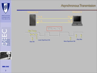
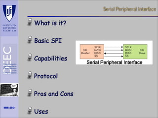
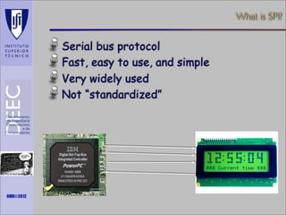
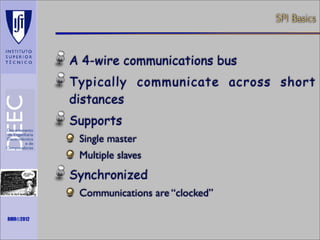
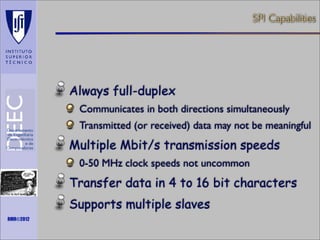
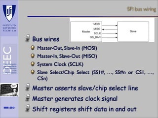
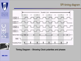
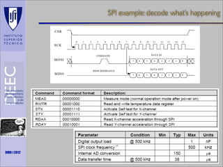
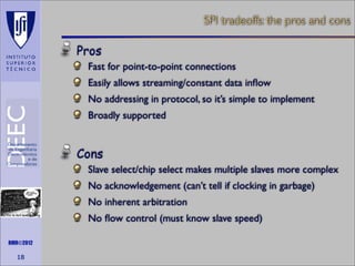
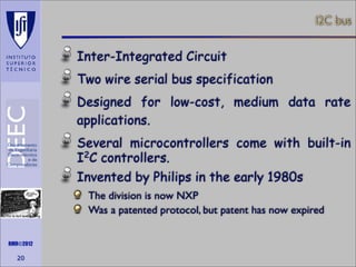
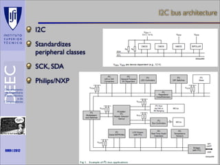
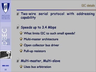
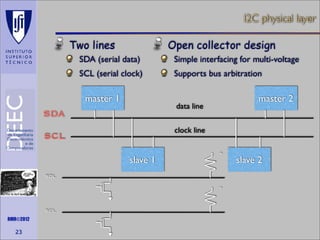
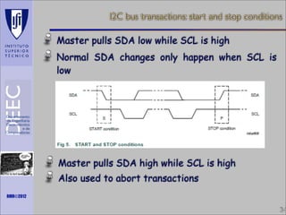
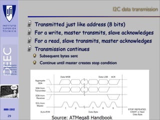
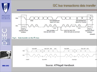
Maths is not everything

Embedded Systems
4 - Hardware Architecture

CPU
Input/Output mechanisms
Memory
Buses and Aux I/O
Input/Output interfaces
RMR©2012

Power Management
Maths is not everything

UART

RMR©2012
Asynchronous Transmission
Máquina B

Máquina A

Tx A
Rx A

Bit Time

Rx B
Tx B

65H

Least Significant Bit
Start Bit

Maths is not everything

RMR©2012

3

‘e’

Stop Bits
Most Significant Bit
DB9 pinout of a DTE

DTE vs DCE
Pinout of a DCE?
Common ground?
Noise effects?

Maths is not everything

RMR©2012
RS-232 transmission example

Maths is not everything

RMR©2012

How do peers agree on timing?
Maths is not everything

SPI

RMR©2012
Serial Peripheral Interface

What is it?
Basic SPI
Capabilities
Protocol
Maths is not everything

RMR©2012

Pros and Cons
Uses

Serial Peripheral Interface
What is SPI?

Serial bus protocol
Fast, easy to use, and simple
Very widely used
Not “standardized”

Maths is not everything

RMR©2012
SPI Basics

A 4-wire communications bus
Typically communicate across short
distances
Supports
Single master
Multiple slaves

Synchronized
Maths is not everything

RMR©2012

Communications are “clocked”
SPI Capabilities

Always full-duplex
Communicates in both directions simultaneously
Transmitted (or received) data may not be meaningful

Multiple Mbit/s transmission speeds
0-50 MHz clock speeds not uncommon

Transfer data in 4 to 16 bit characters
Maths is not everything

RMR©2012

Supports multiple slaves
SPI bus wiring

Bus wires
Master-Out, Slave-In (MOSI)
Master-In, Slave-Out (MISO)
System Clock (SCLK)
Slave Select/Chip Select (SS1#, …, SS#n or CS1, …,
CSn)

Master asserts slave/chip select line
Maths is not everything

RMR©2012

Master generates clock signal
Shift registers shift data in and out
SPI signal functions

MOSI – carries data out of master to slave
MISO – carries data out of slave to master
Both MOSI and MISO are active during every
transmission

Maths is not everything

RMR©2012

SS# (or CS) – unique line to select each
slave chip
SCLK – produced by master to synchronize
transfers
SPI uses a “shift register” model of communications

Master shifts out data to Slave, and shifts in data from Slave

Maths is not everything

RMR©2012
Two bus configuration models

Maths is not everything

RMR©2012

Master and multiple independent
slaves

Master and multiple daisy-chained
slaves
SPI clocking: there is no “standard way”
Four clocking “modes”
Two phases
Two polarities

Master and selected slave must be in the same mode
During transfers with slaves A and B, Master must
Configure clock to Slave A’s clock mode
Select Slave A
Do transfer
Deselect Slave A
Configure clock to Slave B’s clock mode
Maths is not everything

Select Slave B
Do transfer

RMR©2012

Deselect Slave B

Master reconfigures clock mode on-the-fly!
SPI timing diagram

Maths is not everything

RMR©2012

Timing Diagram – Showing Clock polarities and phases
SPI example: decode what’s happening

Maths is not everything

RMR©2012
SPI tradeoffs: the pros and cons

Pros
Fast for point-to-point connections
Easily allows streaming/constant data inflow
No addressing in protocol, so it’s simple to implement
Broadly supported

Cons
Slave select/chip select makes multiple slaves more complex
No acknowledgement (can’t tell if clocking in garbage)
No inherent arbitration
Maths is not everything

RMR©2012

18

No flow control (must know slave speed)
Maths is not everything

I2C

RMR©2012
I2C bus

Inter-Integrated Circuit
Two wire serial bus specification
Designed for low-cost, medium data rate
applications.
Several microcontrollers come with built-in
I2C controllers.
Invented by Philips in the early 1980s
Maths is not everything

RMR©2012

20

The division is now NXP
Was a patented protocol, but patent has now expired
I2C bus architecture
I2C
Standardizes
peripheral classes
SCK, SDA
Philips/NXP

Maths is not everything

RMR©2012
I2C details

Two-wire serial protocol with addressing
capability
Speeds up to 3.4 Mbps
What limits I2C to such small speeds?
Multi-master architecture
Open collector bus driver
Pull-up resistors
Maths is not everything

RMR©2012

22

Multi-master, Multi-slave
Uses bus arbitration
I2C physical layer
Two lines

Open collector design

SDA (serial data)

Simple interfacing for multi-voltage

SCL (serial clock)

Supports bus arbitration

master 1

master 2

data line

SDA

clock line

SCL
slave 1

+

SDL
+
Maths is not everything

SCL
RMR©2012

23

slave 2
I2C signaling

Sender pulls down bus for 0.
Sender listens to bus---if it tried to send
a 1 and heard a 0, someone else is
simultaneously transmitting.

Maths is not everything

RMR©2012

© 2008 Wayne Wolf

Transmissions occur in 8-bit bytes.
I2C clock

Not a “traditional” clock
Normally is kept “high” using a pull-up
Pulsed by the master during data
transmission
Master could be either the transmitter or receiver

Slave device can hold clock low if needs
more time
Allows for flow control
Maths is not everything

RMR©2012

25
I2C transaction

Transmitter/receiver differs from
master/slave
Master initiates transactions
Slave responds

Transmitter sets data on SDL line, slave
acks
Maths is not everything

RMR©2012

26

For a read, slave is transmitter
For a write, master is transmitter
I2C bus transactions: start and stop conditions
Master pulls SDA low while SCL is high
Normal SDA changes only happen when SCL is
low

Master pulls SDA high while SCL is high
Maths is not everything

Also used to abort transactions

RMR©2012

34
I2C address transmission

Data is always sampled on the rising clock
edge
Address is 7 bits
An 8-th bit indicated read or write
High for read
Low for write

Addresses assigned by Philips/NXP
Maths is not everything

For a fee
Was covered by patent

RMR©2012

28
I2C data transmission
Transmitted just like address (8 bits)
For a write, master transmits, slave acknowledges
For a read, slave transmits, master acknowledges
Transmission continues
Subsequent bytes sent
Continue until master creates stop condition

Maths is not everything

RMR©2012

29
I2C bus arbitration

Sender listens while sending address.

Maths is not everything

RMR©2012

© 2008 Wayne Wolf

When sender hears a conflict, if its
address is higher, it stops signaling.
Low-priority senders relinquish control
early enough in clock cycle to allow bit to
be transmitted reliably.
I2C transmissions

multi-byte write
S

adrs

0

data

data

1

data

P

0

data

S

P

read from slave
S

adrs

write, then read

Maths is not everything

RMR©2012

© 2008 Wayne Wolf

S

adrs

adrs

1

data

P
I2C bus transactions: data transfer

Maths is not everything

RMR©2012

S emb t8-arch_itfio

  • 1.
    Maths is noteverything Embedded Systems 4 - Hardware Architecture CPU Input/Output mechanisms Memory Buses and Aux I/O Input/Output interfaces RMR©2012 Power Management
  • 2.
    Maths is noteverything UART RMR©2012
  • 3.
    Asynchronous Transmission Máquina B MáquinaA Tx A Rx A Bit Time Rx B Tx B 65H Least Significant Bit Start Bit Maths is not everything RMR©2012 3 ‘e’ Stop Bits Most Significant Bit
  • 4.
    DB9 pinout ofa DTE DTE vs DCE Pinout of a DCE? Common ground? Noise effects? Maths is not everything RMR©2012
  • 5.
    RS-232 transmission example Mathsis not everything RMR©2012 How do peers agree on timing?
  • 6.
    Maths is noteverything SPI RMR©2012
  • 7.
    Serial Peripheral Interface Whatis it? Basic SPI Capabilities Protocol Maths is not everything RMR©2012 Pros and Cons Uses Serial Peripheral Interface
  • 8.
    What is SPI? Serialbus protocol Fast, easy to use, and simple Very widely used Not “standardized” Maths is not everything RMR©2012
  • 9.
    SPI Basics A 4-wirecommunications bus Typically communicate across short distances Supports Single master Multiple slaves Synchronized Maths is not everything RMR©2012 Communications are “clocked”
  • 10.
    SPI Capabilities Always full-duplex Communicatesin both directions simultaneously Transmitted (or received) data may not be meaningful Multiple Mbit/s transmission speeds 0-50 MHz clock speeds not uncommon Transfer data in 4 to 16 bit characters Maths is not everything RMR©2012 Supports multiple slaves
  • 11.
    SPI bus wiring Buswires Master-Out, Slave-In (MOSI) Master-In, Slave-Out (MISO) System Clock (SCLK) Slave Select/Chip Select (SS1#, …, SS#n or CS1, …, CSn) Master asserts slave/chip select line Maths is not everything RMR©2012 Master generates clock signal Shift registers shift data in and out
  • 12.
    SPI signal functions MOSI– carries data out of master to slave MISO – carries data out of slave to master Both MOSI and MISO are active during every transmission Maths is not everything RMR©2012 SS# (or CS) – unique line to select each slave chip SCLK – produced by master to synchronize transfers
  • 13.
    SPI uses a“shift register” model of communications Master shifts out data to Slave, and shifts in data from Slave Maths is not everything RMR©2012
  • 14.
    Two bus configurationmodels Maths is not everything RMR©2012 Master and multiple independent slaves Master and multiple daisy-chained slaves
  • 15.
    SPI clocking: thereis no “standard way” Four clocking “modes” Two phases Two polarities Master and selected slave must be in the same mode During transfers with slaves A and B, Master must Configure clock to Slave A’s clock mode Select Slave A Do transfer Deselect Slave A Configure clock to Slave B’s clock mode Maths is not everything Select Slave B Do transfer RMR©2012 Deselect Slave B Master reconfigures clock mode on-the-fly!
  • 16.
    SPI timing diagram Mathsis not everything RMR©2012 Timing Diagram – Showing Clock polarities and phases
  • 17.
    SPI example: decodewhat’s happening Maths is not everything RMR©2012
  • 18.
    SPI tradeoffs: thepros and cons Pros Fast for point-to-point connections Easily allows streaming/constant data inflow No addressing in protocol, so it’s simple to implement Broadly supported Cons Slave select/chip select makes multiple slaves more complex No acknowledgement (can’t tell if clocking in garbage) No inherent arbitration Maths is not everything RMR©2012 18 No flow control (must know slave speed)
  • 19.
    Maths is noteverything I2C RMR©2012
  • 20.
    I2C bus Inter-Integrated Circuit Twowire serial bus specification Designed for low-cost, medium data rate applications. Several microcontrollers come with built-in I2C controllers. Invented by Philips in the early 1980s Maths is not everything RMR©2012 20 The division is now NXP Was a patented protocol, but patent has now expired
  • 21.
    I2C bus architecture I2C Standardizes peripheralclasses SCK, SDA Philips/NXP Maths is not everything RMR©2012
  • 22.
    I2C details Two-wire serialprotocol with addressing capability Speeds up to 3.4 Mbps What limits I2C to such small speeds? Multi-master architecture Open collector bus driver Pull-up resistors Maths is not everything RMR©2012 22 Multi-master, Multi-slave Uses bus arbitration
  • 23.
    I2C physical layer Twolines Open collector design SDA (serial data) Simple interfacing for multi-voltage SCL (serial clock) Supports bus arbitration master 1 master 2 data line SDA clock line SCL slave 1 + SDL + Maths is not everything SCL RMR©2012 23 slave 2
  • 24.
    I2C signaling Sender pullsdown bus for 0. Sender listens to bus---if it tried to send a 1 and heard a 0, someone else is simultaneously transmitting. Maths is not everything RMR©2012 © 2008 Wayne Wolf Transmissions occur in 8-bit bytes.
  • 25.
    I2C clock Not a“traditional” clock Normally is kept “high” using a pull-up Pulsed by the master during data transmission Master could be either the transmitter or receiver Slave device can hold clock low if needs more time Allows for flow control Maths is not everything RMR©2012 25
  • 26.
    I2C transaction Transmitter/receiver differsfrom master/slave Master initiates transactions Slave responds Transmitter sets data on SDL line, slave acks Maths is not everything RMR©2012 26 For a read, slave is transmitter For a write, master is transmitter
  • 27.
    I2C bus transactions:start and stop conditions Master pulls SDA low while SCL is high Normal SDA changes only happen when SCL is low Master pulls SDA high while SCL is high Maths is not everything Also used to abort transactions RMR©2012 34
  • 28.
    I2C address transmission Datais always sampled on the rising clock edge Address is 7 bits An 8-th bit indicated read or write High for read Low for write Addresses assigned by Philips/NXP Maths is not everything For a fee Was covered by patent RMR©2012 28
  • 29.
    I2C data transmission Transmittedjust like address (8 bits) For a write, master transmits, slave acknowledges For a read, slave transmits, master acknowledges Transmission continues Subsequent bytes sent Continue until master creates stop condition Maths is not everything RMR©2012 29
  • 30.
    I2C bus arbitration Senderlistens while sending address. Maths is not everything RMR©2012 © 2008 Wayne Wolf When sender hears a conflict, if its address is higher, it stops signaling. Low-priority senders relinquish control early enough in clock cycle to allow bit to be transmitted reliably.
  • 31.
    I2C transmissions multi-byte write S adrs 0 data data 1 data P 0 data S P readfrom slave S adrs write, then read Maths is not everything RMR©2012 © 2008 Wayne Wolf S adrs adrs 1 data P
  • 32.
    I2C bus transactions:data transfer Maths is not everything RMR©2012