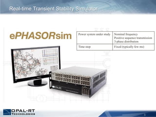
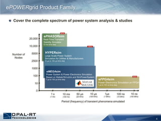
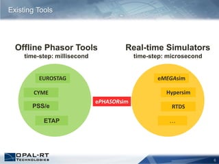
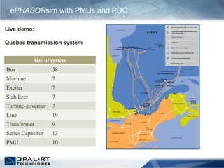
1
From Imagination to Real-Time
ePHASORsim
2
ePHASORsim presentation
– Introduction
– Features
– Applications
– Timeline and future developments
Live demonstration
– The Québec transmission system
Agenda
Real-time Transient Stability Simulator
3
Power system under study Nominal frequency
Positive sequence transmission
3-phase distribution
Time-step Fixed (typically few ms)
4
Cover the complete spectrum of power system analysis & studies
ePOWERgrid Product Family
ePHASORsim
Real-Time Transient
Stability Simulator
10 ms time step
NEW
HYPERsim
Large Scale Power System
Simulation for Utilities & Manufacturers
10 µs to 100 µs time step
NEW
eFPGAsim
Power Electronics Simulation on FPGA
1 µs to 100 ns time step
NEW
1 s
(1 Hz)
10,000
5000
2500
1000
100
10
0
10 ms
(100 Hz)
50 µs
(20 KHz)
10 µs
(100 KHz)
1µs
(1 MHz)
100 ns
(10 MHz)
10 ns
(100 MHz)
20,000
Period (frequency) of transient phenomena simulated
Number of
Nodes
eMEGAsim
Power System & Power Electronics Simulation
Based on Matlab/Simulink and SimPowerSystem
7 µs to 100 µs time step
5
Applications of ePHASORsim
ePHASORsim
for Large-Scale
Power Systems
UDM
Simulation
Hardware-
In-the-Loop
Parallel
Processing
Distribution
Systems
Test
SCADA
Systems
Operator
Training
Simulator
Transient
Stability
Real-time
Simulation
6
Existing Tools
Offline Phasor Tools
time-step: millisecond
PSS/e
ETAP
EUROSTAG
CYME
Real-time Simulators
time-step: microsecond
eMEGAsim
Hypersim
RTDS
…
ePHASORsim
7
Data Entry for ePHASORsim
8
ePHASORsim vs SPS Phasor mode
Features ePHASORsim SPS with Phasor option
Circuit editor Excel spreadsheet or PSS/e v.32 files SPS circuit editor
Interface with external devices Using Simulink Using Simulink
Transmission system Yes Yes
Unbalanced system Yes Yes
Supported components Fundamental models A comprehensive library
Largest system size tested 20k bus, 5k machine 200bus, 28 machine
Compilation time with
eMEGAsim for largest system
45 s 32m:42s
Load time with eMEGAsim less than 5 seconds few seconds
Number of CPU cores 1 9
Just opening the model in
Matlab (offline)
Normal 4 mins
Facility to split the system Not implemented yet, but there is no
limitation
There must be long lines, or a
transformer with stub-line. It needs
compensation. SSN blocks do not
work in SPS Phasor mode
Manual change of parameters
during simulation
All parameters are accessible There are limitations
9
Performance of ePHASORsim
Simulation time: 10s, time-step: 10ms
Number of CPU cores: 1
Case 1 Case 2 Case 3
Number of
components
Buses 4992 9984 19968
Generators 1280 2560 5120
Controllers 2304 4610 9216
Others 9144 18368 36820
Computation
time (ms)
Normal 1.62 3.28 6.68
Disturbance 3.49 7.43 16.61
Overruns NO NO YES
1. Large-scale power systems in Real-time
• 10,000 buses on-fly
2. Open and scalable hardware platform
• Integrated with a chassis equipped with FPGA and I/Os
• Interfaced with communication protocols such as IEC61850,
DNP3 (+-10ms), C37.118, OPC (+-100ms)
3. Test automation platform
• Perform test automation using Python scripts
• Use ScopeView to record, display and analyze results
• Interfaced with LabView to implement realistic control panels
• Modify parameters while the simulation is running
Features
4. Third-party connectivity
• Interfaced with Simulink, SimPowerSystems and SimScape to
enable users to develop their own load, control and protection
models
• Interface with the Excel™ spreadsheet and with PTI’s PSS/e to
import the network data files
Features
ePHASORsim with DNP3 and IOs
ePHASORsim
ePHASORsim and EMT
0 (No External PSS)
1 (External PSS)
0 (UDM PSS)
1 (SPS PSS)
1
Out1
Line Out/In
Load Out/In
Bus Fault
Vref
M
area1
2(s+1)
(s+2)
Zero-Pole1
s
(s+0.10)
Zero-Pole
speed
Goto2
ExternalDevice PSSmodel
In Vstab
Generic
Power System Stabilizer
2
Gain
speed
ExternalDevice
ExternalDevice
PSSmodel
0
External PSS Type
1
External PSS
0
Constant2
0
Constant1
<speed>
ePHASORsim and UDM with SPS blocks
ePHASORsim with PMUs and PDC
Live demo:
Quebec transmission system
Size of system
Bus 38
Machine 7
Exciter 7
Stabilizer 7
Turbine-governor 7
Line 19
Transformer 9
Series Capacitor 13
PMU 10
Timeline
2010
Project started
2011
First demo (HQ), simulation for
operator training
Distribution system components added
1st client delivery (GE-DTE)
2012
2013
API for externally coded modules
Standalone ePHASORsim,
integrated with new I/O server2014
Parallel ePHASORsim
New components
The future
• Several topics have been identified as important, but
require further analysis:
– GUI
– Import from / export to other formats (e.g. CIM)
– Interface with other software (e.g. ETAP)
– HYPERSIM integration
– Mixed-mode simulations (EMT + Phasor)
Conclusion
• ePHASORsim is a phasor-mode, real-time simulator of
large-scale transmission and distribution systems
• high performance
• flexible
• extensible
• We demonstrated the advantages of ePHASORsim in
various scenarios:
– External control prototyping
– Test SCADA system
– Hybrid simulation
– and more
ePHASORsim with PMUs and PDC
Live demo:
Quebec transmission system
Size of system
Bus 38
Machine 7
Exciter 7
Stabilizer 7
Turbine-governor 7
Line 19
Transformer 9
Series Capacitor 13
PMU 10
Models
Generator, Voltage source
Load (ZIP)
Transmission line
Excitation system
Power System Stabilizer
Turbine-Governor
Transformer (with Tap-Changer)
Reactor
Capacitor banks
External Simulink Blocks
(UDM)
External SPS Controller Blocks
ePHASORsim Library
Events and Actions
Balanced and unbalanced faults
Open-connector conditions
Transmission line trip
Faults on transmission line
section
Generator outage
Load shedding/restoration
Tap-changer adjustment
AVR adjustment
Reclosing commands
Loss of excitation
…

Opal rt e phaso rsim_2013

  • 1.
    1 From Imagination toReal-Time ePHASORsim
  • 2.
    2 ePHASORsim presentation – Introduction –Features – Applications – Timeline and future developments Live demonstration – The Québec transmission system Agenda
  • 3.
    Real-time Transient StabilitySimulator 3 Power system under study Nominal frequency Positive sequence transmission 3-phase distribution Time-step Fixed (typically few ms)
  • 4.
    4 Cover the completespectrum of power system analysis & studies ePOWERgrid Product Family ePHASORsim Real-Time Transient Stability Simulator 10 ms time step NEW HYPERsim Large Scale Power System Simulation for Utilities & Manufacturers 10 µs to 100 µs time step NEW eFPGAsim Power Electronics Simulation on FPGA 1 µs to 100 ns time step NEW 1 s (1 Hz) 10,000 5000 2500 1000 100 10 0 10 ms (100 Hz) 50 µs (20 KHz) 10 µs (100 KHz) 1µs (1 MHz) 100 ns (10 MHz) 10 ns (100 MHz) 20,000 Period (frequency) of transient phenomena simulated Number of Nodes eMEGAsim Power System & Power Electronics Simulation Based on Matlab/Simulink and SimPowerSystem 7 µs to 100 µs time step
  • 5.
    5 Applications of ePHASORsim ePHASORsim forLarge-Scale Power Systems UDM Simulation Hardware- In-the-Loop Parallel Processing Distribution Systems Test SCADA Systems Operator Training Simulator Transient Stability Real-time Simulation
  • 6.
    6 Existing Tools Offline PhasorTools time-step: millisecond PSS/e ETAP EUROSTAG CYME Real-time Simulators time-step: microsecond eMEGAsim Hypersim RTDS … ePHASORsim
  • 7.
    7 Data Entry forePHASORsim
  • 8.
    8 ePHASORsim vs SPSPhasor mode Features ePHASORsim SPS with Phasor option Circuit editor Excel spreadsheet or PSS/e v.32 files SPS circuit editor Interface with external devices Using Simulink Using Simulink Transmission system Yes Yes Unbalanced system Yes Yes Supported components Fundamental models A comprehensive library Largest system size tested 20k bus, 5k machine 200bus, 28 machine Compilation time with eMEGAsim for largest system 45 s 32m:42s Load time with eMEGAsim less than 5 seconds few seconds Number of CPU cores 1 9 Just opening the model in Matlab (offline) Normal 4 mins Facility to split the system Not implemented yet, but there is no limitation There must be long lines, or a transformer with stub-line. It needs compensation. SSN blocks do not work in SPS Phasor mode Manual change of parameters during simulation All parameters are accessible There are limitations
  • 9.
    9 Performance of ePHASORsim Simulationtime: 10s, time-step: 10ms Number of CPU cores: 1 Case 1 Case 2 Case 3 Number of components Buses 4992 9984 19968 Generators 1280 2560 5120 Controllers 2304 4610 9216 Others 9144 18368 36820 Computation time (ms) Normal 1.62 3.28 6.68 Disturbance 3.49 7.43 16.61 Overruns NO NO YES
  • 10.
    1. Large-scale powersystems in Real-time • 10,000 buses on-fly 2. Open and scalable hardware platform • Integrated with a chassis equipped with FPGA and I/Os • Interfaced with communication protocols such as IEC61850, DNP3 (+-10ms), C37.118, OPC (+-100ms) 3. Test automation platform • Perform test automation using Python scripts • Use ScopeView to record, display and analyze results • Interfaced with LabView to implement realistic control panels • Modify parameters while the simulation is running Features
  • 11.
    4. Third-party connectivity •Interfaced with Simulink, SimPowerSystems and SimScape to enable users to develop their own load, control and protection models • Interface with the Excel™ spreadsheet and with PTI’s PSS/e to import the network data files Features
  • 12.
    ePHASORsim with DNP3and IOs ePHASORsim
  • 13.
  • 14.
    0 (No ExternalPSS) 1 (External PSS) 0 (UDM PSS) 1 (SPS PSS) 1 Out1 Line Out/In Load Out/In Bus Fault Vref M area1 2(s+1) (s+2) Zero-Pole1 s (s+0.10) Zero-Pole speed Goto2 ExternalDevice PSSmodel In Vstab Generic Power System Stabilizer 2 Gain speed ExternalDevice ExternalDevice PSSmodel 0 External PSS Type 1 External PSS 0 Constant2 0 Constant1 <speed> ePHASORsim and UDM with SPS blocks
  • 15.
    ePHASORsim with PMUsand PDC Live demo: Quebec transmission system Size of system Bus 38 Machine 7 Exciter 7 Stabilizer 7 Turbine-governor 7 Line 19 Transformer 9 Series Capacitor 13 PMU 10
  • 16.
    Timeline 2010 Project started 2011 First demo(HQ), simulation for operator training Distribution system components added 1st client delivery (GE-DTE) 2012 2013 API for externally coded modules Standalone ePHASORsim, integrated with new I/O server2014 Parallel ePHASORsim New components
  • 17.
    The future • Severaltopics have been identified as important, but require further analysis: – GUI – Import from / export to other formats (e.g. CIM) – Interface with other software (e.g. ETAP) – HYPERSIM integration – Mixed-mode simulations (EMT + Phasor)
  • 18.
    Conclusion • ePHASORsim isa phasor-mode, real-time simulator of large-scale transmission and distribution systems • high performance • flexible • extensible • We demonstrated the advantages of ePHASORsim in various scenarios: – External control prototyping – Test SCADA system – Hybrid simulation – and more
  • 19.
    ePHASORsim with PMUsand PDC Live demo: Quebec transmission system Size of system Bus 38 Machine 7 Exciter 7 Stabilizer 7 Turbine-governor 7 Line 19 Transformer 9 Series Capacitor 13 PMU 10
  • 20.
    Models Generator, Voltage source Load(ZIP) Transmission line Excitation system Power System Stabilizer Turbine-Governor Transformer (with Tap-Changer) Reactor Capacitor banks External Simulink Blocks (UDM) External SPS Controller Blocks ePHASORsim Library Events and Actions Balanced and unbalanced faults Open-connector conditions Transmission line trip Faults on transmission line section Generator outage Load shedding/restoration Tap-changer adjustment AVR adjustment Reclosing commands Loss of excitation …