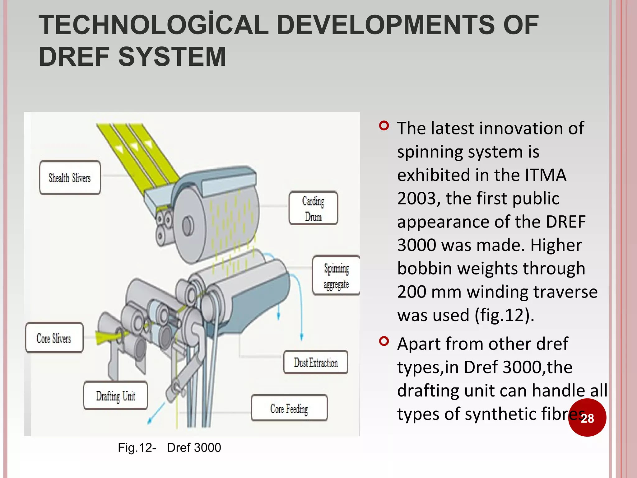
Dref system is Dref 3000
which was introduced in
2003.It has higher
production capacity than
Dref 2000.
This document discusses friction spinning, also known as Dref spinning. It is a textile technology suitable for spinning coarse yarn counts and technical core-wrapped yarns. Dref yarns have low tensile strength, making them suitable for blankets, mops, and filters. The technology was developed in 1975 and allows yarns like rayon and Kevlar to be spun. Friction spinning uses two friction surfaces to roll fibers into yarn with very little tension applied. This makes it more productive than other spinning methods like ring and rotor spinning. Developments
slides CapTechTalks Webinar May 2024 Alexander Perry.pptx
FRICTION SPINNING TECHNOLOGY, (M.S)
1. TE 550 NEW METHODS OF YARN
PRODUCTION
FRICTION SPINNING
1
SUBMITTED TO : PROF.DR.ALİ KİRECCİ
SUBMITTED BY: AYBALA ÖZCAN
DEPARTMENT: TEXTILE TECHN. BY
TEXTILE ENG.
4. FRICTION SPINNING
Features Of Friction Spinning
Yarn properties: low tensile strength
Good uniformity,high production rates
Application: yarns for knitting; terry yarns; weft yarns
Advantages: low manufacturing cost; possibility for automation;
no fast-moving parts
Features: up now no limited application possibilities; delivery
speed is independent from yarn count
Low energy expenses and low labor
4
7. Principle Of Friction (DREF) Spinning Systems
The friction spinning system consists of;
opening & individualization of fibres from slivers,
reassembling of individualized fibres ( collecting),
twisting (imparting the strength by twisting),
withdrawing newly yarn formation,
winding of yarn. ( a cross-wound package)
7
8. SCHEMATIC VIEW OF FRICTION SPINNING SYSTEM
Following
process line
8
Fig.1-SchematicView of Friction Spinning
9. Basic Working Principle Of Friction (Dref) Spinning
1-opened
fibers
2-roller
3-rotating drums
The figure 2 describes the
DREF spinning principle
where the opened fibres
(1) made roll with an aid
of a mechanical roller (2)
for reassembling and
twisting.
Fig.2-Individualizing of fibers on the drums
Fibers are delivered onto the drum surface (3), which
transports and stacks the fibers to the fiber bundle
rotating between two surfaces moving in opposite
directions in fig.1.
9
10. Basic Working Principle of Friction (DREF) Spinning
Fig.1-SchematicView of Friction Spinning
Collected drums
4
1
2
3
•
•
Friction spinning uses two friction surfaces to roll up fibres into a yarn.
The fibres flow freely to two rotating friction drums (3) (spinning
drums, friction rollers, torque rollers).
10
• The surfaces at the nip of the two drums (4) move in opposite direction
to twist the fibres collected in the nip.
12. Basic Working Principle of Friction Spinning
The twisting rate in friction spinning is related to the drum rpm, drum
diameter and yarn diameter as indicated below.
Because of the very large ratio between the drum and yarn diameters,
the rotational speed of the drums need not be high, provided adequate
twist efficiency is achieved.
The twist efficiency is reduced due to the slippage between the yarn in
the nip and the drum surfaces. It is possible to have a twist efficiency as
low as 40%. But even allowing for this, friction spinning is still the most
efficient way of inserting twist to fibres, because twist is directly applied
12
to yarn end.
13. YARN FORMATİON İN FRİCTİON
SPİNNİNG SYSTEM
The mechanism of yarn formation is quite complex. It
consists of three distinct operations, namely:
Feeding
of fibers,
Fibers integration
Twist insertion.
13
14. YARN FORMATİON İN FRİCTİON SPİNNİNG
SYSTEM
1-FEEDING
The individualized fibers are transported by air currents
and deposited in the spinning zone.
The mode of fiber feed has a definite effect on fiber extent
and fiber configuration in yarn and on its properties.
There are two methods of fibre feed :
a)Direct feed
b)Indirect feed.
14
15. YARN FORMATİON İN FRİCTİON SPİNNİNG SYSTEM
FEEDING
In case of direct feed, fibers are fed directly (b) or forward guidance onto the
rotating fiber mass that outer part of the yarn tail.
In indirect feed (c ) or bacward guidance, fibers are first accumulated on the ingoing roll and then transferred to the yarn tail. Figure 3 (b) and (c) are
showing the above methods of fiber feed.
15
Fig.3-Direct and Indirect Fiber Feeding Methods
16. YARN FORMATİON İN FRİCTİON SPİNNİNG
SYSTEM
2-FIBERS INTEGRATION:
The fiber orientation is highly dependent on the decelerating
fibers arriving at the assembly point through the turbulent
flow.
The fibers in the friction drum have two probable methods for
integration of incoming fibres to the sheath.
One method, the fiber assembles completely on to
perforated drum before their transfer to the rotating sheath.
In the other method, fibers are laid directly on to rotating
16
sheath.
17. YARN FORMATİON İN FRİCTİON SPİNNİNG
SYSTEM
3-TWIST INSERTION:
In friction spinning, the fibers are applied twist with more or
less one at a time without cyclic differentials in tension in
the twisting zone.
Therefore, fiber migration may not take place in friction spun
yarns.
The mechanism of twist insertion for core type friction
spinning and open end friction spinning are different,which
are described next slayt.
17
18. YARN FORMATİON İN FRİCTİON SPİNNİNG
SYSTEM
TWIST INSERTION:
a-In Core Type Friction Spinning
Core is made of a filament or a bundle of staple fibers is false
twisted by the spinning drum.
The sheath fibers are deposited on the false twisted core
surface and are wrapped helically over the core with varying
helix angles.
It is believed that the false twist in the core gets removed
once the yarn is emerged from the spinning drums, so that
this yarn has virtually twist less core.
18
19. YARN FORMATİON İN FRİCTİON SPİNNİNG
SYSTEM
TWIST INSERTION:
b-In Open End Type Friction Spinning
The fibers in the yarn are integrated as stacked cone.
The fibers in the surface of the yarn found more compact and
good packing density than the axial fibres in the yarn.
The Figure 4 shown the arrangement of fibers in the DREF-3 yarn
as stacked cone shape .
19
20. COMPARE WITH RING SPINNING AND ROTOR
SPINNING..
Unlike ring spinning and rotor spinning, friction spinning
imposes very little tension to the yarn.
So the ends-down rate in friction spinning is very low and the
yarn can be withdrawn from the nip of the drums at a very
high speed, say 300 m/min. This makes friction spinning
more productive than ring and rotor spinning.
Similar to rotor spinning, friction spinning uses sliver feed
and tooth drafting.
20
21. DEVELOPMENT CATEGORİES OF FRİCTİON
SPİNNİNG
DREF-1
DREF-2
DREF-3
DREF-5
DREF-2000
DREF-3000
21
22. TECHNOLOGİCAL DEVELOPMENTS OF
DREF SYSTEM
‘Dref’ is the trade name given to the machine based on friction spinning
system, which was developed by Dr E Fehrer of Austria. This process is
primarily suited to spin coarser and recycled yarns but most suitable to spin
technical yarn. Today, Dref is only spinning machine, which got commercial
success.
The different versions of the machine are DREF-1, DREF-2, DREF-3, DREF5, DREF-2000 and DREF-3000. DREF-1 friction spinning system has single
friction drum (fig.5), where as DREF-2 has two friction drums (fig.6).
22
Fig.5-Dref-1Schematic Fig. (Single Drum)
Fig.6-Dref-2 Schematic Fig. (Double Drum)
23. TECHNOLOGİCAL DEVELOPMENTS OF
DREF SYSTEM
Dref-2 is one of the earliest friction spinning machines introduced in the market
somewhere around 1977 primarily for long staple fibers to produce coarser yarns
was exhibited in the year 1975 at ITMA exhibition.
Dr Ernst Fehrer began work on the development of the DREF 3 friction spinning
system, which was first presented to the public at the 1979 international textile
machinery exhibition (ITMA'79) in Hanover.
Dref-3 is a development over of Dref-2 system for improving the quality of
yarn,productivity and count range came to the market in the year 1981,and this is a
core-sheath type spinning arrangement and produce component yarns which can
not be produce by other spinning machines(Fig.7-Dref 3 ).
Fig.7-Dref-3 Process
Schema
23
24. Technological Developments Of Dref System
Dref -2 End-Uses Areas
Blankets
for the homes, hotels, hospitals, camping, military uses, plaids etc.
Cleaning rags and mops from cotton waster and various waste-blends
Deco- and upholstery fabrics (fig.8)
Outerwear and leisure-wear
Filter cartridges for liquid filtration
Secondary carpet backing for tufting carpets
Canvas and tarpaulins for the military and civil sectors
Fif.8-upholstery fabrics
High-tenacity core yarn for ropes, transport and conveyor belts
Asbestos substitutes for heavy protective clothing (protective gloves, aprons
etc) packing, gaskets, clutch and brake-linings, flame retardant fabrics etc.
Filter yarns for the cable, shoe and carpet industries
Carpet Yarns (Berber carpets, hand-woven and hand-knotted carpets) and filler
weft yarns for carpets.
24
25. TECHNOLOGİCAL DEVELOPMENTS OF
DREF SYSTEM
Dref 5 was developed by
Schalafhorst, Suessen and Fehrer
after Dref 3,but this spinning
system was not commercialized
due to to various technical
difficulties.
In 1999 ,Dref 2000 was
demonstrated at ITMA exhibition
(fig.9).
It has ‘S’ and ‘Z’ direction is
possible without mechanical
alterations to the machine.And this
machine also has dust extraction
for secondary fibers and low
energy costs due to the use of only
Fig.9-Dref 2000
25
26. TECHNOLOGİCAL DEVELOPMENTS OF
DREF SYSTEM
Dref-3 spinning system has
advantages over Dref-2 which
are;
oThe sheath fibers are attached
to the core fibers by the false
twist generated by the rotating
action of drums.[fig.10]
oTwo drafting units are used in
this system, one for the core
fibers and other for the sheath
fibers
26
Fig.10-Dref-3 Schematic Figure
27. TECHNOLOGİCAL DEVELOPMENTS OF
DREF SYSTEM
Dref 2000 End-Uses Areas
Blankets
for the homes, hotels, hospitals, camping,
military uses, plaids etc.
Deco- and upholstery fabrics
Outerwear and leisure-wear
Filter cartridges for liquid filtration
Secondary carpet backing for tufting carpets (fig.11)
Canvas and tarpaulins for the military and civil sectors
High-tenacity core yarn for ropes, transport and
conveyor belts
Asbestos substitutes for heavy protective clothing
(protective gloves, aprons etc) packing, gaskets, clutch
and brake-linings, flame retardant fabrics etc.
Filter Yarns for the cable, shoe and carpet industries
Carpet Yarns (Berber carpets, hand-woven and handknotted carpets) and filler weft yarns for carpets. (fig.9)
Fig.11-Dref 2000 end
uses,Gloves and
secondary carpet
backing yarns,TBA
Textiles
27
28. TECHNOLOGİCAL DEVELOPMENTS OF
DREF SYSTEM
Fig.12- Dref 3000
The latest innovation of
spinning system is
exhibited in the ITMA
2003, the first public
appearance of the DREF
3000 was made. Higher
bobbin weights through
200 mm winding traverse
was used (fig.12).
Apart from other dref
types,in Dref 3000,the
drafting unit can handle all
types of synthetic fibres.
28
29. TECHNOLOGİCAL DEVELOPMENTS OF DREF
SYSTEM
Dref 3000 End UsesArea
Backing
fabrics for printing, electrical
insulation, hoses, filter fabrics
Hot air filtration and wet filtration in food
and sugar industries.
Clutch lining and brake lining for
automotive industries.(fig.13)
Fire resistant protecting clothing,aircraft
and contract carpeting,
Conveyor and transport belts.
Composites for aviaton and automotive
industries.
Fig.13-Brake linings for
auotomotive industry produced
by Dref 3000 method.
29
30. TECHNOLOGİCAL DEVELOPMENTS OF
DREF SYSTEM
Dref 3000 spinning system has a drafting unit can handle all types of synthetic
fibres such as;
aramid, FR and pre-oxidized fibres, polyamides, glass fibers in blends
phenol resin fibres (e.g. Kynol), melamine fibres (e.g. Basofil), melt fibres (e.g.
PA, PES, PP),
natural fibres (wool, cotton, jute, linen, flax, etc.),
Dref 3000 has some advantages over other friction systems ;
Production of both ‘S’ and ‘Z’ yarns at any time without mechanical
alterations to the machine.
Reduced yarn preparation costs due to high sliver weights (card slivers)
Higher Bobbin weights through 200mm winding traverse.
DREF 3000 core yarns offer high output, breakage-free spinning and weaving
mill operation and thus up to 95% efficiency can be achieved.
30
31. SPINNING TENSION FOR DREF YARNS
Friction spun yarns have less spinning tension during the yarn
formation.(Fig.14)
Due to less tension during the spinning the core component can be
placed exactly at the centre of the yarn.
Fig.14-Spinning Tension for DREF Ring and Rotor Yarns
31
32. PROPERTIES OF FRICTION SPUN YARNS
Friction spun yarns (DREF) yarns have bulky appearance (100-140%
bulkier than the ring spun yarns).
The twist is not uniform and found with loopy yarn surface.
Usually weak as compared to other yarns.
The yarns possess only 60% of the tenacity of ring-spun yarns and
about 90% of rotor spun-yarns.
The breaking elongation of ring, rotor and friction spun yarns is equal.
32
33. PROPERTİES OF FRİCTİON SPUN YARNS
Depending on the type of fiber, the differences in strength of these
yarns differ in magnitude.
100% polyester yarns-strength deficiency is 32%
100% viscose yarns-it ranges from 0-25%
In polyester-cotton blend, DREF yarns perform better than their ringspun counterparts.
70/30% blend yarn-superior in strength by 25%
DREF yarns are inferior in terms of unevenness, imperfections,
strength variability and hairiness.
The friction spun yarns are more hairy than the ring spun yarns
DREF yarns are most irregular in terms of twist and linear density
while ring spun yarns are most even.
33
34. PROPERTIES OF HYBRID YARNS/DREF CORE
YARNS
If one yarn creates out of 2 or more single
yarn components is called hybrid yarn.
Hybrid yarns are used;
For reinforced plastic (fig.15)
Yarn Properties
Core/Sheath structure with
centric position of the reinforcing
filament
Zero twisted reinforced filament
gives best strength result
Definable fiber matrix proportion
Protection of the reinforcing
filament through the sheath
fibers
Fig.15-Reinforced plastics
produced by dref method used
hybrid yarn
34
35. HYBRİD YARNS/DREF CORE YARNS
For liquid filter cartridges (fig.16)
Yarn Properties
Huddle fiber arrangement for best filter action
High elongation values
Long yarn length knotless
Uniform yarn with high tensile strength
For heat proof woven and knitted fabrics (fig.17)
Yarn properties
Flame resistance
High temperature resistance
High tear abrasion resistance
Good wearing comfort
Good care properties
Skin friendly
Fig.16-Liquid filter cartridges
Fig.17-Fire gloves
,nonflammable
woven hybrid fabric
produce by friction
method..
35
36. HYBRİD YARNS/DREF CORE YARNS
For Secondary carpet backings(fig.18)
Yarn Properties
Steady high tensile strength
High uniformity of the yarn
Long knotless length of the yarn
Good non-rotating properties
High chemical resistance
Good thermal transfer
Dust free product
Electric insulation
Good dimension stability for carpets
Fig.18-Secondary backing
fabric of tufted carpet.
36
37. HYBRİD YARNS/DREF CORE YARNS
For asbestos substitute (fig.19)
Yarn properties
High yarn volume
Good temperature resistance
High tensile strength
Low elongation
Cut proof woven and knitted fabric
(fig.20)
Yarn properties
High cut resistance
Good wearing comfort
High dimension stability
Fig.19-Ropes and Fabrics which are
used marine produces by asbestos
by frictipn method.
Fig.20-Cut –roof gloves
37
38. ADVANTAGES OF FRICTION SPINNING
SYSTEM
Greater flexibility of processing a wide range of fibres.
Higher production speed (up to 500 mpm).
Ability to produce multi component and hollow yarns.
Ability to generate huge no of turns per unit length of yarn
with one revolution of twisting element.
The number of end-breaks in friction spinning is quite low,
which results in higher machine efficiency than ring and rotor
spinning.
Rewinding is eliminated.
Bulkier and softer handle than that of ring and rotor spun yarn
38
39. LIMITATIONS OF FRICTION SPINNING SYSTEM
Low yarn strength and extremely poor fiber orientation made the
friction spun yarns very weak.
The extent of disorientation and buckling of fibers are predominant
with longer and finer fibers.
Friction spun yarns have higher snarling tendency.
High air consumption leads to high power consumption.
The twist variation from surface to core is quite high; this is another
reason for the low yarn strength.
It is difficult to hold spinning conditions as constant.
The spinning system is limited by drafting and fiber transportation
speeds.
39
40. İN COMPARİSİON WİTH OTHER SPİNNİNG
SYSTEMS
Friction spun yarns are usually weaker than other yarns due its structural
weakness. It has been demonstrated that DREF-2 friction spun yarns possess
only 60% of the tenacity of ring spun yarns and about 90% of that of rotor
spun yarn.
It has also shown that friction spun yarn generally has
*60 - 70% strength,
*60 - 90% unevenness,
*100 - 140% bulk and
*requires 75 - 100% of the minimum no of fibres
in the cross section as compared with the corresponding ring spun yarn.
Rotor spun yarns show the highest evenness followed by ring spun and
friction spun yarns.
The imperfections were also less in friction spun yarns than in rotor spun
40
yarns but higher than those in ring spun yarns.
41. İN COMPARİSİON WİTH OTHER SPİNNİNG
SYSTEMS
Further friction spun yarns are more hairy than ring or rotor yarns and are
more susceptible to stripping back and thus abrading easily.
In respect of yarn to metal friction, ring spun yarn exhibits the highest
friction, followed by rotor and friction spun yarns for cotton and viscose
fibres. With polyester fibre, friction spun yarns show the highest value of
friction followed by rotor and ring spun yarns.
DREF-3 yarns occupy an intermediate position between ring and rotor
spun yarns as far as short hair (up to 3 mm) and total hairiness were
concerned.
In addition DREF-3 yarns are the most irregular in terms of twist and
linear density unevenness, and ring spun yarns are most even.
DREF-3 yarns also show a lower resistance to abrasion and repeated
extensions than ring and rotor spun yarns.
Further the twist level did not have any influence on the rigidity of ring
and rotor spun yarns. But the flexural rigidity of DREF-3 yarns decreased41
considerably with increasing twist.
42. REFEFERENCES
1-Wang X, Huang W and Huang XB, 1999, A study on the formation of yarn hairiness,
Journal of the Textile Institute, 90 Part 1, No 4, p.555 - 569.
2-Grosberg, P. and Iype, C., Yarn production - Theoretical aspects, The Textile Institute,
Manchester, 1999.
3-Klein, W., Manual of textile technology Vol 5: New spinning systems, The Textile
Institute, Manchester, 1993, p.14.
4-Wulfhorst, B., Evaluation of the new spinning techniques on automation and quality
criteria, ITB - Yarn Forming, No. 4, 1990, p. 5 - 13.
5-http://textlnfo.wordpress.com/2011/11/12/dref-spinning/
6- http://textile2technology.com/2009/10/dref-3-yarn-frictional-behaviour.html
7-Friction Spinning-A Critical View ,N.Balasubramanian,The Bombay Research Textile
Association,L.B.S Marg,Ghatkopar (West),Bombay 400 088,13 April 1992.
8-Experimental Study of the Frictional Properties of Friction Spun Yarns, S. S.
Ramkumar,* L. Shastri, R. W. Tock, D. C. Shelly, M. L. Smith, S. Padmanabhan,Texas Tech
University, Lubbock, Texass,29 August 2002.
9- http://www.indiantextilejournal.com/articles/FAdetails.asp?id=4636
42