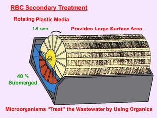
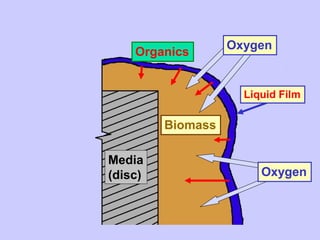
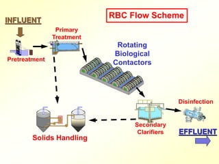
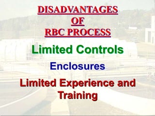
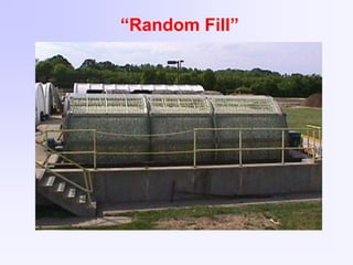
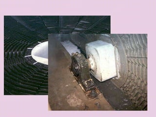
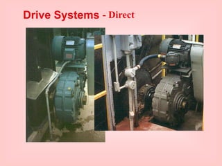
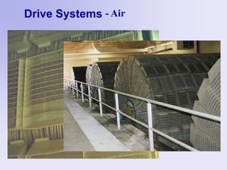
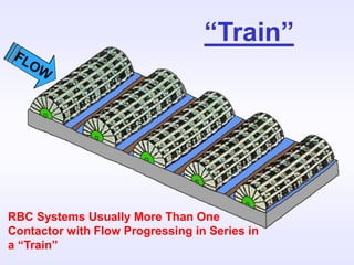
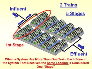
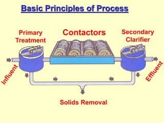
ROTATING BIOLOGICAL
CONTACTOR (RBC)
PROCESS
Prepared By
Michigan Department of Environmental Quality
Operator Training and Certification Unit
ROTATING
BIOLOGICAL
CONTACTORS
Influent Effluent
Primary
Treatment
Secondary
Clarifier
Contactors
Solids Removal
RBC Secondary Treatment
Plastic Media
1.6 rpm
40 %
Submerged
Microorganisms “Treat” the Wastewater by Using Organics
Provides Large Surface Area
Rotating
Food
Storage
Slime Layer
New Cells
Oxygen
Soluble Organics
Cell
Membrane
NH3
CO2
H2O
Adsorbed
Particle
Enzymes
Wastewater
(Absorption)
Biomass
Media
(disc)
Organics
Oxygen
Liquid Film
Oxygen
Organics
Liquid Film
Liquid Film
Media
BIOMASS
Random
Continuous
Sloughing
Pretreatment
Primary
Treatment
Rotating
Biological
Contactors
Secondary
Clarifiers
Solids Handling
INFLUENT
Disinfection
EFFLUENT
RBC Flow Scheme
ADVANTAGES OF RBC PROCESS
Simple Operation
Low Energy Requirements
Nitrification
Wide Flow Range
Few Nuisances
Large Biological Population
ADVANTAGES OF RBC PROCESS
Simple Operation
Low Energy Requirements
Nitrification
Wide Flow Range
Handles Shock Loads
Few Nuisances
Low Head Loss
Large Biological Population
DISADVANTAGES
OF
RBC PROCESS
Limited Controls
Enclosures
Limited Experience and
Training
RBC COMPONENTS
TANK
CONTACTOR
CLARIFIER
RBC COMPONENTS
CONTACTOR
Shaft
Individual Disc
Discs
Media “High Density” Polyethylene
Carbon
Black
Media – Irregular Surface
Maintain Spacing
Increases Rigidity
Increases Surface Area
Increases Contact Time
Media – Irregular Surface
“Corrugated”
Media – Irregular Surface
“Dimpled”
“Random Fill”
Media
BIOMASS
1 Inch
10 to 12 Ft
Diameter
~ 25 Ft
Long
Media
Standard
Density
High
Density
1 inch ¾ inch
Square Shaft
Shaft
Round Shaft
Octagonal Shaft
Bearings
“Floating”
Self-aligning
Bearings
Load Cells
Shaft
Bearing
Load
Cell Coupling for
Hydraulic
Pump
Load Cells
Purpose: Determine Weight of Contactor to
Determine Amount (Thickness) of Biomass
Drive Systems - Chain
Drive Systems - Direct
Drive Systems - Air
Air Cups
Air Diffusers
Air
Header
Air Cups
Air Header
Drive Systems - Air
Drive Systems - Air
Drive Systems - Air
Drive Systems - Combination
Containment
Just Large Enough
Containment
Good Contact
Minimal Short Circuiting
Good Mixing
“Train”
RBC Systems Usually More Than One
Contactor with Flow Progressing in Series in
a “Train”
Parallel to Shaft
Perpendicular to Shaft
Direction of Flow
Flow Schemes
Contactors May be Arranged With Flow Either
Parallel or Perpendicular to Shafts
Influent
Effluent
Baffles
“Train” Small Systems – Train May be One
Contactor with Separations and Baffles
Influent
Effluent
Baffles
Enclosure
Larger Systems – Contactors are Set in Series
in Separate Tanks or in One Tank With
Baffles
Baffles
Train
Baffles Separate Each Contactor,
Dividing the Flow in the Train Into Separate
Complete Mix Zones of Treatment
Baffles
Train
Each Zone of Treatment is Called a
“Stage”
Baffles
Train
Stages
5
(Zones of Treatment)
2 Trains
5 Stages
1st Stage
Effluent
Influent
When a System Has More Than One Train, Each Zone in
the System That Receives the Same Loading is Considered
One “Stage”
BOD, mg/L
100
60
39
25
18
STAGING
Staging Results in Significantly More
Efficient Treatment
STAGING
This Especially Important for Facilities that are
Required Nitrify Ammonia
Pretreatment
Primary
Treatment
Rotating
Biological
Contactors
Secondary
Clarifiers
Solids Handling
INFLUENT
Disinfection
EFFLUENT
RBC Flow Scheme
Sludge
Removal
Scum Removal
Secondary Clarifier
Clarifier
Chemical Phosphorus Removal
Sludge Removal
500 to 800 gpd/sq.ft.
Enclosures
Ultraviolet Light
Hard Rains
Freezing
Algae
Protect Contactors
Equipment
Security
Enclosures
Roof Only
Prefabricated Covers
Permanent Building
Types of Structures
Enclosures Prefabricated
Covers
Enclosures Permanent Building
Enclosures
Ventilation
Humidity Control
Heat Loss
Observation
Operational Considerations
Maintenance
Basic Principles of Process
Primary
Treatment
Secondary
Clarifier
Contactors
Solids Removal
“LOADING”
Amount Applied
to the
Treatment Process
(Related to the SIZE of the System)
Hydraulic Loading
Amount of Liquid
Volume (gallons)
Organic Loading
Amount of BOD
Weight (pounds)
(Calculation of Loading is Specific for Each
Type of Treatment Process)
RBC LOADINGS
HYDRAULIC
Liquid Volume -
Applied to the Media surface
Complete Available Surface Area
Area is Not Calculated
Use Plant Flow
- from Manufacturer
- No Recirculation
RBC LOADINGS
HYDRAULIC
GALLONS PER DAY
gpd / Ft2
Liquid Volume -
Applied to the Media surface
PER SQUARE FOOT
FORMULA:
Hydraulic Loading, gpd/ft2 =
EXAMPLE:
Plant Flow 2.4 MGD
Trains in Service 2
Contactors in Each Train 5
Baffles Between All Contactors
Each Contactor Surface Area 100,000 ft2 (from manufacturer)
Primary Effluent Soluble BOD 55 mg/L
RBC LOADINGS
HYDRAULIC
Flow Rate, gpd
Media Surface Area, ft2
Baffles
Train
Stages
5
(Zones of Treatment)
FORMULA:
Hydraulic Loading, gpd/ft2 =
EXAMPLE:
Plant Flow 2.4 MGD
Trains in Service 2
Contactors in Each Train 5
Baffles Between All Contactors
Each Contactor Surface Area 100,000 ft2 (from manufacturer)
Primary Effluent Soluble BOD 55 mg/L
RBC LOADINGS
HYDRAULIC
Flow Rate, gpd
Media Surface Area, ft2
Total Surface Area =
2 trains X 5 contactors/train X 100,000 ft2/contactor
= 1,000,000 ft2
FORMULA:
Hydraulic Loading, gpd/ft2 =
2,400,000 gpd
= 2.4 gpd/ft2
RBC LOADINGS
HYDRAULIC
Flow Rate, gpd
Media Surface Area, ft2
2.4 MGD
1,000,000 ft2
X 1,000,000 gal/MG
1,000,000 ft2
=
RBC LOADINGS
ORGANIC
Organic Matter - BOD
Applied to the Media Surface
Media Surface Area – (Not Volume)
Area in 1000 Ft2
Soluble BOD
RBC LOADINGS
ORGANIC
Organic Matter -
Applied to the Media surface
Pounds Soluble BOD per Day
#Sol. BOD/Day/1000 ft2
per 1000 ft2
RBC LOADINGS
ORGANIC
FORMULA:
Organic Loading, # Sol. BOD/Day/1000 ft2 =
Soluble BOD Applied, # Sol. BOD/Day
Media Surface Area in 1000 ft2
Pounds Soluble BOD/Day =
= 1100 # Sol. BOD/Day
RBC LOADINGS
ORGANIC
55 mg/L x 2.4 MGD x 8.34 #/gal
Plant Flow 2.4 MGD
Trains in Service 2
Contactors in Each Train 5
Baffles Between All Contactors
Each Contactor Surface Area 100,000 ft2 (from manufacturer)
Primary Effluent Soluble BOD 55 mg/L
EXAMPLE:
FORMULA:
Organic Loading, # Sol. BOD/Day/1000 ft2 =
Soluble BOD Applied, # Sol. BOD/Day
Media Surface Area in 1000 ft2
Surface Area in 1000 ft2 =
1000
= 1,000 (1000 ft2)
RBC LOADINGS
ORGANIC
Total Surface Area ft2
1000
1,000,000 ft2
=
Total Surface Area =
2 trains X 5 contactors/train X 100,000 ft2/contactor
= 1,000,000 ft2
RBC LOADINGS
ORGANIC
FORMULA:
Organic Loading, # Sol. BOD/Day/1000 ft2 =
Soluble BOD applied, # Sol. BOD/Day
Media Surface Area in 1000 ft2
1100 # Sol. BOD/Day
= 1,000 (1000 ft2)
= 1.1 # Sol. BOD/Day/1000 ft2
Total System Org. Ld.
RBC LOADINGS
FIRST STAGE ORGANIC
EXAMPLE:
Plant Flow 2.4 MGD
Trains in Service 2
Contactors in Each Train 4
Baffles Between All Contactors
Each Contactor Surface Area 100,000 ft2 (from manufacturer)
Primary Effluent Soluble BOD 55 mg/L
Pounds Soluble BOD/Day =
= 1100 # Sol. BOD/Day
55 mg/L x 2.4 MGD x 8.34 #/gal
2 Trains
5 Stages
1st Stage
Effluent
Influent
When a System Has More Than One Train, Each Zone in
the System That Receives the Same Loading is Considered
One “Stage”
First Stage Surface Area in 1000 ft2 =
1000
= 200 (1000 ft2)
RBC LOADINGS
FIRST STAGE ORGANIC
First Stage Surface Area ft2
1000
200,000 ft2
=
First Stage Surface Area =
2 contactors X 100,000 ft2/contactor
= 200,000 ft2
RBC LOADINGS
ORGANIC
FORMULA:
Organic Loading, # Sol. BOD/Day/1000 ft2 =
Soluble BOD applied, # Sol. BOD/Day
Media Surface Area in 1000 ft2
1100 # Sol. BOD/Day
= 200 (1000 ft2)
= 5.5 # Sol. BOD/Day/1000 ft2
First Stage Org. Ld.
TYPICAL RBC LOADINGS
HYDRAULIC
CARBONACEOUS BOD REMOVAL
2 to 4 gpd/Ft2
NITRIFICATION
1.0 to 1.5 gpd/Ft2
TYPICAL RBC LOADINGS
Organic
All Media
2.0 #Sol. BOD/DAY/1000 ft2
First Stage
2.5 to 4.0 #Sol. BOD/DAY/ 1000 ft2
(For Typical 30 mg/L Requirements)
3.0 for mechanical drive
EPA - “caution over 2.5”
ROTATING BIOLOGICAL
CONTACTOR (RBC)
PROCESS
Prepared By
Michigan Department of Environmental Quality
Operator Training and Certification Unit

rotating-biological-contactor-process.ppt