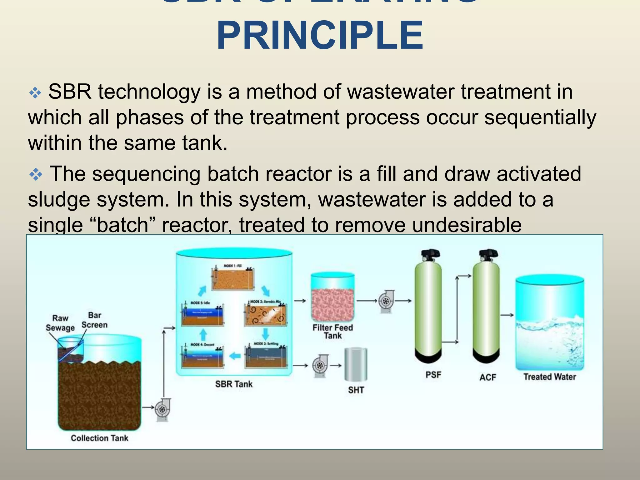
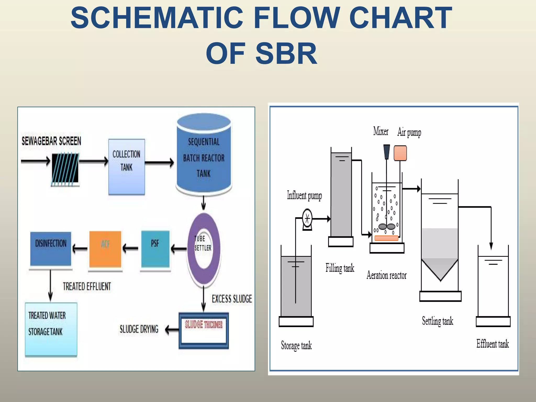
1. The document discusses sequencing batch reactors (SBRs), which are a type of activated sludge wastewater treatment process. SBRs perform treatment steps sequentially in a single batch reactor tank rather than separate tanks.
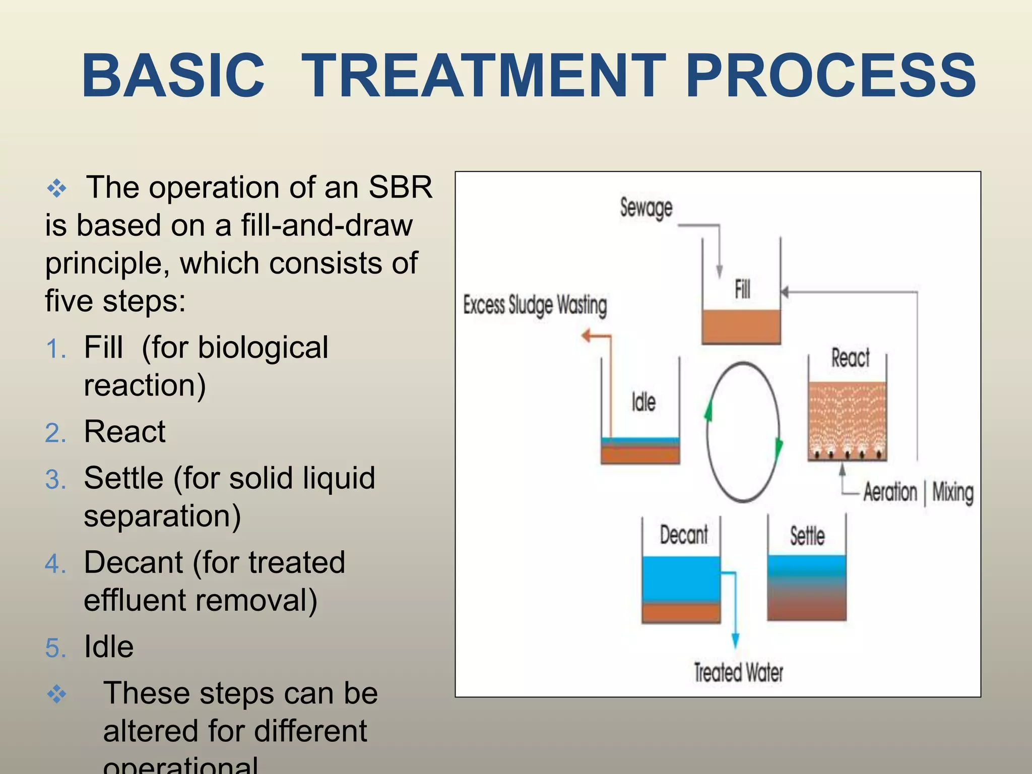
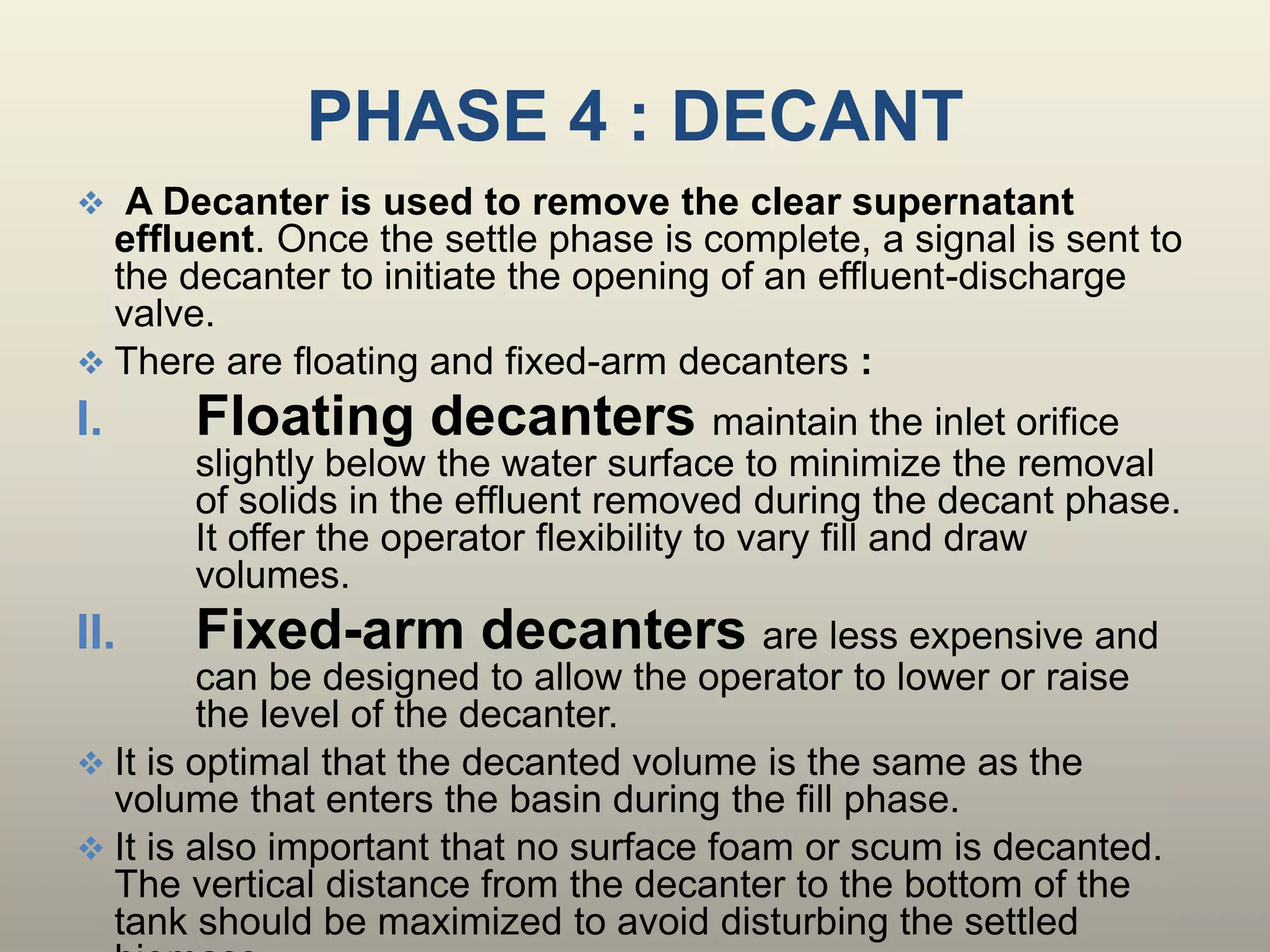
2. The basic SBR treatment process consists of 5 sequential steps - fill, react, settle, decant, and idle. During each step, mixing and aeration conditions in the tank are carefully controlled.
3. SBRs offer advantages over conventional wastewater treatment systems as they can achieve equalization, primary treatment, biological treatment and secondary clarification in one compact system with lower capital and operating costs. However, they require more sophisticated controls and maintenance.