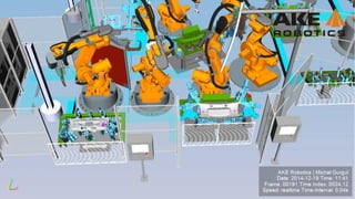
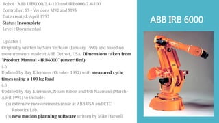
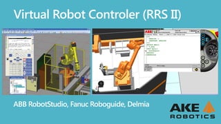
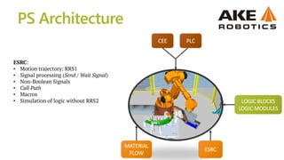
![RRS_INITIALIZE
RRS_SET_INITIAL-POSITION
RRS_GET_NEXT_STEP
RRS_SET_OVERRIDE_ACC
[X, Y, Z, Rx, Ry, Rz]
SET_NEXT_TARGET
RCS
RRS](https://image.slidesharecdn.com/virtualcomisionningprocesssimulate-mgurgul-150208044340-conversion-gate02/85/Robotics-Virtual-Commissioning-in-Process-Simulate-8-320.jpg)
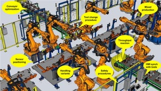


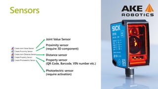
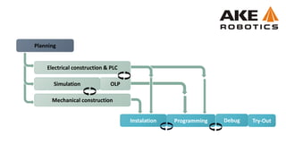
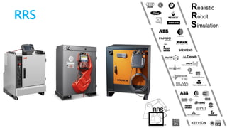
![welding
tip_dress
handling
handling_end
welding_end
tip_dress_end
Transitions conditions
handling
Signal
value
t[s]
0
1
Connections in Gantt Chart
don’t determine operations
executing order!
CEE
parts_counter>=20
part on FX](https://image.slidesharecdn.com/virtualcomisionningprocesssimulate-mgurgul-150208044340-conversion-gate02/85/Robotics-Virtual-Commissioning-in-Process-Simulate-21-320.jpg)


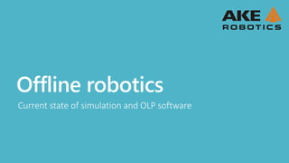
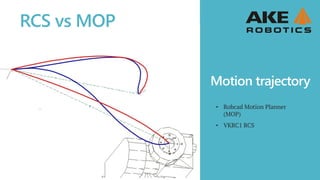
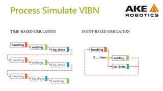
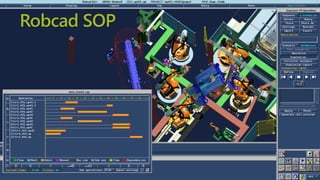
![• Simulation is very complex and require 100% verified documentation.
[mechanical CAD data, ePlan, cycle time diagrams].
• Expensive H/W equipment to run the simulation tools, along with the cost
of licenses.
• Process simulation software is not ready for full VC, many open issues and
bugs on the software.
Cons](https://image.slidesharecdn.com/virtualcomisionningprocesssimulate-mgurgul-150208044340-conversion-gate02/85/Robotics-Virtual-Commissioning-in-Process-Simulate-27-320.jpg)

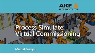
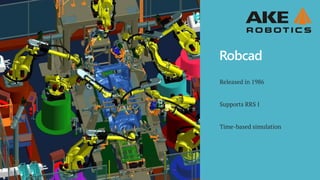
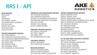
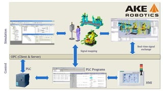
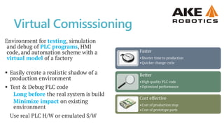
![Hemming
nhOffsRoller := [[0.015,10.2,-17.5],OrientZYX(0.00,0.00,9.9907)];
GHO := [[0,0,0],[0,0,0],[0,0,0]];
NHsetHO 10, 0, 0, 0, 0, 0, -10, 20;
MoveJ NHTarget(f57_area4,HO{10}),v2500,z10,t_r2_cl,WObj:=wobj_15FX16;
! Spot lsp195621_f57;
VP_SpotL lsp195621_f57,Id_03, vmax, t_Gun1_varioWobj:=wobj_22fx16_f57;
!Move VarioPiker Backward
VP_GunOpen 1000;](https://image.slidesharecdn.com/virtualcomisionningprocesssimulate-mgurgul-150208044340-conversion-gate02/85/Robotics-Virtual-Commissioning-in-Process-Simulate-29-320.jpg)


The document discusses the intricacies of virtual commissioning and simulation processes for robotics, focusing on the ABB IRB 6000 robot and associated software tools like Robcad and RRS. It details the iterative updates to the software, motion planning capabilities, and various services available for robotic simulation and programming, emphasizing the benefits of virtual commissioning such as reduced commissioning time and improved product quality. It also outlines the complexity and challenges associated with simulation due to the need for verified documentation and high costs of hardware and software.